HP P2000 G3 Installation Instructions Manual
Msa systems
Hide thumbs
Also See for P2000 G3:
- Cli reference manual (532 pages) ,
- Reference manual (148 pages) ,
- User manual (76 pages)
Advertisement
Quick Links
HP P2000 G3 MSA Systems
Installation Instructions
© Copyright 2009, 2012 Hewlett-Packard Development Company, L.P.
HP Part Number: 590335-009
*590335-009*
Published: January 2012
Edition: 9
About this document
This document is for the person who installs, administers,
and troubleshoots servers and storage systems. HP
assumes that you are qualified in servicing and installing
computer equipment, and are trained in recognizing
hazards in products and hazardous energy levels. For
complete installation and configuration information, see
the user guide for your HP P2000 G3 MSA System. User
documents are provided on the Software
Support/Documentation DVD shipped with the product
and on HP Manuals website:
http://www.hp.com/
support/manuals.
Installing an HP P2000 G3 MSA System includes the
following steps:
Step 1. Install equipment in the rack
Step 2. Install hardware options
Step 3. Connect drive enclosures to the P2000 G3 MSA
array controller enclosure
Step 4. Connect the P2000 G3 MSA System to data
hosts
Step 5. Connect the P2000 G3 MSA System to a remote
management host
Step 6. Connect two P2000 G3 MSA Systems to
replicate volumes
Step 7. Power on components
Step 8. Update firmware
Step 9. Configure the MSA
Step 1. Install equipment in the rack
Site requirements
Ensure that all environmental requirements are met. For
more information about site requirements, see the racking
instructions poster and user guide for the devices.
Rack planning
HP Modular Smart Array (MSA) Systems are supported
for installation in the HP 10000 series of racks. (Other
racks might also be suitable, but have not been tested.)
For information about setting up the rack, including the
appropriate warnings and cautions, see the
documentation that came with your rack. Download
updated rack information at:
http://www.hp.com/
products/racks.
Rack the devices
To install the equipment in the rack, use the racking
instructions poster or other instructions provided with
each device (P2000 G3 MSA array controller
enclosures, supported drive enclosures, servers, and
switches.)
Step 2. Install hardware options
For information about installing controllers, disk drives,
and other options, see the installation instructions
provided with the option. Installation instructions are
also available on the Software Support/Documentation
DVD.
Illustrations in this section describe the different P2000
G3 MSA array controller models.
IMPORTANT:
Do not install different types of
controllers in the same enclosure chassis (for
example, a P2000 G3 Fibre Channel MSA
Controller and a P2000 G3 Combo FC/iSCSI
MSA Controller). This is not supported.
P2000 G3 Fibre Channel MSA
1. Power supplies
2. Fibre Channel host ports
3. CLI port (mini-USB)
4. Reserved for future use
5. Management Ethernet port
6. SAS expansion port
P2000 G3 Combo Fibre Channel/iSCSI MSA
1. Power supplies
2. Fibre Channel host ports
3. iSCSI host ports
4. CLI port (mini-USB)
5. Reserved for future use
6. Management Ethernet port
7. SAS expansion port
Page 1
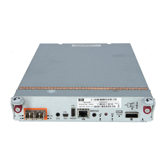
P2000 G3 SAS MSA
1. Power supplies
2. CLI port (mini-USB)
3. Reserved for future use
4. Management Ethernet port
5. SAS expansion port
6. SAS host ports
P2000 G3 10GbE iSCSI MSA
1. Power supplies
2. 10GbE SFP+ iSCSI host ports
3. CLI port (mini-USB)
4. Reserved for future use
5. Management Ethernet port
6. SAS expansion port
P2000 G3 1GbE iSCSI MSA
1. Power supplies
2. iSCSI host ports
3. CLI port (mini-USB)
4. Reserved for future use
5. Management Ethernet port
6. SAS expansion port
Advertisement

Related Manuals for HP P2000 G3


Summary of Contents for HP P2000 G3
- Page 1 For complete installation and configuration information, see Step 2. Install hardware options the user guide for your HP P2000 G3 MSA System. User documents are provided on the Software For information about installing controllers, disk drives, 1.
- Page 2 Step 4. Connect the P2000 G3 MSA System module may result in data throughput at the lower 3Gb/s to data hosts rate. For more information, see the HP P2000 G3 MSA2000 I/O MSA2000 I/O SAS to SAS MSA System Cable Configuration Guide.
-
Page 3: Direct-Connect Configurations
64 host ports, as long as the total Connecting a P2000 G3 SAS MSA dual-controller array adds up to no more than 512 LUNs per P2000 G3 MSA enclosure to one server in a dual-path configuration System. - Page 4 P2000 G3 SAS MSA connected to two servers P2000 G3 10GbE iSCSI MSA connected to one server P2000 G3 iSCSI MSA connected to one server P2000 G3 iSCSI MSA connected to four servers Connecting a P2000 G3 SAS MSA dual-controller array...
- Page 5 Connecting a P2000 G3 Combo FC/iSCSI MSA Connecting a P2000 G3 10GbE iSCSI MSA Connecting a P2000 G3 iSCSI MSA dual-controller the P2000 G3 MSA controller to the switch ports, and dual-controller array enclosure to four switches/four dual-controller array enclosure to two switches/two array enclosure to four switches/four servers in a from switch ports to data hosts.
- Page 6 Information contained herein is subject to change without has a power button, apply power by using the a volume on a primary P2000 G3 MSA System to a notice. The only warranties for HP products and services power switch on the rear of the unit.