Table of Contents
Advertisement
WARNIGN
INSTALLATON
PEAR PANEL
WARNIGN
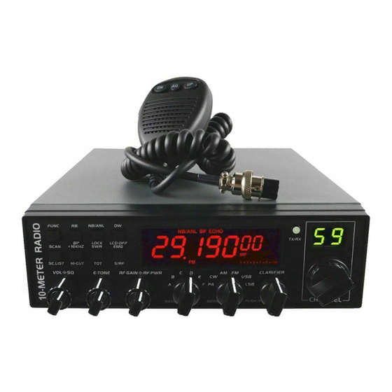
To use the radio, please connect the antenna to the location "B" on the back panel of the
equipment firstly and then set the SWR (Standing Wave Ratio) before transmitting. Failure
to do so may result in destruction of the power amplifier, which is not covered by the
guarantee.
Welcome to Use
Welcome to the world of new CB radios. The new AT-5555 Radio provides you with top
AT-5555 RADIO USER'S MANUAL
TABLE OF CONTENTS
Advertisement
Table of Contents

Related Manuals for AnyTone AT-5555


Summary of Contents for AnyTone AT-5555
-
Page 1: Table Of Contents
SWR (Standing Wave Ratio) before transmitting. Failure to do so may result in destruction of the power amplifier, which is not covered by the guarantee. Welcome to Use Welcome to the world of new CB radios. The new AT-5555 Radio provides you with top... -
Page 2: Reset Function
CB radios. Moreover, with multiple connecting ports in the radio, AT-5555 Radio is ready for future upgrading and functions expanding. To ensure that you use the radio to the fullest, please read this manual carefully before installing and using your AT-5555 Radio. -
Page 3: Where And How To Mount Your Cb Radio
10. SQ, ASQ Function (FM and AM mode only) 11. RF GANI ADJUSTMENT 12. RF PWR ADJUSTMENT 13. SCAN FUNCTION 14. RB FUNCTION 15. NB/ANL FUNCTION 16. DW DUAL-WATCH FUNCTION 17. BEEP VOICE PROMPT 18. +10KHZ Function 19. SWR S/RF DC Voltage display function 20. -
Page 4: Antenna Installation
set. Choose where to place the microphone support and remember that the microphone cord must stretch to the driver without interfering with the controls of the vehicle. 2) ANTENNA INSTALLATION a) Choosing your antenna: For CB radios, the longer the antenna, the better its results. Your dealer will help you with... -
Page 5: Power Connection
A fixed antenna should be installed in a space as clear as possible. If it is fixed to a mast, it will perhaps be necessary to stay it, according to the laws in force (you should seek professional advice). All AT-5555 antennas and accessories are designed to give maximum efficiency to each CB radio within the range. -
Page 6: Basic Operation
the engine block or to the chassis. If this is not the case, you should consult your dealer. WARNING: Lorries generally have two batteries to supply a voltage of 24 volts, in which case it will be necessary to insert a 24/12 volt converter into the electrical circuit. The following connection steps should be carried out with the power cable disconnected from the set. -
Page 7: Adjustment Of Swr(Standing Wave Ratio)
b) Check the antenna connections c) Turn the set on by turning the volume knob clockwise d) Turn the squelch knob to minimum e) Adjust the volume to a comfortable level Go to channel 20@D band by using either the UP or DN key on the microphone or the rotary knob. -
Page 8: How To Use Your Cb Radio
to 1 (an SWR reading between 1 and 1.8 is acceptable). HOW TO USE YOUR CB RADIO <LCD Display> 7 digits: Display frequency and any other information Indicating bars: Indicate RX, RSSI, PA, PWR, SWR The first decimal point: Appears when current channel is edited with SCAN DEL. FUNC Appears after pressing FUNC key AQ Appears when ASQ function is started (only for AM/FM) RB Appears when Roger beep function is started (enabled) -
Page 9: Front Panel
2. Appears when CLARIFIER FUNCTION is COARSE operation or RT operation. 3. Appears when CLARIFIER FUNCTION is transmitting frequency regulated. <FRONT PANEL> 1. OFF/ON/VOLUME Inner Dual Concentric . Turn clockwise to switch on the CB radio and set desired volume level. Under normal operating state, the VOLUME control is used to adjust the output volume obtained either by the transceiver speaker or the external speaker or the external PA speaker, if used. - Page 10 This switch is for adjusting sensitivity during reception. For long distance communications RF GAIN should be set to maximum. RF GAIN can be reduced to avoid distortion, when your correspondent is close by and when he does not have RF POWER. The normal setting of this function is on maximum (fully clockwise).
- Page 11 13. RECEIVER/TRANSMIT INDICATOR When it is receiving, the LED will be green. The LED will be red when it is transmitting. 14. LCD DISPLAY Display frequency, all kinds of information and icons. 15. FUNC This is functional key. Press and hold this key for 2seconds to enter into Functions Menu Setup (refer to Functions Menu for more details).
- Page 12 FUNC NB/ANL Press FUNC NB/ANL to realize the Keyboard Lock function. When this function is enabled, all keys are invalid except PTT, BAND SWITCH, and MODE SWITCH. When pressing any key except PTT, BAND SWITCH, MODE SWITCH, the LOCK icon will display on the LCD.
- Page 13 Press the SCAN key to enable the SCAN function. Before enabling the SCAN function, firstly turn the SQ control clockwise till the background noise is cut out. Then press the SCAN key, radio will automatically scan all channels continuously in the scan list and the SC icon will appear on the LCD.
- Page 14 bars indicate SWR value other than PA or PWR value. One bar displaying on the LCD indicates that SWR value is 1.0. Each additional bar indicates every 0.1 added value. Repeat this operation to switch ON/OFF the function. FUNC+ SWR When pressing this key, TOT ON or TOT OFF would display on the LCD for 2 seconds.
-
Page 15: Press-To-Talk Microphone
24. EXT SP or PA SP EXT SP Accept 4 to 8 ohm, 4 watt external speaker to be connected. When external speaker is connected to this jack, the built-in speaker is automatically disconnected. PA SP It is used to connect a PA speaker. Before operating PA, you must firstly connect a PA speaker to this jack. -
Page 16: Function Menu Setup
26. PTT Transmitting key, Press to speak and release to receive a message. 27.UP/DN These key allow increasing or decreasing a channel number. 28. AQ When the radio is receiving a call, press this key to enable ASQ (Automatic Squelch Control) function. - Page 17 desired amendments. To enter Function Menu: under ON state, press and hold FUNC key for more than 2seconds, and then release the FUNC key to enter into the Function Menu Setup. Under this condition, press FUNC key to select different functions menu, CHANNEL SELECTOR Switches to change the data of Function Menu.
- Page 18 COA: When this option is selected, press PUSH and turn CLARIFIER knob to realize COARSE function. When pressing this key, “2” icon will appear on far left of the LCD. Under this condition, rotate the CLARIFIER knob to change frequency of both transmitting and receiving.
- Page 19 This menu is to set Scan Type. Options are as follows: SQ: When SQ is selected, scan would stop when a valid signal is detected. The radio would resume scanning after signal disappears for 5s. TI: When TI is selected, scan would stop when a valid signal is detected. The radio would resume scanning 5 seconds later, whether signal disappears or not.
- Page 20 surpasses the voltage setup in advance, the radio would display “DC LO” or “DC HI” to remind you that the voltage is not in normal state. Meanwhile, the radio will prohibit transmitting and emit beep prompt. OFF: When OFF is selected, the Power Supplying Voltage is disabled. Default: ON (DC 10.5V-16V) TLD (Content displayed on the LCD when transmitting) This menu is to set the content displayed on the LCD when transmitting.
-
Page 21: Operating Procedure To Receive
50ms. Default: 500ms CFR (CW Side Tone Frequency) This menu is to select CW Side Tone Frequency from 300HZ 3KHZ, the shift step is 10HZ. Default: 1050HZ TON (Transmitting Single-Tone Frequency) This menu is to select Transmitting Single-Tone Frequency from 300HZ-3KHZ. The shift step is 10HZ. -
Page 22: Operating Procedure To Transmit
OPERATING PROCEDURE TO TRANSMIT 1. Select the desired channel of transmission 2. Press the Push-To-Talk switch on the microphone and speak in a normal voice. SPECIFICATIONS General Frequency Range 25.615MHZ—30.105MHZ (Programmable) Frequency Band A/B/C/D/E/F Channel 60 channels (programmable) in each band Frequency Control Phase-Locked-Loop Synthesizer Frequency Step... - Page 23 FM: 1.0 V for 20 dB (S+N)/N at greater than 1/2 watt of audio output Selectivity AM/FM:6dB@3KHz,50dB @9KHz SSB: 6 dB@2.1KHz,60dB @3.3KHz Image Rejection More than 65dB IF Frequency AM/FM: 10.695 MHz 1st IF, 455 KHz 2nd IF SSB: 10.695 MHz Adjacent-Channel 60dB AM/FM &70 dB SSB Rejection...
Need help?
Do you have a question about the AT-5555 and is the answer not in the manual?
Questions and answers
I own a AT-55555N 10-meter radio...S/NO.0760A170400285. Is it possible to update that radio with firmware for the AT-55555N II.