
Related Manuals for AnyTone AT- 778UV


Summary of Contents for AnyTone AT- 778UV
- Page 1 User Manual DUAL BAN D MOBILE RADIO (Scanning Receiver) Model: AT- 778UV Qixiang Electron Science & Technology Co., Ltd...
- Page 2 Qixiang Electon Science & Technoloyg Co.,Ltd. www.anytone.net NOTE: This equipment has been tested and found to comply with the limits for a Class B digital device, pursuant to part 15 of the FCC Rules. These limits are designed to provide reasonable protection against harmful interference in a residential installation.
- Page 3 AT-778UV Instruction Manual...
-
Page 4: Table Of Contents
CONTENTS 1.FUNCTIONS & FEATURES ................1 2.ACCESSORIES ..................... 2 3.INITIAL INSTALLATION ................3 4.GETTING ACQUAINTED ................8 5.DISPLAY MODE ................... 11 6.BASIC OPERATIONS .................. 12 7.FUNCTION MENU ..................16 8.CHANNEL MENU ..................21 9.KEYPAD MENU SETUP ................25 10.DTMF SETTTING ..................26 11.PROGRAMMING SOFTWARE .............. -
Page 5: Functions & Features
1. FUNCTIONS & FEATURES AT-778UV Mobile Radio has nice housing, stoutness & stability, advanced and reliable functions, perfect & valuable. This amateur mobile radio especially designs for drivers and it pursues philosophy of innovation and practicality. More functions as follows: Adopt superior quality material, better technology and high quality radiator to ensure stable and durable operation;... -
Page 6: Accessories
2. ACCESSORIES 2.1 Standard Accessories FUNC DC Power Cable with Fuse Holder 2.2 Optional Accessories PC cable External Speaker (PC51) Regulated Power Supply Programming Software AT-778UV UHF/VHF Two Way Radio... -
Page 7: Initial Installation
3. INITIAL INSTALLATION 3.1 Mobile Installation To install the transceiver, select a safe, convenient location inside your vehicle that minimizes danger to your passengers and yourself while the vehicle is in motion. Consider installing the unit at an appropriate position so that knees or legs will not strike it during sudden braking of your vehicle. - Page 8 1.Route the DC power cable supplied with the transceiver directly to the vehicle's battery terminals using the shortest path from the transceiver. We recommend you do not use the cigarette lighter socket as some cigarette lighter sockets introduce an unacceptable voltage drop. The entire length of the cable must be dressed so it is isolated from heat, moisture, and the engine secondary (high voltage) ignition system/ cables.
- Page 9 Regulated power supply Black Regulated power supply DC power cable with fuse holder (QPL-01) 2.Connect the transceiver's DC power connector to the connector on the DC power cable. » Before connecting the DC power to the transceiver, be sure to switch the transceiver and the DC power supply OFF.
- Page 10 3.3 Antenna Connection will depend largely on the type of antenna and its correct installation. The transceiver can give excellent results if the antenna system and its installation are given careful attention. the antenna system and can cause interference to nearby broadcast television receivers, radio receivers, and other electronic equipment.
- Page 11 Error SP-01 Ground 3.4.2 Microphone For voice communications, connect a microphone equipped with an 8-pin modular plug into the modular socket on the front of the main unit. Press irmly on the plug until the locking tab clicks. FUNC Microphone connector AT-778UV UHF/VHF Two Way Radio...
-
Page 12: Getting Acquainted
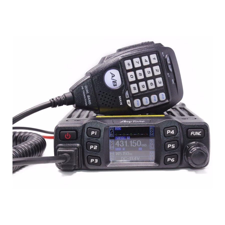
4. GETTING ACQUAINTED 4.1 Front panel FUNC Functions Power On/Off/Mute Function key/ function group key Microphone Jack Channel switch/Push button/Key lock LCD display Display channel/frequency/function setting 4.2 Rear panel EXT SP AT-778UV UHF/VHF Two Way Radio... - Page 13 Functions Antenna connector Connect a 50 ohm antenna Ex-Speaker Jack Connect optional SP-01 external speaker Power cable Connect a standard DC power cable 4.3 Display 11 12 18 19 20 21 22 Functions Displays the main channel TX or RX status Displays when Automatic power off function is on Displays main channel number in channel mode Displays when set band width for main channel...
- Page 14 4.4 Microphone Functions Increase frequency, channel number or setting value DOWN Decrease frequency, channel number or setting value Press the PTT (Push-TO-Talk) key to transmit Number Key Input VFO frequency or DTMF dial out etc. A/B band Choose left band or right band as Main band Band indicator The indicator light on for Main band TX/RX indicator...
-
Page 15: Display Mode
5. DISPLAY MODE LCD display mode. A. Frequency+Channel mode: When set display as "FRQ", it enters into Frequency+Channel mode, new setting of channel operation and shortcut operation can be temporarily used by user. Once the radio is turned off or switched to anothe channel, the temporary setting will (pic1)... -
Page 16: Basic Operations
6. BASIC OPERATIONS 6.1 Switching the Power On/Off 1. Power On: in power off state press WELCOME displays current frequency or channel. 2. Power Off: in power on state, press CLOSING then the LCD display disappears. 6.2 Adjusting the Volume 1. - Page 17 6.5 Receiving When the channel you are operating being called, the screen shows red RX and field strength in this way you can hear the calling. » current channel receive a matching carrier but unmatching signaling. Refer to CTCSS/ DCS CODE or Optional Signaling setup in Page 14). 6.6 Transmitting Hold [PTT] and speak into microphone.
- Page 18 6.10 Channel Delete 1. In channel mode, turn the channel knob or microphone [UP]/[DOWN] key to choose an unwanted channel. M function, press this key together with [FUNC] key for 2 seconds, current channel is deleted and automatical jump to next channel. 6.11 CTCSS/DCS Encode and Decode Setup 1.
- Page 19 6.14 Frequency/Channel Scan Frequency Scan In frequency (VFO) mode, this function is designed to monitor signal of all frequency points under each step size. 1. In VFO mode, short press [FUNC] key to switch function group, choose the [PX] key 2.
-
Page 20: Function Menu
6.18 Transmit DTMF/5 Tone Signaling If the current channel is with DTMF/5TONE signaling, hold PTT and [UP] key will transmit selected Pre-programmed signaling. 6.19 Transmit Tone burst frequency Hold PTT and [DOWN] key will transmit selected Pre-programmed tone burst frequency. 6.20 Transmit DTMF by Microphone Keypad Hold PTT, then input DTMF signaling by the microphone keypad. - Page 21 7.3 Display mode setup 2. Press [PUSH] button, the menu value in LCD turns to green color. 3. Turn channel knob to choose wanted setting. FRQ: Frequency+Channel mode(Amateur transceiver mode) CH: Channel mode(professional transceiver mode) NM: Channel+name mode+ Channel mode(Amateur transceiver mode), If channel not named, it display Fequency + Channel mode, otherwise displays the channel name( Amateur transceiver mode).
- Page 22 TO: It pause for preset pause time when scanning a matching signal, then resume scan. CO: It pauses once scanning a matching signal, and resume scan when signal disappears. SE: It stops once scanning a matching signal. 7.8 Scan Pause Time Setup 1.
- Page 23 7.12 TOT(Time Out Timer) The time-out timer limits continuous transmitting time. When transmit time last over programmed value, the transmitting will stop and emit a prompt. 1. Enter FUNCTION MENU list, choose No.12 function 2. Press [PUSH] button, the menu value in LCD turns to green color 3.
- Page 24 7.16 Microphone Speaker 1. Enter FUNCTION MENU list, choose No.16 function 2. Press [PUSH] button, the menu value in LCD turns to green color 3. Turn channel knob to choose wanted setting. M&H: Turn on Main speaker and microphone speaker. MAIN: Turn on Main speaker.
-
Page 25: Channel Menu
8. CHANNEL MENU 1. Hold [FUNC] key to enter SELECT MENU interface. 2. Short press [P4] key, [P6] key or turn channel knob to choose menu list. Short press [P5] key can fast turn page. 3. Press [PUSH] button to enter CHAN MENU list 4. - Page 26 3. Turn channel knob to choose wanted setting HI: Choose high power level. MI: Choose middle power level. LO: Choose low power level. 8.4 5TENC (5TONE ENCODE SELECT) 1. Enter CHAN MENU, choose No.4 function; 2. Press [PUSH] button, the menu value in LCD turns to green color. 3.
- Page 27 C/T: You can hear the calling when receives any matching carrier or CTCSS/DCS or optional signaling. » This settting is valid only when CTCSS/DCS signaling added. 8.7 Band-width Selection Select suitable bandwidth in accordance with different local conditions 1. Enter CHAN MENU list, choose No.7 function 2.
- Page 28 -: Minus offset, means transmitting frequency lower than receiving frequency. +: Plus offset, means transmitting frequency higher than receiving frequency. OFF: OFFSET is turn off. UHF: 0 - 90 Mhz frequency avaiable. » when RTDF function is on. 8.11 Editing Channel Name After edit a name for a channel, if the display mode is channel name, the radio will display the name edited in this menu.
-
Page 29: Keypad Menu Setup
9. KEYPAD MENU SETUP 9.1 Main unit keypad menu setup 1. Hold [FUNC] key to enter SELECT MENU interface. 2. Short press [P4] key, [P6] key or turn channel knob to choose menu list. Short press [P5] can fast turn page. 3. -
Page 30: Dtmf Settting
10. DTMF SETTTING 10.1 DTMF Encode group setting 1. Enter DTMF menu. choose No.1 function 2. Press [PUSH] button, the menu value in LCD turns to green color. 3. Turn channel knob to choose wanted setting. 1-16 total 16 groups DTMF encode for selection. 4. -
Page 31: Programming Software
11. PROGRAMMING SOFTWARE INSTALLING AND STARTINGSOFTWARE I Install USB Cable Driver Programme 1. Click start menu in computer, under “ALL PROGRAMS” menu, choose and click “USB To Com port” in AT-778UV program, install “USB To Com port” driver by indication. 2. -
Page 32: Maintenance
12. MAINTENANCE 12.1 Default Setting after Resetting Frequency band VFO frequency 145.150MHz Memory channel Offset direction Offset frequency 600KHz 5MHz Channel step 10KHz 10KHz CTCSS encode and decode -- CTCSS tone frequency 88.5Hz 88.5Hz DCS encode and decode DCS Code 000N 000N Output power... -
Page 33: Specifications
13. SPECIFICATIONS GENERAL Frequency Range Number of Channels 200 channels Channel Spacing 25K (Wide Band) 20K(Middle Band) 12.5K (Narrow band) 2.5KHz, 5KHz, 6.25KHz, 10KHz, 12.5KHz, 20KHz, 25KHz, Phase-locked Step Operating Voltage Squelch Carrier/CTCSS/DCS Frequency Stability Operating Temperature -20 ~+60 Dimensions(mm) Weight about 0.64Kg »... -
Page 34: Attached Chart
14. ATTACHED CHART 52 groups CTCSS Tone Frequency(Hz) No. Freq.(Hz) No. Freq.(Hz) No. Freq. (Hz) No. Freq. (Hz) No. Freq. (Hz) 62.5 94.8 218.1 67.0 97.4 179.9 225.7 100.0 146.2 229.1 71.9 151.4 196.2 74.4 107.2 156.7 189.9 241.8 77.0 110.9 159.8 192.8... -
Page 35: Groups Dcs Code
1024 groups DCS Code Code Code Code Code Code Code Code Code (Octal) (Octal) (Octal) (Octal) (Octal) (Octal) (Octal) (Octal) 100. 101. 102. 103. 104. 105. 106. 107. 108. 109. 110. 111. 112. 113. 114. 115. 116. 117. 118. 119. 120. - Page 36 313. 314. 315. 316. 317. 318. 319. 320. 321. 322. 323. 324. 325. 326. 327. 328. 329. 330. 331. 332. 333. 334. 335. 336. 337. 338. 339. 340. 341. 342. 343. 344. 345. 346. 347. 348. 349. 350. 351. 352. 353.
Need help?
Do you have a question about the AT- 778UV and is the answer not in the manual?
Questions and answers
What power supply can I use.
A compatible power supply for the AnyTone AT-778UV should provide an output voltage of 13.8V DC, adjustable between 9.0V and 15.0V, with a maximum output current of 30A and a continuous output current of 20A. The power supply should also have short-circuit protection and automatic current limiting within 30A.
This answer is automatically generated
DO YOU HAVE THE INSTRUCTION MANUAL FOR ANYTONE AT778UV IN SPANISH/
Yes, the instruction manual for the AnyTone AT-778UV is available in both Spanish and English.
This answer is automatically generated
How to turn of password
To turn off the password on the AnyTone AT-778UV:
1. Access the password setting (labeled "PW").
2. When the password is on, the indicator will be green.
3. Press the corresponding button to confirm and turn it off.
4. The indicator will turn white, meaning the password is now off.
This answer is automatically generated
Jak zvýšit modulaci při vysílání. Modulace je slabá pro volané stanice