Table of Contents
Advertisement
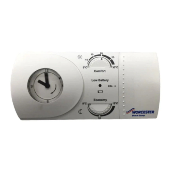
INSTALLATION AND OPERATING INSTRUCTIONS
RADIO FREQUENCY CONTROLLED SINGLE CHANNEL MECHANICAL
TIMER AND ROOM THERMOSTAT WITH RECEIVER
MT10RF / MECHANICAL
RF THERMOSTAT
7 716 192 037 FOR GREENSTAR i, Si, CDi AND HIGHFLOW CDi COMBINATION BOILERS
Comfort
Low Battery
Economy
UK/IE
override
8716115752-00.1 Wo
Advertisement
Table of Contents

Related Manuals for Worcester MT10RF


Summary of Contents for Worcester MT10RF
- Page 1 INSTALLATION AND OPERATING INSTRUCTIONS RADIO FREQUENCY CONTROLLED SINGLE CHANNEL MECHANICAL TIMER AND ROOM THERMOSTAT WITH RECEIVER MT10RF / MECHANICAL RF THERMOSTAT 7 716 192 037 FOR GREENSTAR i, Si, CDi AND HIGHFLOW CDi COMBINATION BOILERS Comfort Low Battery Economy override 8716115752-00.1 Wo...
-
Page 2: Table Of Contents
TABLE OF CONTENTS TABLE OF CONTENTS SYMBOLS AND SAFETY PRECAUTIONS ....3 EXPLANATION OF SYMBOLS ......3 WARNING SYMBOLS . -
Page 3: Symbols And Safety Precautions
SYMBOLS AND SAFETY PRECAUTIONS SYMBOLS AND SAFETY PRECAUTIONS EXPLANATION OF SYMBOLS WARNING SYMBOLS ADDITIONAL SYMBOLS Safety instructions in this document Symbol Meaning are framed and identified by a a step in an action sequence warning triangle which is printed on a grey background. -
Page 4: Manual Information
MANUAL INFORMATION MANUAL INFORMATION GENERAL MECHANICAL TIMER SYMBOLS Please read these instructions before starting. Constant Comfort temperature HESE INSTRUCTIONS ARE APPLICABLE TO THE ORCESTER PRODUCT MODELS STATED ON THE FRONT Constant Economy temperature COVER OF THIS MANUAL ONLY AND MUST NOT BE USED Automatically switches between Com- WITH ANY OTHER MAKE OR MODEL OF APPLIANCE fort and Economy according to the... -
Page 5: Product Information
PRODUCT INFORMATION PRODUCT INFORMATION STANDARD PACKAGE SPECIFICATIONS - Receiver for the Greenstar i, Si, CDi and TRANSMITTER: Highflow CDi combination boilers. Single channel, radio frequency central • - Transmitter heating timer. C - Screws (x2) Mechanical timer with built-in RF transmitter. •... -
Page 6: Technical Data
PRODUCT INFORMATION TECHNICAL DATA Description Units Transmitter Receiver Dimensions H158 x W75 x D36.5 Operating voltage 2 x AA/LR6 Batteries 24V d.c. Ambient Operating Temperature °C -5 to +45 -5 to +45 Class of protection — Degree of protection Accuracy sec/day ±2.5 @ 25°C —... -
Page 7: Installation & Commissioning
INSTALLATION & COMMISSIONING INSTALLATION & COMMISSIONING 4. Align connector pins [F] into receptors [G] in DANGER: the circuit board and push fully home. B 24V & 230V: Do not touch 5. Feed the ribbon cable [G] into recess [H]. electrical components or circuits. -
Page 8: Pre-Commissioned Transmitter & Receiver Location
INSTALLATION & COMMISSIONING PRE-COMMISSIONED TRANSMITTER & RECEIVER LOCATION The MT10RF Mechanical Thermostat and FUNCTIONAL CHECK Receiver are pre commissioned (paired) at the B Move the manual switch on the Transmitter to factory. the constant comfort position. B Rotate the Comfort temperature dial to 30 °C. -
Page 9: Transmitter Location
INSTALLATION & COMMISSIONING TRANSMITTER LOCATION B Position the Transmitter [A] as close to the main living area as possible on an inside wall. Mount approximately 1.5m (5‘) above the floor within the maximum range of the boiler‘s Receiver. Keep the Transmitter away from: light and heat sources •... -
Page 10: Transmitter Radio Link Set Up
INSTALLATION & COMMISSIONING TRANSMITTER RADIO LINK SET UP ESTABLISH A RADIO LINK The procedure will only have to be B Press and hold button [C] down on the followed if problems have been Receiver for approximately five seconds to experienced with the enter the set up mode with the LED [D] on pre commissioned procedure or if: continuously. -
Page 11: Transmitter Clearance & Fixing
INSTALLATION & COMMISSIONING TRANSMITTER CLEARANCE & B Drill holes, where marked, 30mm deep using a 6mm diameter drill bit. FIXING B Push one wall plug [D] into each hole. NOTICE: B All relevant safety precautions must be undertaken. Protective clothing, footwear, gloves and safety goggles must be worn as appropriate. -
Page 12: User Instructions
USER INSTRUCTIONS USER INSTRUCTIONS TRANSMITTER CONTROLS SETTING HEATING TIMES: 3. Using the 1 to 24 hour marks on the outer ring INFORMATION: [G] move the tappets [H - each tappet represents 15 minutes]: Slide open panel [A] to reveal details of setting Comfort and Economy [B]. -
Page 13: Receiver Functions
USER INSTRUCTIONS RECEIVER FUNCTIONS SELECTING PROGRAMS 5. Move the selector switch [L] to set: 5.2.1 NORMAL OPERATION Automatic, Comfort or Economy. B LED [A] is continuously on when there is a – Automatic (switches between and uses demand for heating and continuously off when both Comfort and Economy temperature there is no demand for heating. -
Page 14: Low Battery State
USER INSTRUCTIONS BATTERY REPLACEMENT 5.2.4 EMERGENCY MODE B If a signal is not received for 60 minutes LED The MT10RF Transmitter includes a battery [A] continues to flash rapidly and the central status indicator [A]. heating is switched off. B Press button [B] and release for manual NOTICE: override and to switch the central heating on. -
Page 15: To Replace The Batteries
USER INSTRUCTIONS TO REPLACE THE BATTERIES: B Align outer edge and internal lugs of the transmitter to the base plate [B] and push fit B Locate a flat bladed screwdriver into the slots to secure. in the transmitter base plate [B]. B Twist to lift the transmitter [A] away from the 8716115752-19.1 Wo base plate [B]. -
Page 16: Servicing & Spares
SERVICING & SPARES SERVICING & SPARES TRANSMITTER/RECEIVER SERVICING: MAINTENANCE & SPARES B These units cannot be serviced. B Should the existing unit fail to function TRANSMITTER MAINTENANCE: correctly, check: – the receiver times and program settings are correct – the RF signal link is set up. Comfort –... - Page 17 NOTES 8 716 115 752 (2009/07)
- Page 18 NOTES 8 716 115 752 (2009/07)
- Page 19 NOTES 8 716 115 752 (2009/07)
- Page 20 01905 752556 TRAINING: 01905 752526 SALES: 01905 752640 WEBSITE: www.worcester-bosch.co.uk Dedicated to heating comfort Worcester, Bosch Group Cotswold Way, Warndon, Worcester WR4 9SW Tel. 01905 754624 Fax. 01905 754619 Worcester, Bosch Group is a brand name of Bosch Thermotechnology Ltd. www.worcester-bosch.co.uk...
Need help?
Do you have a question about the MT10RF and is the answer not in the manual?
Questions and answers