
Related Manuals for Kodicom KSR-916


Summary of Contents for Kodicom KSR-916
- Page 1 Please read this manual thoroughly before use, and keep it handy for future reference. USER GUIDE DIGITAL RECORDING SYSTEM KSR-916...
- Page 2 916 Manual 916 Manual This manual is published by KODICOM Co, Ltd and contains information on KSR-916 which will enable you to use this product properly. If you require additional copies of this manual, please print the manual contained in the CD provided with your purchase.
- Page 3 This KSR-916 manual provides necessary information for the correct use of this product and also contains some useful tips. Please read this manual thoroughly before using your KSR-916 in order to prevent possible breakdown due to any mishandling. KODICOM...
- Page 4 KSR-916. • KODICOM can not be held responsible if the DVR is damaged due to non- compatible devices being used with this product. If you have any doubts please check.
- Page 5 Internet. It is also prohibited to post, distribute, or translate this manual without KODICOM’S permission. KODICOM is not held responsible if the DVR is damaged due to the system being handled inappropriately by a user who is not aware of how to operate this product, or by a user who did not refer to this manual before attempting to operate the product.
-
Page 6: P O
Caution Please be aware of the following precautions before installing the DVR. • Avoid positioning the KSR-916 in any place where the unit may come into contact with moisture, dust, or soot. • Avoid placing in direct sunlight or near heating appliances. - Page 7 Do not touch the plug with wet hands • This can cause fire or electric shock. and avoid using the plug if the holes on the outlet are too loose. • This may cause fire or electric shock. KODICOM KODICOM...
- Page 8 Do not use the same outlet with a damaged, or cut. hair dryer, iron, refrigerator, or any heating • This may cause fire, electric shock, or injuries. appliances. • This may cause fire, heating, an electric shock. KODICOM KODICOM...
- Page 9 • This may cause an explosion. assistance for HDD replacement from your dealer. • KODICOM is not responsible for deleted data caused by user’s mishandling. CALIFORINIA USA ONLY This Perchlorate warning applies only to primary CR (Manganese Dioxide) Lithium coin cells in the product sold or distributed ONLY in California USA.
- Page 10 Install the system in a place with sufficient air ventilation. • The system may not operate properly. • Keep at least 15cm distance between the back of the system and a wall, and at least 5cm distance between the side of the system and a wall. KODICOM KODICOM...
- Page 11 Regulator) for stable power supply. service Center. It is recommended to coil the core-ferrite around the connector of the system to avoid • KODICOM is not held responsible for system breakdown caused by user’s mishandling. electromagnetic interference. KODICOM KODICOM...
- Page 12 (The user manual will be included either inside the product software CD or a quick Manual including important contents.) (Manual/Software) Remote Controller Manual (Site/Center) SATA Cable Power Cable Audio Cable (Extra) Mouse Bracket Rack Screws Battery RS-485 Connecter KODICOM KODICOM...
-
Page 13: Table Of Contents
4.3 Camera menu…………………………………………….……………………………………………………58 4.3.1 Channel Setting…………………………...………………..…………………..…………………………………58 4.3.2 Alarm In Setting………………………………………..…………………………………………………………59 4.3.3 Relay Out Setting………..………………………….………………………..…………………………………60 4.3.3.1 Alarm In/Relay Out Link……….………………………..……………..…………………………………61 4.3.3.2 Motion/Relay Out Link…………….…………..…………………………………………………………61 4.3.3.3 System Error/Relay Out Link…….……………..…………………………………………………………61 4.3.4 Alarm In Camera link……………………………..…………………………………………………………62 4.3.5 Spot Out Camera link………..…..….………….………………………..…………………………………62 KODICOM KODICOM... - Page 14 4.5.5 Storage………………………………..………………..…………………………………………………………88 4.5.5.1 External Storages………………………………..………………………………..…………………...88 4.5.5.2 Hard Management…………………..…………….……………………………..…...………….……….89 4.5.5.3 RAID Management………………..…………….………………………………..…...………….……….91 4.5.6 POS Management…………………..………..…………………………………………………………91 4.5.6.1 Data Format Setting……………………………..…….……………………………..…………………….. 91 4.5.6.2 DATABASE Setting……………………..…………….…………………………..…...………….…………93 4.5.6.3 POS Configuration ………………..…………….………………………………..…...………….…………94 4.6 System Info………………………………………….………..………………..………………………………………95 4.6.1 Log Info……………..…………………………………..………………………………..………………………95 4.6.2 Factory Default………….…….…..………..…………………………………………..…………….………...98 4.6.3 System Shutdown/Restart ……….....…………………………..……………..………………..…98 KODICOM KODICOM...
- Page 15 Chapter 6. Backup 6.1 Video Backup ……………………………………………………………………………………..……………108 6.2 Still Image Backup………………………..………………………………………………………..…………109 6.3 Media Format…………………….……………..………………………………………………..…………110 Appendix 1. KDB Viewer……………………………………………………………………….……………………………………112 1.1 How to run Viewer………………………………..……………….…………..…………………………………112 1.2 Viewer main screen……………………………………………..……………………………………………113 2. WebDVR………………..………………………………………………………………………………………………115 3. Watermark Checker………………………………………….………………………………………………………120 4. CMS Software…………………………………………………………………………………………………………122 5. Specifications…………………………………………………………………………………………………………135 6. FAQ………………………………………………………………………………………………………………137 KODICOM KODICOM...
-
Page 16: Chapter 1. Introducing Your Real Time Dvr
1. Introducing your real 1. Introducing your real time DVR time DVR... -
Page 17: Front Panel
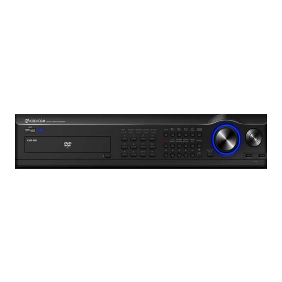
1.1 Front panel 1.1 Front panel The following describes the keys and ports on the front of the system and their functions: 10 11 [System front view(KSR-916)] [Power] • Use this button to shutdown the DVR. • When the button is pressed a password menu will pop-up and password details should be entered click [OK] and the DVR will turn off. - Page 18 [Directional keys] • Use to move through the menu options in Setup or Search mode. • When controlling P/T/Z camera, press the directional keys to move the camera. • When searching recorded image, you can adjust the size of the image using up and down directional key. ☞...
-
Page 19: Network :
[REVERSE PLAYBACK] • USB the [SEARCH] button to playback a selected channel in surveillance mode. [INSTANT BACKUP] • The [INSTANT ACKUP] button once pressed automatically makes a back-up of all channels for the 5 minutes prior to the button being pressed to the USB port. [INSTANT REC] •... -
Page 20: Rear Panel
1.2 Rear panel 1.2 Rear panel The following describes keys and ports on the rear part of the system and their functions. [System rear view(KSR-916)] [Power Connector] 100V ~ 240V, • Power cable input, for system main power supply. [Caution] •... - Page 21 [VGA] • Connect the VGA monitor to the VGA port. • Displays the DVR system on the monitor. [AUDIO IN] • Input speaker into the audio in ports. • Supports recording of up audio channels. Model KSR-916 Audio 16CH Channels...
- Page 22 [AUDIO OUT] • Connect speakers to the Audio Out port in order to output Audio data. ☞ ☞ [Note] The DVR is not equipped with an audio output amplifier. Thus, user are advised to purchase separate amplifiers and speakers or speakers with a built-in amplifier. [USB PORT] •...
- Page 23 ☞ ☞ [Note] Removable Disk The table below lists compatible USB disks. If you want to use other removable disk, it should be compatible with Linux 2.6.0 or over. Other USB disk may not work properly. It is recommended that you confirm through the manufacturer the Linux compatibility of the removal disk you wish to purchase.
-
Page 24: Description Of The Remote Controller
1.3 Description of the Remote controller 1.3 Description of the Remote controller The following describes the remote controller buttons, which have the same functions as the buttons on the front panel of the system: MENU SEARCH NUMBER BACKUP Jog ( + ) Shuttle ( + ) Shuttle ( - ) Jog ( - ) -
Page 25: Chapter 2. Installation
2. Installation 2. Installation... -
Page 26: Checking Install Environment
2.1 Checking install environment 2.1 Checking install environment You should pay attention to the following before you use the product. • Do not use it outdoor. • Do not place water or liquid near the connection part or the product. •... - Page 27 Please keep the following instructions for rack-mounting the DVRs to proceed with the installation. 1. The rack on which the DVR is mounted should not be sealed off. 2. And it also can allow air circulation through the vent. 3. As shown in the Figure 2, we recommend you to heap the product with other DVR s or use rack-mount devices at certain space, or install a vent system to accommodate airflow.
-
Page 28: Rack Installation
※ RacK installation • Loosen the screws on both sides (4 screws on each side) and install theBracket-Rack as shown in the figure, and then fasten the screws on both sides (4 screws on each side). •` Fix the screws not to be loosened by vibrations. ※... -
Page 29: Usb Connection
2.2 USB Connection 2.2 USB Connection USB Cable Connection Port... - Page 30 ※ CONNECTING THE USB • There are two USB ports at the front and one at the back of the product. • You can connect a USB HDD, USB memory or mouse to the USB port. • This product supports hot-plugging, which connects/removes the USB device during the system operation.
-
Page 31: Console Controller
2.3 CONSOLE Controller 2.3 CONSOLE Controller Output for controlling computer. -
Page 32: Connecting Network Communication Lines
2.4 Connecting NETWORK Communication Lines 2.4 Connecting NETWORK Communication Lines 2.4.1 Network and Dedicated Line Connection (Used for connecting to KSR-916 UTP port) Center PC Router Internet Network & Local Intranet Network (Dedicated Modem) (Used for connecting UTP port of the LAN Card) -
Page 33: Pstn (Telephone Line) Connection (Optional)
2.4.2 PSTN (telephone line) Connection (options) (Not available in Europe) MODEM (KSR-916 RS-232 connection) MODEM Center PC... -
Page 34: Alarm-In Port Connection (Input)
2.5 Alarm In Port Connection (Input) 2.5 Alarm In Port Connection (Input) Alarm In Connect one of the two signal lines from the sensor (infrared sensor, magnetic) to G port, and connect the other signal line to the desired Alarm-In number. [Caution] •... -
Page 35: Alarm-Out Port Connection (Output)
2.6 Alarm Out Port Connection (Output) 2.6 Alarm Out Port Connection (Output) Alarm Out Alarm Out (-) (+) Alarm Light, Amplification Siren, External Power ( DC12V ) External Relay, Etc. • During automatic control of an external sensor, the Alarm-Out output port is “interworked” (the value set in “Set Alarm-In/Alarm-Out”... -
Page 36: Chapter 3. Live
3. Live 3. Live... -
Page 37: Screen Layout
3.1 Screen layout 50.0% [Audio recording status] [Camera number] Displays camera number. Shows audio recording enabled. [Camera name] [HDD Capacity/Temperature] Displays camera name. • Display HDD used by percentage and temperature. [Recording status] Displays camera recording mode enabled. [HDD Status] •... -
Page 38: Pop-Up Menu
3.2 POP-UP MENU • You can use this menu by pressing mouse-right button. The benefit of this menu is that user can operate DVR system by simply using mouse. Names Features Search button • It start search mode. • It switches system to setup mode. Menu button •... - Page 39 Names Features • During the live screen click to open the menu 1ch Playback for 1 ch playback mode. •To start sequencing display mode, select single channel screen. Auto button • Press auto display icon to get auto rotation screen. Click to view live image in single channel mode.
-
Page 40: Live Screen Mode
3.3 Live screen mode [To Select 16 way split screen] • Press the 16 way split screen button to view all cameras on one screen. [To Select 9 way split screen] • Press the 9-split screen button to select display of cameras 1-9. Press again to move to next 9 way screen. - Page 41 [Digital Zoom] • To use this function the DVR must be in the live screen mode. • The function can only be used when a single channel is displayed full screen. • Open the popup menu by clicking the right mouse button.
-
Page 42: 1Ch Playback
3.4 1ch Playback During the live screen this feature allows the user to search one channel. First use the mouse to select a screen, single left click to select the screen. The selected screen is highlighted by a green box. Open the popup menu by clicking the right mouse button. -
Page 43: Pan/Tilt Camera
3.5 Pan/Tilt Camera 3.5.1 Switching to Pan/Tilt control mode [Pan/Tilt camera control] • Select the camera channel connected to the P/T/Z camera by using the mouse or camera number keys on the front panel. This will display the channel in full screen mode. •... -
Page 44: Pan/Tilt Camera Control
3.5.2 Pan/Tilt Camera Control In P/T/Z menu, you can switch the P/T/Z camera controls to manual control, as well as changing Zoom, Focus, and Auto Pan settings. [Preset] [P/T/Z model] • There are up to 10 preset positions which can be •... -
Page 45: Supported Pan/Tilt Camera List
SAMSUNG camera a menu list user can select from SAMSUNG Techwin a menu list user can select from KODICOM KRE-303 a menu list user can select from KODICOM KRE-305 a menu list user can select from DONG-YANG DRX-502C... -
Page 46: Alarm Out - Manual Control
3.6 ALARM OUT – Manual Control 3.6.1 Switching to Alarm Out Mode If you wish to use the control devices manually, select the 16-splitscreen mode in Surveillance mode, then press Enter key. You will then be able to select the control devices you wish to use manually. -
Page 47: Chapter 4. System Setup
4. System setup 4. System setup... -
Page 48: User Login
4. System Setup 4.1 User Login To go to the system setup screen, click the [MENU] button on the front of the system. To access the setup menu the user should login using their ID and Password. Once the user has logged in on the DVR they do not need to login again to gain access to setup or search menus. -
Page 49: Motion Detection
4.2.1 Motion detection • Set the motion detection area, sensitivity and alarm for each camera video. Press the [Enter] button after moving the cursor on the camera to be set. [Motion Link Setting] • You can set a motion-link recording for each camera. •... - Page 50 [Motion Camera] • Select the camera that will detect the movement in its motion-detection area by using the mouse wheel or the jog/shuttle on the system. [Link Camera] • Select the cameras that will be linked to the [Motion Camera] by using the mouse or the directional keys.
-
Page 51: Schedule
4.2.2 Schedule • Set the recording type for each camera over a 24 hour period. • Press the [View] button, you can see the recording mode for the selected camera to highlight the type of recording you wish to set. •... - Page 52 [Camera] • Use the mouse wheel or the Jog/Shuttle to select the camera to change its schedule. [Time] • Change the recording time in hourly intervals • Use the mouse to toggle the time or use the jog and shuttle dials on the front of the DVR [REC Option] •...
-
Page 53: Quality/Resolution
4.2.3 Quality/Resolution • The details of the Quality/Resolution menu are as follows: 4.2.3.1 Normal REC Setting • You can set the recorded mode values for normal DVR recording. [Resolution] • Set the screen size for recording. Video Full D1 Half D1 Source NTSC 704x480... -
Page 54: Alarm Rec Setting
[Quality] • Select the recording video quality. Set between the option of LOWEST, LOWER, LOW, NORMAL, HIGH, HIGHER, HIGHEST. [Frame] • Select the number of frames for recording. The number of frames refers to the number of screens recorded per second (fps). [Audio] •... -
Page 55: Network Rec Setting
[Audio] • To recording sound with the selected camera. Select whether to save audio data or not for each camera. [Apply All] • Click the [Apply All] button to apply the current camera setting to all camera. 4.2.3.3 Network REC Setting •... -
Page 56: Alarm Rec Time
[Frame] • Select the number of frames to transmit through network. This will be the number of frames transmitted for every one second. [Apply All] • Click the [Apply All] button to apply the current camera setting to all camera. 4.2.3.4 Alarm REC Time •... -
Page 57: Property
4.2.4 Property • Change the color, brightness and contrast for each camera. [Camera] • Select which channel to set up. [Color/Bright/Contrast] • You can set the color, brightness and contrast of the selected camera. • The adjustment can be made from ‘0’ to ‘255’ using the jog/shuttle or mouse wheel. [Default] •... -
Page 58: Camera Menu
4.3 Camera menu • The details of the camera menu are as follows: 4.3.1 Channel Setting • Set camera status and name, add PTZ protocol to camera. [Camera] • Select the channel to set up the camera. [Camera Available] • Set the use of the selected camera between Enable/Disable and Secure using the mouse scroll wheel or jog/shuttle. -
Page 59: Alarm In Setting
[Camera Name] • The camera name of the selected channel can be set. A virtual keyboard appears if you press the Enter button. • Characters can be input one by moving the cursor. You can input up to 10 characters. If you press [Shift], you can input the uppercase letters and number keys. -
Page 60: Relay Out Setting
4.3.3 Relay Out Setting • Set the activation parameters for the alarm-out devices on the DVR system 4.3.3.1 Alarm In/Relay Out Link • Link Alarm In and Alarm Out devices, and activation time. [Alarm In] • Select the Alarm In number for configuration. [Relay Out] •... -
Page 61: Alarm In/Relay Out Link
4.3.3.2 Motion/Relay Out Link • Link a motion event from a camera channel to activate an Alarm out device. [Motion In] • Select the Camera channel [Relay Out] • Select the Alarm Out device number(s) to link with the camera motion. [Dwell Time] •... -
Page 62: Alarm In Camera Link
4.3.4 Alarm In/Camera link • Link the Alarm In and camera recording. [Alarm In] • Select the Alarm In number for configuration. [Camera] • Choose the cameras you wish to link with the selected Alarm In. • When the Alarm In is trigged, the linked camera(s) will automatically begin recording. 4.3.5 Spot Out/Camera Link •... - Page 63 [Event Dwell Time] • Select the settings for full screen pop-up on the spot monitor output when a motion or sensor event occurs. • Only a channel that is linked with a motion or sensor event will be displayed full screen. •...
-
Page 64: N E T W O R
4.4 Network • The details of the network menu are as follows : 4.4.1 DDNS Setup • DDNS Setup function allows you to use the dynamic IP address connected to the system as if it is a fixed IP Address. [DDNS Site] •... -
Page 65: Network Setup
4.4.2 Network Setup • Input Network connection details for remote access. [Network] • The system supports network connection using Static IP, as well as DHCP, ADSL connections. The other option is to select no network when not networking the DVR. [Note] ☞... - Page 66 [Site IP] • Sets the IP address for the system to be connected to the network, If the connection mode is set to STATIC-IP, the user needs to enter the IP address directly in this location. • If the connection mode is either by DHCP or ADSL, the IP address is provided by the DHCP server or ADSL carrier and will be automatically set.
-
Page 67: Network Test
4.4.3 Network Test • Check the DVR is connected to the network. [Assigned IP] • Assigned IP display the system’s IP address used for remote backup and remote monitoring. [Connection Status] • Connection Status indicates whether the current assigned IP address can be used to connect to the internet. - Page 68 [Time Server] • Press check the box begin to time server. • Check the box [ Time Server]. • Press [OK] button to begin time server of system. • The time server and time client are out of operating simultaneously. [Client] •...
- Page 69 * NTP Server List Area NTP Server Address Worldwide pool.ntp.org Asia Asia.pool.ntp.org Europe Europe.pool.ntp.org North America North-america.pool.ntp.org Oceania Oceania.pool.ntp.org South America South-america.pool.ntp.org Austria at.pool.ntp.org Australia au.pool.ntp.org Belgium be.pool.ntp.org Canada ca.pool.ntp.org Switzerland ch.pool.ntp.org Chile cl.pool.ntp.org Germany de.pool.ntp.org Denmark dk.pool.ntp.org Spain es.pool.ntp.org Finland fi.pool.ntp.org France...
-
Page 70: Emergency Notification
4.4.5 Emergency Notification • When an emergency Alarm in event has occurred, the Emergency Notification either delivers the emergency message and video to the IP address with the CMS or transmits an e-mail. • Press the “CMS” button to set the Emergency Notification by CMS. [Alarm In] •... - Page 71 • Click the “E-mail” button to display the email transmission settings. • Click the [Time Range Setup] button to set up the time range. • To receive emergency notification via e-mail, set the SMTP address, sender’s e-mail address, recipient’s mail address. [Alarm In] •...
- Page 72 [Start On] • To enable the Emergency Notification feature by Alarm In event, selected the “Alarm In” event field. • To enable the Emergency Notification feature using the [Motion] button on the front panel of the system, select the “Motion Button” event field. •...
- Page 73 [Authentication] • Perform security authentication to enable logging into the mail sever (SMTP). This option allows you to encrypt and authenticate IDs and passwords while sending or receiving e-mails. This option is mainly used to be registered into the services of Internet Service Providers (IPSs)/Internet content providers. [TL/SSL encrypted connection] •...
- Page 74 [FTP Server] • Enter the address of the server to which you will send FTP address. [ID] • Enter the user account of the FTP server. [Password ] • Enter the address of the server to which you will send FTP password. [Port] •...
-
Page 75: System Setup
4.5 System Setup • The details of the system setup menu are as follows : 4.5.1 User Management • The details of the User Management menu are as follows:... -
Page 76: Password Setup
4.5.1.1 Password Setup • Change the password for the administrator. [Old Password] • The default password is not designated first time. This must be used when changing the password. [New Password] • A virtual keyboard will appear if the “Enter” button is pressed. -
Page 77: Group Setup
[User Add] •Enter “User ID” and “Password” for the User. Then select the group that the user has permission, there are three options “Group1”, “Group2”, and “Group3”. • If you press “Add”, the entry is registered and displayed in the user list on the right. •... -
Page 78: Site Setup
4.5.2 Site Setup • The details of the Site Setup menu are as follows: 4.5.2.1 Regional Setting • The regional settings menu is for change the DVR time and date to fit the time zone and language to the installation country. Also there is the option for changing the site code which is essential for network connection. - Page 79 [Site Code] • Setup the ID code to the system, for identifying the system when multiple systems are connected through network and to increase network security. • The Site Code comprise 6 digits. When entering Site Code, you can enter a maximum of 6 digits. [Date Type] •...
-
Page 80: Osd Dwell Time
4.5.2.2 OSD Dwell Time • Configure the setup of the on screen display (OSD) and the dwell time for the camera sequencing. • You can turn the display settings in Surveillance mode on or off, such as [OSD All], [Event Monitoring Duration], [Camera Name], [Recording], [Audio], [P/T/Z], [Backup], [Data/Time], [HDD Space], [Dwell Time], [Transparency], [Event Monitoring Trigger], [Live Exit Time] and [Bad Sector Dwell time] displays. -
Page 81: Remote Control Id
4.5.2.3 Remote Control ID • In the situation where multiple DVR are using their own remote controller the Remote controller ID menu allows configure each controller to have it’s own ID. [Remote ID] • In order to control the DVR with a remote controller, set the DVR and the remote control ID the same. •... -
Page 82: Live Audio
4.5.2.5 Live Audio [Audio Live Channel] • Select channel for live audio output. • The units supports only one channel live audio output at a time. [Mute] • Check [Mute] button to disable audio output on audio channel. [Two way Audio Priority] •... -
Page 83: Pip Setting
[Keyboard] • Check “Keyboard” button to enable/disable on keyboard. • In case of setting the baudrate(9600) for ptz camera, you can set the disable mode. If you set the baudrate(9600) for camera menu and baudrate(9600) for ptz camera, you can access them simultaneously. ☞... -
Page 84: Monitor
4.5.2.8 Monitor • Check the image through the HDMI. [Mode] • Select the mode you wish to link with the selected HDMI. [Resolution] • Select the resolution you wish to link with the selected HDMI. ☞ ☞ [Note] HDMI ? •... -
Page 85: Software Upgrade
[Package select] • You can upgrade the system program by using a portable storage device to be recognized by KSR-916. The upgrade package must be in a folder called “update”. Connect the storage device containing an upgrade package to the USB port, then press [Select]. The system will display the number of packages found. -
Page 86: Schedule
4.5.4 Schedule • The details of the Schedule menu are as follows: 4.5.4.1 Backup Schedule • Setup a backup schedule for the recorded video stored on the HDD. The backup will automatically occur during the selected days and times. Create a backup schedule for the selected day (Sun – Sat). [Start Time] &... -
Page 87: System Restart
4.5.4.2 System Restart [System Restart Time] • You can set a time when the system will automatically restart. • Restarting the system on regular basis may help stabilize the system performance. [System Restart Period] • Use the mouse wheel or the jog/shuttle to select [System Restart Period]. You can assign the system to automatically restart [On time only], [Daily], [Every 2 days], [Every 3 days], [Weekly], [Every 2 weeks], [Every 3 weeks], or [Monthly]. -
Page 88: Storage
4.5.5 Storage • The details of the Storage menu are as follows: 4.5.5.1 External Storage • Setup external storage for backup device or extended recording storage device. [External Storage] • Display external storage device type. [Used as] • External Storage can serve as a backup device or the recording device. •... -
Page 89: Hard Management
4.5.5.2 Hard Management • The table shows the system’s built-in HDD’s and their information. You can install up to HDD into the system. • Form the table, you can select the HDD you wish to format, then select [OK] button. •... - Page 90 [Caution] Checking HDD Data Please, pay attention to following information to minimize the change of losing HDD data. • Remember that you should protect HDD from any impact or misuse as this may cause damaged. • The Manufacturer is not responsible for missing data or defects caused by the user’s miss handling.
-
Page 91: Raid Management
4.5.5.3 RAID Management • The RAID Level and Status are shown. • Mirror recording is possible using RAID1 • Check [RAID On] then [Close] to use the internal RAID function. • Press [Yes] to restart the system. • Press [Build] to build the RAID structure on the selected partitions •... -
Page 92: Pos Management
4.5.6 POS Management • The details of the POS menu are as follow. 4.5.6.1 Data Format Setting Enter the POS model, Transaction start, Transaction end, Transaction cancel, Transaction number, • the end of line strings for the desired POS protocol. •... -
Page 93: Database Setting
[Transaction Cancel] • Enter the transaction cancel string. [[Transaction Number] • Enter the transaction number string. [The end of Line] • Use “The end of Line” to transmit POS to RS232 • Use to Lind Feed of ASCII CODE#10. 4.5.6.2 DATABASE Setting •... -
Page 94: Pos Configuration
4.5.6.3 POS Configuration • Connect the POS device to the DVR’s RS-232 port to display and record the POS information. [POS Enable] • Check “POS Enable” button. [POS ID] • Only one camera can connect for each POS ID. • You can use the multi POS using the VSI-PRO. -
Page 95: System Info
4.6 System Info • The details of the System Info menu are as follows : 4.6.1 Log Info • This function shows as series of logged tasks made in operating the DVR system and when the system runs abnormally, it allows finding the error easily so that the problem can be fixed. •... - Page 96 [Time] • If the [Time] button is pressed, the following screen appears. • Select [Time] to change time to view log information recorded on different date/time. • Change [Start Time] and [End Time] using the mouse and mouse wheel or the directional keys and the jog/shuttle, then press [OK] button.
-
Page 97: System Log List
* System Log List Log Type Log Details Description • C(Channel) C REC START/STOP Continuous Recording Start/Stop C(Channel) A REC START/STOP Alarm In Recording Start/End C(Channel) M REC START/STOP Motion Recording Start/End • System SYSTEM START/END System Power ON/OFF SYSTEM NET TIMESET System Time Change SYSTEM SHUTDOWN System Termination... -
Page 98: Factory Default
[Profile Export] • Creates a file with the System Profile that can be saved and used on other KSR-916. • Insert USB storage device into KSR-916 use mouse or Directional keys to select [OK] and start Export. -
Page 99: Chapter 5. Search
5. Search 5. Search... -
Page 100: Accessing Search Mode
5. Search 5. Search 5.1 Accessing Search Mode To go to the Search screen, click the [SEARCH] button shown in the front of the system screen. The login window will then be displayed, enabling the inputting of login ID and password as shown below. •... -
Page 101: Selecting Date And Time
5.3 Selecting date and time • To select the date you wish to view, use the directional keys to select button, then press Enter. This will display a calendar. • Press the arrow buttons ( ) above the calendar to change year/month. •... -
Page 102: Selecting Cameras And Changing Search Bar Line
5.4 Selecting cameras and changing search bar line [Search] • You can select the search data to be selected. [Selecting cameras] • You can select the cameras to be selected. After pressing the Camera1 to Camera16 buttons on the front panel or moving the cursor to the channel to be selected, the cameras can be selected by pressing the [Enter] button. -
Page 103: Audio Output
5.5 Audio Output • To select the date you wish to view, use the directional keys to select button, then press Enter. This will display a calendar. [Audio] • The system can play the video with recorded audio, provided an audio recording device is connected to that channel. -
Page 104: P L A Y B A C
5.6 Playback • If you press [Play] after selecting the channel and date to be searched, the video is played. [Playback buttons ] : Move to the first recorded image for that date. : Reverse Play. : Stop. : Forward Play. : Move to the last recorded image for that date. -
Page 105: E V E N T S E A R C
5.7 Event Search • Event search function can be used to search and display data recorded by motion, or alarm events. •The following Event Search screen will appear if the [Event] button is pressed. [Start Time] and [End Time] • Set the Event search time. - Page 106 5.8 POS • POS Search Function can be used to search and display data recorded during a POS transaction. • The following POS Search function will appear if the [POS] button is pressed. [Start Time] [End Time] • Select the time range of the POS search. •...
-
Page 107: Chapter 6. Backup
6. Backup 6. Backup... -
Page 108: Video Backup
From Search screen display, select [BACKP] button to save a backup copy of the recording using USB HDD, or a portable hard drive such as USB memory stick. The backup files can be saved as SFX, BMP, JPEG, or KDB (KODICOM Data Base) formats. 6.1 Video Backup [Backup Mode] •... -
Page 109: Still Image Backup
☞ ☞ • KDB (Kodicom Data Base) backup enables backup of the video with audio data. However, the other types of backup such as BMP, JPG do not include audio. • When the is archived to USB in KDB format the viewer software will be copied automatically to the USB. -
Page 110: Media Format
6.3 Media Format • On Backup Mode to format external storage equipment (USB, E-SATA) or set partition, select the media (USB or E-SATA) then click the [Format] button [Format] • Click [Format] button after selecting the storage equipment which you want to format on media list. [Establishing partition ] •... -
Page 111: Appendix
Appendix Appendix... -
Page 112: Kdb Viewer
1. KDB Viewer 1.1 How to run Viewer Connect or insert saved KDB type backup data media to computer, Double click [KDBViewer] Folder to open. Double click ‘Viewer.exe’ to run viewer application. -
Page 113: Viewer Main Screen
1.2 Viewer main screen [Scroll button for camera] [Search Line] • This indicates time line for searching data. • Scroll up or down to show camera buttons. • Move the line to the left or right to start searching. [Camera] •... - Page 114 9 10 12 13 14 [Zoom] [Playback] Increases screen size by up to x4. • Be sure to select the camera, time and date to search. • Adjust SKIP and SPEED ratio as you wish. [Digital Zoom] Go to first saved image for selected date Reverse play frame by frame [Zoom In] Click right mouse button to increase the...
- Page 115 [Audio Play Configuration] • When you want to playback audio, select the channel with recorded audio. Audio recording and replay is supported for only one channel. (Audio recording and replay is possible to multi channel. but, a little cut off.) •...
-
Page 116: Webdvr
2. WebDVR Connect WebDVR Connect WebDVR 1. Input DVR IP address to connect on Web Browser (Internet Explorer) as blow picture. [Note] ☞ ☞ • To operate WebDVR without errors on Windows Vista, execute “Internet Explorer” as an administrator. And then you can get the right the access to download ActiveX program. - Page 117 3. After pop-up message, click [Install] to install software. 4. After install is complete, the screen below will be displayed. Insert ID and password to connect to DVR, and then click [Login].
- Page 118 Live Watch Mode Live Watch Mode View Panel : It can be shown live picture from DVR. And each channel screen can be moved through Drag and Drop. Live Watch : Press button to enter the live display. Playback : Press button to enter the search display. Split button : Choose the screen division displayed by 4/6/9/10/13/16 splits.
- Page 119 Search Mode Search Mode View panel: Displays the playback of recorded data. Live Watch : Press button to enter the live display. Playback : Press button to enter the search display. Split button : Choose the screen division displayed by 4/6/9/10/13/16/25/33/36 splits. Search date : Input the search date and time.
-
Page 120: Watermark Checker
3. Watermark Checker Double click ‘WMChecker.exe’ to run Watermark program Press ‘File Open’ button to select backup still image data (BMP,JPEG) Select image to check forgery. - Page 121 4 If select correctly, it will be shown as below picture. Press [Water mark Check] button to check forgery of selected file as below pictures B. Original Image A. Modified Image...
-
Page 122: Cms Software
4. CMS Software Insert CMS CD, and “install.exe” to run the installation program. If shot down the above program, you can possible to “install.exe” to run the installation program. Click on “CMS Software Installation” icon to run the setup program” After completion of install then appear below in the icon list. - Page 123 Check the CMS Operation Manual. Click on “DirectX 9.0 Installation” icon to run the Center Program. Check the box “I accepted this License Agreement”.
-
Page 124: Watch Screen
Watch Screen Watch Screen CMS Watch provide function as like real time DVR remote watch, control. CMS Watch has a user interface as below. The explanation of each part is as follows. View panel : Displays live picture and 1ch playback. You can move any camera picture in view panel by drag &drop. - Page 125 - PTZ Tab : Toggle to PTZ controls - Playback Tab : Toggle to 1 channel playback controls Time Display : Show kodicom logo and current time / date. Menu buttons : Click a button to change to Search Mode, Setup Mode, Login software or shutdown system.
- Page 126 3. Click “Connect” button to connect , and connected server is shown on server list. ☞ ☞ [Note] • CMS Light version software can support 10 users to connect to a DVR in the same time. Remote DVR Server Disconnection Remote DVR Server Disconnection 1.
- Page 127 3. Click “Disconnect” button to disconnect DVR sever 4. Click “Close” button to close windows . DVR Server Upgrade DVR Server Upgrade 1. Click “Upgrade” button. 2. To run package image and then select the upgrade file which you want. 3.
- Page 128 Search Screen Search Screen View panel: Displays the playback of recorded data. Split button : Choose the screen division displayed by 4/6/9/10/13/16/25/33/36 splits. 4 split 36 split 33 split 6 split 13 split 16 split 25 split 9 split 10 split Search date : Input the search date and time.
- Page 129 Time Line Bar : Displays time position to search recorded data, move to select playback time. 8 Time Display : Show kodicom logo and current time and date. Menu Button : Click button to change to Search Mode, E-map, Backup Mode or System/CMS setup and Server connection.
- Page 130 Allocate DVR server in network to View panel to search DVR server’s picture.. Allocate DVR Server to View Panel Allocate DVR Server to View Panel 1. Select DVR server in the DVR server list. 2. Drag DVR server and put it View panel. 3.
- Page 131 View Panel :It is the part for mark of condition of camera and alarm controls in the E-map. Camera image panel : Print selected camera control image in E-map. Time : It shows Kodicom logo and time. Menu : Click a button to change to Search Mode, Search Mode, System Setup or Server connection.
- Page 132 Setup Menu Category Buttons Setup Menu Category Buttons Main menu Sub menu • Access the difference setup categories using these buttons. • Setup categories include Resource, Display, Schedule, Event, Network, and System. Saving/Cancelling Changes Saving/Cancelling Changes • OK : Closes the configuration windows and saves all changes. •...
- Page 133 CMS Setting CMS Setting • Local : Set the software information, language, IP camera connection type, emergency, display accelerator, live audio setting, time zone setting, screen size setting. Software Information : Displays the software version and name of the CMS. Language : Provides multilingual support.
- Page 134 Mail list name : Input name of who will be added in the mail list. Mail setup : Input Receiver, CC, Subject. Receiver : Input receiver’s mail address. CC : Input CC’s mail address. Subject : Input title of message. Mail server setup : Input information of server name, Mail address.
-
Page 135: Specifications
: Ethernet 10/100/1000 Mb/s • Modem : 56Kbps. External-type modem is supported. (Optional, but not available in Europe) Video Input Model Video Input (NTSC/PAL) KSR-916 16CH Composite Video Video Output • General Monitor Spot output (BNC) • HDMI Output Port •... - Page 136 • Enlarging an image to full screen is possible Alarm In & Alarm Out Model ALARM IN Channels ALARM OUT Channels KSR-916 16CH Remote Controller Motion Detection Camera/ Alarm In link - Yes Pan/ Tilt/ Zoom Control - Yes Backup •...
-
Page 137: Faq
6. FAQ The system power does not turn on. ☞ Check if the power cable is connected correctly. ☞ Check if the input voltage is correct. ☞ If the system power does not turn on when the power cable is connected correctly, please contact the service Center. - Page 138 916 DVR system. It can cause the noise problem to decrease video quality. ☞ Check if the video cable connecting the camera to KSR-916 DVR system is the correct video cable. When a normal power-supplying cable is used instead of the video cable, screen noise can be generated.
-
Page 139: Warranty Information
Warranty Information Warranty Information This product has passed thorough quality control and test, and if this get broken during normal We provide 12 months warranty service. Warranty Guide Check this warranty sheet first. Please contact the distributor after checking out any defect in the product. The standard for repairing, replacement or reimbursement follows Customers. - Page 140 Correct Disposal of This Product (Electrical Waste & Electronic Equipment) (Applicable in the European Union and other European countries with separate collection systems) This marking shown on the product or its literature, indicates that it should not be disposed with other household wastes at the end of its working life.
Need help?
Do you have a question about the KSR-916 and is the answer not in the manual?
Questions and answers