Table of Contents
Advertisement
SEREN
INDUSTRIAL POWER SYSTEMS INC.
RADIO FREQUENCY
POWER SUPPLY
OPERATOR'S MANUAL
Revision: 0.05
Standard Configuration
PRELIMINARY
SERIAL INTERFACE NOT IMPLEMENTED
Document Number 6100130000
SEREN Industrial Power Systems, Inc.
1717 Gallagher Drive
Vineland, New Jersey, 08360
U.S.A
Telephone:
Fax:
E-mail:
Copyright ã 2003, 2004 Seren IPS Inc.
R301
856-205-1131
856-205-1141
info@serenips.com
Advertisement
Table of Contents

Related Manuals for SEREN R301

Summary of Contents for SEREN R301
-
Page 1: Power Supply
OPERATOR’S MANUAL Revision: 0.05 Standard Configuration PRELIMINARY SERIAL INTERFACE NOT IMPLEMENTED Document Number 6100130000 SEREN Industrial Power Systems, Inc. 1717 Gallagher Drive Vineland, New Jersey, 08360 U.S.A Telephone: 856-205-1131 Fax: 856-205-1141 E-mail: info@serenips.com Copyright ã 2003, 2004 Seren IPS Inc. -
Page 2: How To Contact Us
R301 RF Power Supply and can efficiently resolve system related problems. For questions directly related to the R301 RF Power Supply, you may call us, Monday through Friday, 8:00am to 5:00pm, United States Eastern Time, at:... -
Page 3: Table Of Contents
Typical System Configuration ……………………………………………………... Maintenance ………………………………………………………………………... Problem Solving ……………………………………………………………………. 50 Technical Data ……………………………………………………………………… 52 SEREN 1 Year Limited Warranty ………………………………………………….. 54 Obtaining Service for the R301 RF Power Supply ………………………………… Glossary of Terms ………………………………………………………………….. Revision History …………………………………………………………………… Page 2 Seren IPS Inc. -
Page 4: Safety Notes
These include independent lab examination and approval, and compliance to established standards. Please read the following instructions carefully before operating the R301 RF Power Supply and refer to them as needed to ensure the continued safe operation of the R301 RF Power Supply. - Page 5 R301 RF POWER SUPPLY OPERATOR’S MANUAL Never push objects of any kind into the slots and openings of the R301 RF Power Supply’s enclosure. They may touch dangerous voltage points or short out parts, which could result in a fire or electric shock.
-
Page 6: R301 Rf Power Supply Features
R301 RF POWER SUPPLY OPERATOR’S MANUAL R301 Radio Frequency Power Supply Features The R301 RF Power Supply is intended for use with radio frequency plasma processing systems and radio frequency processing applications. The R301 RF Power Supply provides a 13.56MHz, level-controlled radio frequency power output up to 300 Watts. -
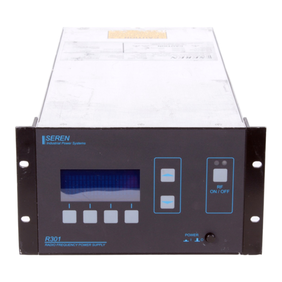
Page 7: Physical Dimensions
R301 RF POWER SUPPLY OPERATOR’S MANUAL Physical Dimensions 5.25 [133.35] SEREN Industrial Power Systems 3.75 [95.25] ON / OFF 1.50 [38.10] POWER R301 RADIO FREQUENCY POWER SUPPLY 0.00 [0.00] Front View, R301 RF Power Supply Dimensions in Inch [mm] 5.25 [133.35] 0.00 [0.00]... - Page 8 R301 RF POWER SUPPLY OPERATOR’S MANUAL 5.25 [133.35] RF OUT 4.32 [109.60] POWER 2.62 [66.47] 1.86 [47.12] 0.89 [22.50] 0.00 [0.00] Rear View, R301 RF Power Supply Dimensions in Inch [mm] Page 7 Seren IPS Inc. 6100130000 Rev. 0.05...
-
Page 9: Installation
Installation: Recommended mounting: The R301 RF Power Supply is designed for placement on a tabletop or on a shelf within an equipment rack, with another ½ Rack 3U piece of equipment, in a clean environment. The table or equipment rack must be capable of supporting the full weight of the unit. - Page 10 The signal present at this connector is the same frequency the R301 is using to produce its RF output. This signal can be used as a frequency signal source for other RF Power supplies in a multiple RF power supply system.
-
Page 11: Front Panel Controls And Display
Item Name Description Program/Run Toggles the R301 RF Power Supply between the RUN mode and PROGRAM mode. In Program mode, display line 3 changes to show Programmable Menu Entry Options. The button legend changes from “PGM” to “RUN” when in the Program mode. - Page 12 R301 RF POWER SUPPLY OPERATOR’S MANUAL Display The front panel display shows the operational status of the R301 RF Power Supply and provides legends for the keypad. LINE 1 SET: 0W REF: LINE 2 PANEL PANEL CONTROL LINE 3 DOWN...
-
Page 13: Operation
R301 RF POWER SUPPLY OPERATOR’S MANUAL Operation Front panel operation of the R301 RF Power Supply is simple. This section describes the use and operation of the front panel controls in a “how to…” manner. Refer to the front panel illustration on the previous page for item references. - Page 14 Supply is powered down – it will power-up in the same mode. Leveling Mode: The leveling mode is the method the R301 uses to regulate its output power. There are three (3) leveling mode selections. · The “PWR” (power) leveling mode uses the R301’s internal power sensor to regulate the RF output power.
- Page 15 R301 RF POWER SUPPLY OPERATOR’S MANUAL · The “VOLTAGE” (VLT) leveling mode uses an external feedback voltage (derived from a Voltage Probe in the processing system’s matching network or processing chamber) to regulate the RF output power. To select a leveling mode, follow the directions below: Forward (FWD) Power Leveling mode: 1.
- Page 16 8. Press the “RUN” button (item 1) to exit the programming menu. Set Output Power Level 1. Ensure the R301 RF Power Supply is in the “RUN” mode – the legend above the Program/Run button (item 1) is “PGM”. 2. Use the Value Up button (item 5) or Value Down button (item 6) to adjust the power setpoint (SET: XXXW on the front panel display) to the desired power level.
-
Page 17: Analog Interface Operation
3. Select ANALOG control mode. Note: The ANALOG control mode only needs to be selected once. The R301 RF power supply will retain the selected control mode during a power-off/power-on cycle. - Page 18 R301 RF POWER SUPPLY OPERATOR’S MANUAL Note: the RFON* signal is edge triggered. A transition from a TTL “high” to TTL “low” logic state must occur to enable the RF output. This prevents accidental enabling of the RF output when the RF power supply...
-
Page 19: Serial Interface Operation
Remain in the programming environment, do not press the RUN button. 4. Select the BAUD rate: Serial control must be selected before attempting to select the baud rate. If the R301 is set for PANEL or ANALOG control mode, the baud rate selection will not appear in the programming menu. - Page 20 Assert SERIAL control mode. Command: ***<cr> Response: <prompt><cr> Query RF Power Supply Status Returns the current status of the R301 RF Power Supply, in the form of a mapped string, terminated with <cr>. Command: Q<cr> Response: XXXXXXX_aaaa_bbbb_ccc_dddd<cr> Where: aaaa is the setpoint, in Watts...
- Page 21 Character #7: Not Used/reserved Query the Control Voltage Responds with the external feedback (or DC Bias) Voltage, with Probe Attenuation and scaling factors applied. Because The R301 only has one external feedback channel, this command is identical to the “0?”...
- Page 22 Response: <prompt><cr> Select LOAD POWER leveling Configures the R301 to deliver a constant Net Power to the load. Net Power = (Forward Power – Reflected Power). The power setpoint is set by the front panel controls or the “W” serial command.
- Page 23 R301 RF POWER SUPPLY OPERATOR’S MANUAL Response: <prompt><cr> Disable the RF Output Command: S<cr> Response: <prompt><cr> Set the Power Setpoint Command: XXXX_W<cr> Where XXXX is the desired setpoint, in 1-Watt increments, 1 to 4 digits. Response: <prompt><cr> Set the Voltage Setpoint Command: XXXX_V<cr>...
- Page 24 R301 RF POWER SUPPLY OPERATOR’S MANUAL NOECHO Disable ECHO mode Suppresses the echo of commands. Response for accepted (acknowledged) commands is <prompt><cr>. Response for invalid commands is N<cr> Command: NOECHO<cr> Response: <prompt><cr> Page 23 Seren IPS Inc. 6100130000 Rev. 0.05...
- Page 25 Returns the Control Voltage, with scaling and probe attenuation factors applied. Response: -XXXX<cr> (Negative polarity is assumed) Note: Because the R301 only has one (1) External FEEDBACK input, this command is identical to the “0” command. Query Power Leveling Mode LVL?<cr>...
- Page 26 R301 RF POWER SUPPLY OPERATOR’S MANUAL Send Description/Comment Select VOLTAGE DR<cr> Sets the Analog Interface connector CONTROL mode FEEDBACK signal as the feedback source for regulating the RF output level. Response: <prompt><cr> Select POWER CONTROL IR<cr> Sets the unit’s internal power sensor as...
- Page 27 R301 RF POWER SUPPLY OPERATOR’S MANUAL Send Description/Comment Response: <prompt><cr> Set the Process Pulse Low XXXX_LP<cr> XXXX is the process pulse low power Power Setpoint setpoint, in Watts. 1 to 4 digits. Response: <prompt><cr> Set the Process Pulse High XXXX_HP<cr>...
-
Page 28: Configuring Programmable Parameters
“ENT” button (item 4) also saves the programmable parameter. The programmable parameters are saved in the R301 RF Power Supply’s memory and are recalled upon power-on PROGRAMABLE PARAMAETER REFERENCE CHART: Programmable parameters intended for use by equipment operators are listed below. - Page 29 R301 RF POWER SUPPLY OPERATOR’S MANUAL LEVEL PARAMETER DISPLAY LINE 3 OPTION Output Power Range Select HIGH RANGE 0-300W Output* LOW RANGE 0-30W Output Exciter Mode (Frequency EXCITER- MASTER Internal Source* Source) Select EXCITER- SLAVE External CEX Input Maximum Output Power...
-
Page 30: Programmable Parameter Details
Level Parameter Detail Control Source: Selects the interface used as the control source for the R301 RF power supply. Panel Control Selects the front panel keypad as the control source. RF ON/OFF and power setpoint commands from the analog interface are ignored. Serial interface commands, with the exception of the “SERIAL”... - Page 31 Level Parameter Detail POWER CONTROL: Uses the R301’s internal power sensor as the feedback source for regulating the RF output level. Line 1 of the front panel display indicates forward power setpoint, in Watts, when the RF output is off, indicates Forward or Load power when the RF output is enabled.
- Page 32 Used when regulating the unit’s RF output with an external feedback signal. Setting the attenuation factor to match the external system’s probe attenuation factor allows the R301 RF power supply to directly display the feedback signal in Volts. External feedback voltages are derived from the processing system and can range from tens of Volts to thousands of Volts.
- Page 33 DISABLE MATCH PRESET Disables Matching Network Preset feature (Factory default setting) Note: This feature is designed for use with the Seren IPS Inc. MC2 matching network controller and AT-Series automatic matching networks. The MC2 controller, AT-Series matching networks, and interface cabling are not supplied with the R301 product and must be purchased separately.
- Page 34 (0 to +5.0VDC) is present at the analog interface connector’s FWD MON (forward power monitor) signal (pin 10). Note: this feature designed for use with the Seren IPS Inc. MC2 matching network controller and AT-Series automatic matching networks.
-
Page 35: Rear Panel Controls And Connections
RATINGS PLATE OR CONSULT A QUALIFIED ELECTRICIAN BEFORE CONNECTING THE R301 RF POWER SUPPLY TO MAINS POWER. CONNECTING TO THE WRONG MAINS VOLTAGE MAY DAMAGE THE R301 RF POWER SUPPLY AND VOID THE WARRANTY. Page 34 Seren IPS Inc. 6100130000 Rev. 0.05... -
Page 36: Cex In Connector
Input Impedance: 100K Ohm Option. Permits the R301 to use a negative polarity voltage probe signal from a passive probe (such as an MM-Series or PM-Series matching network) for external RF output regulation feedback (voltage control). Connect a negative polarity probe signal to the DCP connector and connect Analog Interface connector pin 25 (INVPROBE output) to Analog Interface connector pin 24 (FEEDBACK input). -
Page 37: Analog Interface Connector Pin List And Functional Description
R301 RF POWER SUPPLY OPERATOR’S MANUAL When in Slave mode, the R301 RF Power Supply uses the common exciter input as its frequency source. 7. Fan Exhaust Keep fan exhaust free of obstructions, dust and dirt. When the R301 RF Power Supply is mounted in an enclosure or equipment rack, ensure there is an adequate air intake and hot air exhaust. - Page 38 R301 RF POWER SUPPLY OPERATOR’S MANUAL SIGNAL NAME DESCRIPTION This signal is active in Panel, Analog, or Serial control modes INTERLOCK External Interlock. TTL – compatible input, active low, with an internal pull-up resistor. A contact closure between pin 2 and pin 15 or a TTL “low” signal applied to pin 2 is required before RF output can be enabled.
- Page 39 Power Alarm” in the Programmable Parameters section for details. The RFENABLED* output signal may also be used to pre- position Seren IPS Inc. AT-Series Matching Networks. Refer to “Matching Network Preset Mode”, “Tune Capacitor Preset Position”, and “Load Capacitor Preset Position” in the Programmable Parameters section.
- Page 40 R301 RF POWER SUPPLY OPERATOR’S MANUAL SIGNAL NAME DESCRIPTION pre-position Seren IPS Inc. AT-Series Matching Networks. Refer to “Matching Network Preset Mode”, “Tune Capacitor Preset Position”, and “Load Capacitor Preset Position” in the Programmable Parameters section. Measure monitor voltage with respect to pin 23 (REFRET).
- Page 41 R301 RF POWER SUPPLY OPERATOR’S MANUAL SIGNAL NAME DESCRIPTION chassis ground. GNDI Ground return for pins 3,4,5,6,7,8,13,19. Internally connected to chassis ground. RL-IN Remote Limit input. Analog input, 0 to +5VDC range. Use pin 16,17,18, or 21 (GNDI) for return reference.
-
Page 42: Typical Interface Circuits
R301 RF POWER SUPPLY OPERATOR’S MANUAL TYPICAL INTERFACE CIRCUITS Figures 1 through 5 illustrate the typical circuits used in the R301 RF Power Supply’s Analog Interface. RFENABLED* Output Circuit: RF output status signal. Active low, open collector output. 12VDC maximum, 15mA maximum current sink, 150mW maximum power dissipation. - Page 43 R301 RF POWER SUPPLY OPERATOR’S MANUAL Figure 2: TTL-Compatible Input Circuits SETPOINT Input Circuit High-impedance, high Common-Mode Rejection Ratio, differential analog input. Input voltage range is software selectable 0 to +5.0VDC or 0 to +10.0VDC via the front panel controls. NOTE: The setpoint return signal (GNDI, pin 16, 17, 18, or 21) MUST be referenced to common or ground at the setpoint voltage source (system controller) or the RF output power will behave erratically.
-
Page 44: Monitor Output
R301 RF POWER SUPPLY OPERATOR’S MANUAL MONITOR Output Circuit Analog output, selectable 0 to +5VDC or 0 to +10VDC range via front panel controls. Normal function is forward or reflected power monitoring, but can be configured to pre- position Seren IPS Inc. AT-Series Matching Networks. -
Page 45: Serial Interface Connector Pin List And Functional Description
R301 RF POWER SUPPLY OPERATOR’S MANUAL 9. Serial Interface Connector The serial interface provides remote control and monitoring of the R301 RF Power Supply via a computer. Serial interface protocol is RS-232. Baud rates are selected via the front panel. -
Page 46: Typical Interface Connections
R301 RF POWER SUPPLY OPERATOR’S MANUAL TYPICAL INTERFACE CONNECTIONS Analog Control There are many possible analog interface wiring schemes. Basic analog interface connections are diagrammed below. Refer to the Analog Interface Connector pin list in the Rear Panel Controls and Connections section for signal details. -
Page 47: Probe Inverter Option Connections
12 and 24) only accepts a positive (+) polarity signal. The Probe Inverter feature allows the R301 RF Power Supply to utilize a negative polarity feedback signal. Connect the negative polarity external feedback signal to the rear panel “DCP” BNC connector and connect Analog Interface connector pin 24 to pin 25. - Page 48 (purchased separately). In this application, there is no connection between the R301’s Analog Interface connector pins 24 and 25, and there is no connection to the R301’s rear panel PROBE connector. The external feedback signal is derived in the AT-series matching network, via a DC Probe circuit.
-
Page 49: Typical System Configuration
A basic plasma processing system configuration is diagrammed below. Other system configurations are possible. For assistance with system configuration issues, contact the Seren IPS Inc. customer service department or a Seren IPS Inc. service depot. Coaxial cables, control cables, matching networks, matching network controllers, and plasma system equipment are not supplied with the R301 RF Power Supply. -
Page 50: Maintenance
R301 RF Power Supply. Cleaning: DO NOT clean the R301 RF Power Supply when AC Mains power is applied to the unit or when the R301 unit is connected to the AC mains. The exterior of the RF power supply may be cleaned with a soft cloth, dampened with soap and water or a mild solvent, such as alcohol. -
Page 51: Problem Solving
The following chart lists some conditions that may occur and the recommended solutions. Follow the suggested solutions until the problem is corrected. If the problem persists, please contact Seren IPS Inc. customer service or a Seren IPS Inc. service representative. Condition... - Page 52 R301 RF POWER SUPPLY OPERATOR’S MANUAL Condition Suggested Solution source signal. Ensure the setpoint signal is connected to the Analog Interface Connector with shielded cable. The text “EXT” is shown on The Analog Interface “INTERLOCK” signal is at a TTL line 2 of the front panel “HIGH”...
-
Page 53: Technical Data
R301 RF POWER SUPPLY OPERATOR’S MANUAL Technical Data AC Mains Voltage Taps: 98V, 115V, 208V, or 220V; Single-phase, factory configured. Input Power Specify desired AC mains voltage at time of order. Voltage taps are set to the most appropriate setting at the factory. - Page 54 R301 RF POWER SUPPLY OPERATOR’S MANUAL Spurious Radiation: Designed to meet or exceed FCC requirements. Harmonics: -50dBc Noise, Hum, and Ripple: -50dBc Environment: Operating Temperature, Ambient: 0 to +40°C Operating Relative Humidity: 10% to 90%, non-condensing Cooling: Forced Air, 110 CFM...
-
Page 55: Seren 1 Year Limited Warranty
SEREN I.P.S. modification or upgrade. Improper return shipping, packaging, or shipping damage is not covered. SEREN I.P.S. will not be liable for any incidental or consequential damages resulting from your use or inability to use your RF Power Supply. IF YOU HAVE A PROBLEM The first step is to contact your system vendor. -
Page 56: Glossary Of Terms
R301 RF POWER SUPPLY OPERATOR’S MANUAL Glossary of Terms Amperes, a measurement unit of current Alternating Current ANLG Abbreviation, “Analog” Chamber Industry term for a vacuum chamber used in plasma processing equipment. Common Exciter A method of using an external frequency source to synchronize... - Page 57 R301 RF POWER SUPPLY OPERATOR’S MANUAL Radio Frequency RF Generator Industry term for Radio Frequency Power Supply Transistor-Transistor Logic Tuner Industry term for an impedance matching network Volts, Alternating Current Volts, Direct Current Abbreviation, “VOLTAGE” Voltage Control Using an external DC voltage derived from the processing...
-
Page 58: Revision History
R301 RF POWER SUPPLY OPERATOR’S MANUAL Revision History: Revision Date Revision Description 0.01 1019/03 Preliminary 0.02 10/27/03 Updated Table of Contents, Analog Interface, and Technical Data Sections. 0.03 12/18/03 Deleted “A” from model number, updated illustrations. 0.04 4/1/04 Corrected Typical Interface Connection diagram, added maximum current and inrush current to technical specifications.
Need help?
Do you have a question about the R301 and is the answer not in the manual?
Questions and answers