Table of Contents
Advertisement
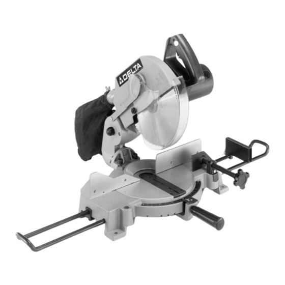
10" Compound Miter Saw
(Model 36-220)
PART NO. 900327 - 01-01-01
Copyright © 2001 Delta Machinery
To learn more about DELTA MACHINERY
ESPAÑOL: PÁGINA 23
visit our website at: www.deltamachinery.com.
For Parts, Service, Warranty or other Assistance,
1-800-223-7278 (
1-800-463-3582).
please call
In Canada call
Advertisement
Table of Contents

Related Manuals for Delta 36-220


Summary of Contents for Delta 36-220
- Page 1 10" Compound Miter Saw (Model 36-220) PART NO. 900327 - 01-01-01 Copyright © 2001 Delta Machinery To learn more about DELTA MACHINERY ESPAÑOL: PÁGINA 23 visit our website at: www.deltamachinery.com. For Parts, Service, Warranty or other Assistance, 1-800-223-7278 ( 1-800-463-3582).
-
Page 2: Safety Rules
If you have any questions rela- tive to a particular application, DO NOT use the machine until you have first contacted Delta to determine if it can or should be performed on the product. -
Page 3: Additional Safety Rules For Compound Miter Saws
ADDITIONAL SAFETY RULES FOR COMPOUND MITER SAWS 1. USE ONLY CROSS-CUTTING SAW BLADES. 18. NEVER reach around saw blade. WHEN USING CARBIDE TIPPED BLADES, MAKE SURE THEY HAVE A NEGATIVE HOOK ANGLE. DO 19. MAKE SURE blade is not contacting workpiece NOT USE BLADES WITH DEEP GULLETS AS THEY before switch is turned on. -
Page 4: Motor Specifications
CONNECTING COMPOUND MITER SAW TO POWER SOURCE Your new Compound Miter Saw is DOUBLE INSULATED to give you added safety. As a result, this saw is equipped with a two-prong plug which permits you to use any conventional 120 Volt electrical outlet without concern for main- taining a ground connection. -
Page 5: Operating Instructions
OPERATING INSTRUCTIONS FOREWORD Delta Model 36-220 is a 10" Compound Miter Saw designed to cut wood. It can crosscut up to 2- ", miter at " x ° both left and right 2- " x ", bevel at 45 °... - Page 6 ASSEMBLY SERVES AS A RETENTION MEANS FOR THE SAW ARBOR. ANY PRODUCT ADJUST- MENTS OR SERVICING, NOT COVERED BY THIS INSTRUCTION MANUAL, SHOULD BE UNDERTAK- EN ONLY BY AN AUTHORIZED DELTA SERVICE Fig. 2 REPRESENTATIVE. 1. Push down on the cuttinghead handle slightly and rotate latch (A) Fig.
- Page 7 ASSEMBLING STOCK STOP AND TABLE EXTENSIONS 1. Decide on which side of the saw table you want the stock stop (A) Fig. 5, to be, and assemble stock stop (A) onto table extension (B), as shown. NOTE: The most commonly used position of the stock stop will be on the right hand table extension, as shown.
-
Page 8: Assembling Dust Bag
ASSEMBLING ACCESSORY WORK CLAMP TO SAW 1. The work clamp (A) Fig. 9, can be used on either the right or left side of the saw base. Insert post of work clamp into the hole located on the front of the saw base, as shown. -
Page 9: Operating Controls
OPERATING CONTROLS TABLE HAZARD AREA WARNING: THE AREA INSIDE THE TWO RED LINES (A) FIG. BB, ON THE TABLE IS DESIGNATED AS A HAZARD ZONE. NEVER PLACE YOUR HANDS INSIDE THIS AREA WHILE THE TOOL IS BEING OPERATED. Fig. BB STARTING AND STOPPING SAW To turn the saw “ON”... -
Page 10: Rotating Table For Miter Cutting
ROTATING TABLE FOR MITER CUTTING Your compound miter saw will cut any miter angle from a straight 90 degree cut-off to 47 degrees right and left. Simply loosen lock handle (A) Fig. 14, depress index lever (B) and move the control arm to the desired angle. Then tighten lock handle (A). - Page 11 LOCKING CUTTING ARM IN THE DOWN POSITION When transporting the saw, the cutting arm should always be locked in the down position. This can be accomplished by lowering the cutting arm (A) Fig. 18, and moving the locking lever (B) to the locked position, as shown.
-
Page 12: Adjusting 90 And 45 Degree Bevel Stops
ADJUSTMENTS ADJUSTING 90 AND 45 DEGREE BEVEL STOPS 1. DISCONNECT THE SAW FROM THE POWER SOURCE. 2. Loosen bevel lock handle and tilt the cutting arm all the way to the right and tighten the bevel lock handle. 3. Using a square (A) Fig. 21, place one end of the square on the table and the other end against the blade. -
Page 13: Adjusting Blade Parallel To Table Slot
ADJUSTING BLADE PARALLEL TO TABLE SLOT 1. DISCONNECT THE SAW FROM THE POWER SOURCE. 2. NOTE: This adjustment should be checked with the cutting arm moved all the way to the right (blade 90 degrees to the table). 3. Lower the cutting arm. The saw blade (A) Fig. 25, should be parallel to the left edge (B) of the table insert opening. - Page 14 7. Loosen the two fence locking screws, one of which is shown at (A) Fig. 28, and move the fence (B) all the way to the rear position, as shown. Then tighten the two fence locking screws (A). 8. Using a square, place one end of the square against the blade and the other end against the table and check to see if the fence is 90 degrees to the blade.
-
Page 15: Adjusting Downward Travel Of Saw Blade
ADJUSTING DOWNWARD TRAVEL OF SAW BLADE 1. DISCONNECT THE SAW FROM THE POWER SOURCE. 2. The downward travel of the saw blade can be limited to prevent the saw blade from contacting any metal sur- faces of the machine. This adjustment is made by loos- ening locknut (A) Fig. -
Page 16: Cutting Crown Moulding
9. Fig. 34, illustrates the work clamp (B) being used to firmly hold the workpiece against the fence. Fig. 34 10. Fig. 35, illustrates the cuttinghead tilted and the arm in a miter position for a compound miter/bevel cutting operation. Fig. -
Page 17: Auxiliary Wood Fence
Fig. 37 Fig. 38 1. Move the table to the 31-5/8 degree right miter position and lock the table in position. NOTE: A triangle indicator is provided on the miter scale to find this angle quickly. 2. Tilt the saw blade to the 33-7/8 degree left bevel position and tighten bevel lock handle. NOTE: A triangle indicator is provided on the bevel scale to find this angle quickly. -
Page 18: Changing Blade
MAINTENANCE CHANGING THE BLADE WARNING: USE ONLY CROSS-CUTTING SAW BLADES. WHEN USING CARBIDE TIPPED BLADES, MAKE SURE THEY HAVE A NEGATIVE HOOK ANGLE. DO NOT USE BLADES WITH DEEP GULLETS AS THEY CAN DEFLECT AND CONTACT GUARD. 1. DISCONNECT THE SAW FROM THE POWER SOURCE. -
Page 19: Brush Inspection And Replacement
BRUSH INSPECTION AND REPLACEMENT CAUTION: BEFORE INSPECTING BRUSHES, DIS- CONNECT THE MACHINE FROM THE POWER SOURCE. Brush life varies. It depends on the load on the motor. Check the brushes after the first 50 hours of use for a new machine or after a new set of brushes has been installed. -
Page 20: Parts, Service Or Warranty Assistance
Two Year Limited Warranty Delta will repair or replace, at its expense and at its option, any Delta machine, machine part, or machine accessory which in normal use has proven to be defective in workmanship or material, provided that the customer returns the product pre- paid to a Delta factory service center or authorized service station with proof of purchase of the product within two years and provides Delta with reasonable opportunity to verify the alleged defect by inspection. - Page 21 NOTES...
- Page 22 NOTES...
- Page 23 Delta Distributor, Authorized • Service Center, or Porter-Cable Delta Factory Service Center. If you do not have access to any of these, call 888-848-5175 and you will • be directed to the nearest Porter-Cable Delta Factory Service Center. Las Estaciones de Servicio Autorizadas están ubicadas en muchas grandes ciudades.
Need help?
Do you have a question about the 36-220 and is the answer not in the manual?
Questions and answers
Is this cast iron or aluminum?