Table of Contents
Advertisement
Advertisement
Table of Contents

Related Manuals for Asus P4C800


Summary of Contents for Asus P4C800
- Page 1 P4C800 User Guide...
- Page 2 Product warranty or service will not be extended if: (1) the product is repaired, modified or altered, unless such repair, modification of alteration is authorized in writing by ASUS; or (2) the serial number of the product is defaced or missing.
-
Page 3: Table Of Contents
Notices ................... vi Safety information ................. vii About this guide ................viii ASUS contact information ............... x P4C800 specifications summary ............ xi Chapter 1: Product introduction 1.1 Welcome! ................1-1 1.2 Package contents ............... 1-1 1.3 Special features ..............1-2 1.3.1... - Page 4 Creating a bootable floppy disk ......4-1 4.1.2 Using AFUDOS to update the BIOS ...... 4-1 4.1.3 Using ASUS EZ Flash to update the BIOS .... 4-3 4.1.4 Recovering the BIOS with CrashFree BIOS 2 ..4-4 4.2 BIOS Setup program ............4-6 4.2.1...
- Page 5 5.2.1 Running the support CD ........5-1 5.2.2 Drivers menu ............5-2 5.2.3 Utilities menu ............5-3 5.2.4 ASUS Contact Information ........5-4 5.2.5 Other information ........... 5-5 5.3 Software information ............5-7 5.3.1 ASUS Update ............5-7 5.3.2 ASUS MyLogo2™ ..........5-8 5.3.3...
-
Page 6: Notices
Notices Federal Communications Commission Statement This device complies with FCC Rules Part 15. Operation is subject to the following two conditions: • This device may not cause harmful interference, and • This device must accept any interference received including interference that may cause undesired operation. -
Page 7: Safety Information
Safety information Electrical safety • To prevent electrical shock hazard, disconnect the power cable from the electrical outlet before relocating the system. • When adding or removing devices to or from the system, ensure that the power cables for the devices are unplugged before the signal cables are connected. -
Page 8: About This Guide
How this guide is organized This manual contains the following parts: • Chapter 1: Product introduction This chapter describes the features of the P4C800 motherboard. It includes brief descriptions of the special attributes of the motherboard and the new technology it supports. -
Page 9: Conventions Used In This Guide
1. ASUS Websites The ASUS websites worldwide provide updated information on ASUS hardware and software products. The ASUS websites are listed in the ASUS Contact Information on page x. 2. Optional Documentation Your product package may include optional documentation, such as warranty flyers, that may have been added by your dealer. -
Page 10: Asus Contact Information
Technical Support Support Fax: +1-510-608-4555 General Support: +1-502-933-8713 Web Site: www.asus.com Support Email: tsd@asus.com ASUS COMPUTER GmbH (Germany and Austria) Address: Harkortstr. 25, 40880 Ratingen, BRD, Germany General Email: sales@asuscom.de (for marketing requests only) General Fax: +49-2102-9599-31 Technical Support Support Hotline:... -
Page 11: P4C800 Specifications Summary
P4C800 specifications summary ® ® Socket 478 for Intel Pentium 4/Celeron with speeds up to 3.2+ GHz On-die 512KB/256KB L2 cache with full speed Supports Intel ® Hyper-Threading Technology New power design supports next generation Intel Prescott CPU Chipset Intel 875P MCH... - Page 12 Serial port 2 (COM2) connector BIOS features 4Mb Flash ROM, AMI BIOS, PnP, DMI2.0, WfM2.0, SM BIOS2.3, Multi-language BIOS, ASUS EZ Flash, CrashFree BIOS 2, ASUS C.P.R., ASUS Q-Fan, ASUS MyLogo2, ASUS Instant Music Industry standard PCI 2.2, PCI 2.3, USB 2.0 Manageability WfM 2.0.
-
Page 13: Chapter 1: Product Introduction
Chapter 1 This chapter describes the features of the P4C800 motherboard. It includes brief explanations of the special attributes of the motherboard and the new technology it supports. Product introduction... - Page 14 Chapter summary Welcome! ............1-1 Package contents .......... 1-1 Special features ..........1-2 Motherboard overview ........1-6 ASUS P4C800 motherboard...
-
Page 15: Welcome
Welcome! Thank you for buying the ASUS P4C800 motherboard! ® The ASUS P4C800 motherboard delivers a host of new features and latest technologies making it another standout in the long line of ASUS quality motherboards! ® ® The motherboard incorporates the Intel... -
Page 16: Special Features
Special features 1.3.1 Product highlights Latest processor technology ® ® The motherboard supports the latest Intel Pentium 4 Processor via a 478-pin surface mount ZIF socket. The Pentium 4 processor with 512KB L2 cache includes a 800/533/400 MHz system bus and features the Intel Hyper-Threading Technology and new power design that allow up to 3.2+GHz core frequencies. - Page 17 This protection eliminates the need to buy a replacement ROM chip. See page 4-4. ASUS Q-Fan technology The ASUS Q-Fan technology smartly adjusts the fan speeds according to the system loading to ensure quiet, cool, and efficient operation. ASUS P4C800 motherboard user guide...
-
Page 18: Asus Mylogo2
ASUS EZ Flash BIOS With the ASUS EZ Flash, you can easily update the system BIOS even before loading the operating system. No need to use a DOS-based utility or boot from a floppy disk. -
Page 19: Value-Added Solutions
ASUS Update This utility allows you to update the motherboard BIOS through a user-friendly interface. Connect to the Internet then to the ASUS FTP site nearest you to obtain the latest BIOS version for your motherboard. ASUS P4C800 motherboard user guide... -
Page 20: Motherboard Overview
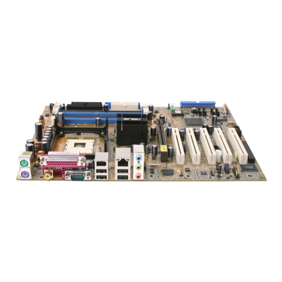
1.4.1 Major components The following are the major components of the P4C800 motherboard as pointed out in the picture on page 1-7. CPU socket 18. PS/2 mouse port North Bridge controller 19. - Page 21 ASUS P4C800 motherboard user guide...
-
Page 22: Core Specifications
1.4.2 Core specifications CPU socket. A 478-pin surface mount, Zero Insertion Force (ZIF) socket ® ® for the Intel Pentium 4 Processor, with 800/533/400 MHz system bus that allows 6.4GB/s, 4.3GB/s, and 3.2GB/s data transfer rates, respectively. The socket will support the Intel Prescott CPU when available. - Page 23 PS/2 mouse port. This green 6-pin connector is for a PS/2 mouse. Parallel port. This 25-pin port connects a parallel printer, a scanner, or other devices. RJ-45 port. This port allows connection to a Local Area Network (LAN) through a network hub. ASUS P4C800 motherboard user guide...
- Page 24 Line In jack. This Line In (light blue) jack connects a tape player or other audio sources. In 6-channel mode, the function of this jack becomes Rear Speaker Out. Line Out jack. This Line Out (lime) jack connects a headphone or a speaker.
-
Page 25: Chapter 2: Hardware Information
Chapter 2 This chapter describes the hardware setup procedures that you have to perform when installing system components. It includes details on the switches, jumpers, and connectors on the motherboard. Hardware information... - Page 26 Chapter summary Motherboard installation ....... 2-1 Motherboard layout ........2-2 Before you proceed ........2-3 Central Processing Unit (CPU) ..... 2-4 System memory ........... 2-10 Expansion slots ........... 2-14 Jumpers ............2-19 Connectors ........... 2-22 ASUS P4C800 motherboard...
-
Page 27: Motherboard Installation
Place nine (9) screws into the holes indicated by circles to secure the motherboard to the chassis. Do not overtighten the screws! Doing so may damage the motherboard. Place this side towards the rear of the chassis ASUS P4C800 motherboard user guide... -
Page 28: Motherboard Layout
Top:Line In Controller Center:Line Out Hub (MCH) Below:Mic In ® Accelerated Graphics Port (AGP_PRO) PCI1 USB56 SMB20 CHA_FAN USBPW78 PCI2 USBPW56 AD1985 CODEC P4C800 Intel ICH5R USB78 PCI3 SPDIF_OUT FP_AUDIO SATA2 SATA1 PCI4 GAME MODEM PCI5 CHASSIS PANEL WIFI COM2... -
Page 29: Before You Proceed
® SB_PWR P4C800 Standby Powered P4C800 Onboard LED Power ASUS P4C800 motherboard user guide... -
Page 30: Central Processing Unit (Cpu)
Central Processing Unit (CPU) 2.4.1 Overview The motherboard comes with a surface mount 478-pin Zero Insertion Force (ZIF) socket. The socket is designed for the Intel ® Pentium ® Processor in the 478-pin package with 512KB L2 cache. The Pentium 4 ®... -
Page 31: Installing The Cpu
90°-100° angle. Socket Lever 90 - 100 Make sure that the socket lever is lifted up to 90°-100° angle, otherwise the CPU does not fit in completely. ASUS P4C800 motherboard user guide... - Page 32 3. Position the CPU above the Gold Mark socket such that its marked corner matches the base of the socket lever. 4. Carefully insert the CPU into the socket until it fits in place. The CPU fits only in one correct orientation. DO NOT force the CPU into the socket to prevent bending the pins and damaging the CPU! 5.
-
Page 33: Installing The Heatsink And Fan
Your boxed Intel Pentium 4 Processor package should come with installation instructions for the CPU, heatsink, and the retention mechanism. If the instructions in this section do not match the CPU documentation, follow the latter. ASUS P4C800 motherboard user guide... - Page 34 2. Position the fan with the retention mechanism on top of the heatsink. Align and snap the four hooks of the retention mechanism to the holes on each corner of the module base. Make sure that the fan and retention mechanism assembly perfectly fits the heatsink and module base, otherwise you cannot snap the hooks into the holes.
-
Page 35: Connecting The Cpu Fan Cable
CPU fan cable to the connector on the motherboard labeled CPU_FAN. CPU Fan Connector (CPU_FAN) Don’t forget to connect the CPU fan connector! Hardware monitoring errors may occur if you fail to plug this connector. ASUS P4C800 motherboard user guide... -
Page 36: System Memory
The following figure illustrates the location of the DDR DIMM sockets. ® P4C800 P4C800 184-Pin DDR DIMM Sockets 2.5.2 Memory configurations You may install 64MB, 128MB, 256MB, 512MB, and 1GB DDR DIMMs into the DIMM sockets using the memory configurations in this section. - Page 37 800 MHz PC3200/PC2700*/PC2100 400/333*/266 MHz 533 MHz PC2700/PC2100 333/266 MHz 400 MHz PC2100 266 MHz *When using 800MHz CPU FSB, PC2700 DDR DIMMs may run only at 320MHz (not 333MHz) due to chipset limitation. ASUS P4C800 motherboard user guide 2-11...
- Page 38 ADATA MDOAD5F3G315B1ECZ ADATA ADD8608A8A-5B 256MB ADATA MDOSS6F3G31JB1EAE Samsung K4H560838D-TCC4 256MB ADATA MDOWB5F3G316B1EAE Winbond W942508CH-5 Obtain DDR DIMMs only from ASUS qualified vendors for better system performance. Visit the ASUS website (www.asus.com) for the latest QVL. 2-12 Chapter 2: Hardware information...
-
Page 39: Installing A Dimm
DIMM. Support the DIMM lightly with your fingers when pressing the retaining clips. The DIMM might get damaged when it flips out with extra force. 2. Remove the DIMM from the socket. ASUS P4C800 motherboard user guide 2-13... -
Page 40: Expansion Slots
Expansion slots In the future, you may need to install expansion cards. The motherboard has five PCI slots, one Accelerated Graphics Port (AGP) Pro slot, and a Wi-Fi slot. The following sub-sections describe the slots and the expansion cards that they support. Make sure to unplug the power cord before adding or removing expansion cards. -
Page 41: Standard Interrupt Assignments
When using PCI cards on shared slots, ensure that the drivers support “Share IRQ” or that the cards do not need IRQ assignments. Otherwise, conflicts will arise between the two PCI groups, making the system unstable and the card inoperable. ASUS P4C800 motherboard user guide 2-15... -
Page 42: Pci Slots
2.6.3 PCI slots There are five 32-bit PCI slots on this motherboard. The slots support PCI cards such as a LAN card, SCSI card, USB card, and other cards that comply with PCI specifications. The PCI 5 slot and the Wi-Fi slot may not be used at the same time. 2-16 Chapter 2: Hardware information... -
Page 43: Agp Pro Slot
3.3V AGP cards. ® P4C800 Keyed for 1.5v P4C800 Accelerated Graphics Port (AGP) If installing the ATi 9500 or 9700 Pro Series VGA cards, use only the card version PN xxx-xxxxx-30 or later, for optimum performance and overclocking stability. -
Page 44: Wi-Fi Slot
2.6.5 Wi-Fi slot The Wi-Fi (Wireless Fidelity) slot will support the ASUS Wi-Fi module when available. Visit the ASUS website (www.asus.com) for product updates. The Wi-Fi slot conforms to the Institute of Electrical and Electronics Engineers (IEEE) 802.11b standard for wireless devices operating in the 2.4 GHz frequency band. -
Page 45: Jumpers
(jumper caps on) to disable the feature. If you wish to install PCI devices that comply with SMBus 2.0 specification, remove the jumper caps to enable the SMBus 2.0 feature. ® SMB20 P4C800 P4C800 SMBus 2.0 Setting ASUS P4C800 motherboard user guide 2-19... - Page 46 Normal Clear CMOS (Default) P4C800 Clear RTC RAM You do not need to clear the RTC when the system hangs due to overclocking. For system failure due to overclocking, use the C.P.R. (CPU Parameter Recall) feature. Shut down and reboot the system so BIOS can automatically reset parameter settings to default values.
- Page 47 (Default) P4C800 USBPW78 USBPW56 +5VSB P4C800 USB Device Wake Up (Default) 1. The USB device wake-up feature requires a power supply that can provide 500mA on the +5VSB lead for each USB port. Otherwise, the system would not power up.
-
Page 48: Connectors
NOTE: Orient the red markings on ® the floppy ribbon cable to PIN 1. P4C800 P4C800 Floppy Disk Drive Connector 2. Power supply thermal connector (2-pin TRPWR) If your power supply has a thermal monitoring feature, connect its thermal sensor cable to this connector. - Page 49 P4C800 IDE Connectors PIN 1 Important note when using legacy OS Refer to page 2-25 on how to configure P-ATA and S-ATA devices if you installed a legacy operating system (e.g. MS-DOS, Windows 98/ Me/NT4.0). ASUS P4C800 motherboard user guide 2-23...
- Page 50 SATA2 ® SATA1 P4C800 P4C800 SATA Connectors Important notes on Serial ATA 1. In a legacy operating system (DOS, Windows 98, Windows Me, Windows NT) environment, using the Serial ATA connectors will disable the ICHR chipset support to one of the IDE channels (either primary or secondary channel).
- Page 51 BIOS item 2000/XP Onboard IDE Operate Mode Enhanced Mode Compatible Mode Compatible Mode Compatible Mode — — — Enhanced Mode Support On S-ATA — IDE Port Settings Primary P-ATA+S-ATA Sec. P-ATA+S-ATA P-ATA Ports Only ASUS P4C800 motherboard user guide 2-25...
- Page 52 By default, the pins labeled “Chassis Signal” and “Ground” are shorted with a jumper cap. If you wish to use the chassis intrusion detection feature, remove the jumper cap from the pins. CHASSIS ® P4C800 (Default) P4C800 Chassis Alarm Lead 2-26 Chapter 2: Hardware information...
- Page 53 S/PDIF audio module. Connect one end of the S/PDIF audio cable this connector and the other end to the S/PDIF module. The S/PDIF module is purchased separately. SPDIF_OUT ® P4C800 P4C800 Digital Audio Connector ASUS P4C800 motherboard user guide 2-27...
- Page 54 The system may become unstable or may not boot up if the power is inadequate. ATX12V1 ATXPWR1 +12V DC +3.3VDC +3.3VDC -12.0VDC +3.3VDC PS_ON# +5.0VDC +12V DC ® +5.0VDC -5.0VDC PWR_OK P4C800 +5.0VDC +5VSB +5.0VDC +12.0VDC P4C800 ATX Power Connector 2-28 Chapter 2: Hardware information...
- Page 55 GAME/MIDI cable to this connector. The GAME/MIDI port on the module connects a joystick or a game pad for playing games, and MIDI devices for playing or editing audio files. The USB 2.0/GAME module is purchased separately. ® P4C800 GAME P4C800 Game Connector ASUS P4C800 motherboard user guide 2-29...
- Page 56 USB 2.0 ports that support the next generation USB peripherals such as high resolution cameras, scanners, and printers. The USB 2.0/GAME module is purchased separately. ® P4C800 USB56 USB78 P4C800 USB 2.0 Header 2-30 Chapter 2: Hardware information...
- Page 57 ® FP_AUDIO P4C800 P4C800 Front Panel Audio Connector 14. Serial port 2 connector (10-1 pin COM2) This connector accommodates a second serial port using an optional serial port bracket. Connect the bracket cable to this connector then install the bracket into a slot opening at the back of the system chassis.
- Page 58 SMI Lead Switch* Requires an ATX power supply. P4C800 System Panel Connectors • System Power LED Lead (3-1 pin PLED) This 3-1 pin connector connects to the system power LED. The LED lights up when you turn on the system power, and blinks when the system is in sleep mode.
-
Page 59: Chapter 3: Powering Up
Chapter 3 This chapter describes the power up sequence and gives information on the BIOS beep codes. Powering up... - Page 60 Chapter summary Starting up for the first time ......3-1 Powering off the computer ......3-4 ASUS P4C800 motherboard...
-
Page 61: Starting Up For The First Time
Motherboard timer not operational Keyboard controller BAT test error General exception error Display memory error CMOS shutdown register read/write error 7. At power on, hold down <Delete> to enter BIOS Setup. Follow the instructions in Chapter 4. ASUS P4C800 motherboard user guide... -
Page 62: Powering Off The Computer
Powering off the computer You must first exit the operating system and shut down the system before switching off the power. For ATX power supplies, you can press the ATX power switch after exiting or shutting down the operating system. The message “You can now safely turn off your computer”... -
Page 63: Chapter 4: Bios Setup
Chapter 4 This chapter tells how to change system settings through the BIOS Setup menus. Detailed descriptions of the BIOS parameters are also provided. BIOS setup... - Page 64 Chapter summary Managing and updating your BIOS ....4-1 BIOS Setup program ........4-6 Main menu ............4-9 Advanced menu ........... 4-14 Power menu ..........4-26 Boot menu ............ 4-31 Exit menu ............4-37 ASUS P4C800 motherboard...
-
Page 65: Managing And Updating Your Bios
4.1.2 Using AFUDOS to update the BIOS Update the BIOS using the AFUDOS.EXE utility in DOS environment. 1. Visit the ASUS website (www.asus.com) to download the latest BIOS file for your motherboard. Save the BIOS file to a bootable floppy disk. - Page 66 4. At the DOS prompt, type the command line: afudos / i<filename.rom> where “filename.rom” means the latest (or original) BIOS file that you copied to the bootable floppy disk. The screen displays the status of the update process. The BIOS information on the screen is for reference only. What you see on your screen may not be exactly the same as shown.
-
Page 67: Using Asus Ez Flash To Update The Bios
4.1.3 Using ASUS EZ Flash to update the BIOS The ASUS EZ Flash feature allows you to easily update the BIOS without having to go through the long process of booting from a diskette and using a DOS-based utility. The EZ Flash is built-in the BIOS firmware so it is accessible by simply pressing <Alt>... -
Page 68: Recovering The Bios With Crashfree Bios 2
3. Insert a floppy disk that contains the original, or the latest, BIOS file for this motherboard (P4C800B.ROM). If the BIOS file that you downloaded from the ASUS website has a different filename (e.g. P4C80011.ROM), rename it to P4C800B.ROM. The BIOS update process continues when the P4C800B.ROM is found. - Page 69 4. When the BIOS update process is complete, reboot the system. The recovered BIOS may not be the latest BIOS version for this motherboard. Visit the ASUS website (www.asus.com) to download the latest BIOS file. ASUS P4C800 motherboard user guide...
-
Page 70: Bios Setup Program
The BIOS setup screens shown in this chapter are for reference purposes only, and may not exactly match what you see on your screen. Visit the ASUS website (www.asus.com) to download the latest product and BIOS information. Chapter 4: BIOS Setup... -
Page 71: Bios Menu Screen
At the bottom right corner of a menu screen are the navigation keys for that particular menu. Use the navigation keys to select items in the menu and change the settings. Some of the navigation keys differ from one screen to another. ASUS P4C800 motherboard user guide... -
Page 72: Menu Items
Language [English] Use [+] or [-] to Primary IDE Master :[ST320413A] configure system time. Primary IDE Slave :[ASUS CD-S340] For example, selecting Main shows the Secondary IDE Master :[Not Detected] Secondary IDE Slave :[Not Detected] Third IDE Master :[Not Detected]... -
Page 73: Main Menu
Sets the type of floppy drive installed. Configuration options: [Disabled] [360K, 5.25 in.] [1.2M , 5.25 in.] [720K , 3.5 in.] [1.44M, 3.5 in.] [2.88M, 3.5 in.] 4.3.4 Language [English] This field allows you to choose the BIOS language version from the available options. ASUS P4C800 motherboard user guide... -
Page 74: Primary And Secondary Ide Master/Slave
4.3.5 Primary and Secondary IDE Master/Slave While entering Setup, BIOS auto-detects the presence of IDE devices. There is a separate sub-menu for each IDE device. Select a device item then press Enter to display the IDE device information. Primary IDE Master Select the type Device : Hard Disk... -
Page 75: Ide Configuration
(OS) that you installed. Set to Enhanced Mode if you are using native OS, such as Windows 2000/XP. Set to Compatible Mode if you are using legacy OS including MS-DOS, Windows ME/98/NT4.0. Configuration options: [Compatible Mode] [Enhanced Mode] ASUS P4C800 motherboard user guide 4-11... - Page 76 Refer to the section “Parallel ATA and Serial ATA device configurations” on page 2-23 for the appropriate settings of the IDE Configuration items under different operating systems. Enhanced Mode Support On [S-ATA] The default setting S-ATA allows you to use native OS on Serial ATA and Parallel ATA ports.
-
Page 77: System Information
Change Option General Help Save and Exit Exit AMI BIOS This item displays the auto-detected BIOS information. Processor This item displays the auto-detected CPU specification. System Memory This item displays the auto-detected system memory. ASUS P4C800 motherboard user guide 4-13... -
Page 78: Advanced Menu
Advanced menu The Advanced menu items allow you to change the settings for the CPU and other system devices. Take caution when changing the settings of the Advanced menu items. Incorrect field values may cause the system to malfunction. JumperFree Configuration Configure CPU. - Page 79 Allows you to adjust to a higher AGP/PCI frequency for better system performance and overclocking capability. Configuration options: [Auto] [66.66/33.33] [72.73/36.36] [80.00/40.00] Selecting a very high AGP/PCI frequency may cause the system to become unstable! If this happens, revert to the default setting. ASUS P4C800 motherboard user guide 4-15...
- Page 80 CPU VCore Voltage [Auto] Allows you to select a specific CPU VCore voltage. Configuration options: [Auto] [1.6000V] ... [1.4750V] Refer to the CPU documentation before setting the CPU VCore voltage. A very high Vcore voltage may severely damage the CPU! DDR Reference Voltage [Auto] Allows selection of the DDR SDRAM operating voltage.
-
Page 81: Cpu Configuration
This item allows you to enable or disable the processor Hyper-Threading Technology. Configuration options: [Disabled] [Enabled] The item Hyper-Threading Technology appears only if you installed an Intel Pentium 4 CPU that supports this feature. ASUS P4C800 motherboard user guide 4-17... -
Page 82: Chipset
4.4.3 Chipset The Chipset menu items allow you to change the advanced chipset settings. Select an item then press Enter to display the sub-menu. Advanced Chipset settings WARNING: Setting wrong values in the sections below may cause system to malfunction. Configure DRAM Timing by SPD [Enabled] Performance Acceleration Mode... - Page 83 Allows you to select the size of mapped memory for AGP graphic data. Configuration options: [4MB] [8MB] [16MB] [32MB] [64MB] [128MB] [256MB] Spread Spectrum [Enabled] Configuration options: [Disabled] [Enabled] ICH Delayed Transaction [Enabled] Configuration options: [Disabled] [Enabled] MPS Revision [1.1] Configuration options: [1.1] [1.4] ASUS P4C800 motherboard user guide 4-19...
-
Page 84: Onboard Devices Configuration
4.4.4 Onboard Devices Configuration OnBoard AC’97 Audio [Auto] OnBoard LAN [Enabled] OnBoard LAN Boot ROM [Disabled] Serial Port1 Address [3F8/IRQ4] Serial Port2 Address [2F8/IRQ3] Parallel Port Address [378] Parallel Port Mode [Normal] EPP Version [1.9] ECP Mode DMA Channel [DMA3] Parallel Port IRQ [IRQ7] OnBoard Game/MIDI Port... - Page 85 Allows you to select the Parallel Port IRQ. Configuration options: [IRQ5] [IRQ7] Onboard Game/MIDI Port [Disabled] Allows you to select the Game Port address or to disable the port. Configuration options: [Disabled] [200/300] [200/330] [208/300] [208/330] ASUS P4C800 motherboard user guide 4-21...
-
Page 86: Pci Pnp
4.4.5 PCI PnP The PCI PnP menu items allow you to change the advanced settings for PCI/PnP devices. The menu includes setting IRQ and DMA channel resources for either PCI/PnP or legacy ISA devices, and setting the memory size block for legacy ISA devices. Take caution when changing the settings of the PCI PnP menu items. -
Page 87: Usb Configuration
If no USB device is detected, the item shows None. USB Function [8 USB Ports] Allows you to set the number of USB ports to activate. Configuration options: [Disabled] [2 USB Ports] [4 USB Ports] [6 USB Ports] [8 USB Ports] ASUS P4C800 motherboard user guide 4-23... -
Page 88: Usb Mass Storage Device Configuration
Legacy USB Support [Auto] Allows you to enable or disable support for legacy USB devices. Setting to Auto allows the system to detect the presence of USB devices at startup. If detected, the USB controller legacy mode is enabled. If no USB device is detected, the legacy USB support is disabled. -
Page 89: Instant Music Configuration
Allows you to select the CD-ROM drive that you wish to use for the Instant Music CD playback. Configuration options: [IDE Primary Master] [IDE Primary Slave] [IDE Secondary Master] [IDE Secondary Slave] The above item appears only if you enabled the Instant Music item. ASUS P4C800 motherboard user guide 4-25... -
Page 90: Power Menu
Power menu The Power menu items allow you to change the settings for the Advanced Power Management (APM). Select an item then press Enter to display the configuration options. Suspend Mode [Auto] Configure CPU. Repost Video on S3 Resume [No] ACPI 2.0 Support [No] ACPI APIC Support... -
Page 91: Apm Configuration
Allows you to select the duty cycle in throttle mode. Configuration options: [87.5%] [75.0%] [62.5%] [50%] [37.5%] [25%] [12.5%] System Thermal [Disabled] Allows you to enable or disable the system thermal feature to generate a power management event. Configuration options: [Disabled] [Enabled] ASUS P4C800 motherboard user guide 4-27... - Page 92 Power Button Mode [On/Off] Allows the system to go into On/Off mode or suspend mode when the power button is pressed. Configuration options: [On/Off] [Suspend] Restore on AC Power Loss [Power Off] When set to Power Off, the system goes into off state after an AC power loss.
-
Page 93: Hardware Monitor
Q-Fan Control [Disabled] This item allows you to enable or disable the ASUS Q-Fan feature that smartly adjusts the fan speeds for more efficient system operation. When this field is set to [Enabled], the... - Page 94 Fan Speed Ratio [11/16] This item allows you to select the appropriate fan speed ratio for the system. The default [11/16] is the minimum fan speed ratio. Select a higher ratio if you installed additional devices and the system requires more ventilation.
-
Page 95: Boot Menu
These items specify the boot device priority sequence from the available devices. The number of device items that appear on the screen depends on the the number of devices installed in the system. Configuration options: [xxxxx Drive] [Disabled] ASUS P4C800 motherboard user guide 4-31... -
Page 96: Boot Settings Configuration
4.6.2 Boot Settings Configuration Boot Settings Configuration Allows BIOS to skip certain tests while Quick Boot [Enabled] booting. This will Quiet Boot [Enabled] decrease the time Add On ROM Display Mode [Force BIOS] needed to boot the Bootup Num-Lock [On] system. - Page 97 When set to Enabled, the system displays the message “Press DEL to run Setup” during POST. Configuration options: [Disabled] [Enabled] Interrupt 19 Capture [Disabled] When set to [Enabled], this function allows the option ROMs to trap Interrupt 19. Configuration options: [Disabled] [Enabled] ASUS P4C800 motherboard user guide 4-33...
-
Page 98: Security
4.6.3 Security The Security menu items allow you to change the system security settings. Select an item then press Enter to display the configuration options. Security Settings <Enter> to change password. Supervisor Password Not Installed <Enter> again to User Password Not Installed disable password. - Page 99 View Only allows access but does not allow change to any field. Limited allows change to only selected fields, such as Date and Time. Full Access allows viewing and changing all the fields in the Setup utility. ASUS P4C800 motherboard user guide 4-35...
-
Page 100: Change User Password
Change User Password Select this item to set or change the user password. The User Password item on top of the screen shows the default Not Installed. After you have set a password, this item shows Installed. To set a User Password: 1. -
Page 101: Exit Menu
Select this option only if you do not want to save the changes that you made to the Setup program. If you made changes to fields other than system date, system time, and password, the BIOS asks for a confirmation before exiting. ASUS P4C800 motherboard user guide 4-37... -
Page 102: Discard Changes
Discard Changes This option allows you to discard the selections you made and restore the previously saved values. After selecting this option, a confirmation appears. Select [Yes] to discard any changes and load the previously saved values. Load Setup Defaults This option allows you to load the default values for each of the parameters on the Setup menus. -
Page 103: Chapter 5: Software Support
Chapter 5 This chapter describes the contents of the support CD that comes with the motherboard package. Software support... - Page 104 Chapter summary Install an operating system ......5-1 Support CD information ........ 5-1 Software information ........5-7 Intel ® RAID for Serial ATA ......5-21 ® 3Com Virtual Cable Tester™ technology . 5-26 ASUS P4C800 motherboard...
-
Page 105: Install An Operating System
The contents of the support CD are subject to change at any time without notice. Visit the ASUS website for updates. 5.2.1 Running the support CD To begin using the support CD, simply insert the CD into your CD-ROM drive. -
Page 106: Drivers Menu
5.2.2 Drivers menu The drivers menu shows the available device drivers if the system detects installed devices. Install the necessary drivers to activate the devices. Intel Chipset Inf Update program ® This item installs the Intel Chipset INF Update Program that enables Plug-n-Play INF support for Intel chipset components. -
Page 107: Utilities Menu
This program allows you to download the latest version of the BIOS from the ASUS website. Before using the ASUS Update, make sure that you have an Internet connection so you can connect to the ASUS website. Microsoft Direct X Driver This item installs the Microsoft Direct X driver. -
Page 108: Asus Contact Information
5.2.4 ASUS Contact Information Clicking the ASUS Contact Information tab displays as stated. You may also find this information on page x of this user guide. Chapter 5: Software support... -
Page 109: Other Information
CD. Click an icon to display the specified information. Motherboard Info The window displays the general specifications of the motherboard. Browse this CD The window displays the support CD contents in graphical format. ASUS P4C800 motherboard user guide... - Page 110 Technical Support Form The window displays the ASUS Technical Support Request Form that you have to fill up when requesting technical support. Filelist The window displays the contents of the support CD and a brief description of each in text format.
-
Page 111: Software Information
This section provides details on the software applications that the motherboard supports. 5.3.1 ASUS Update The ASUS Update is a utility that allows you to update the motherboard BIOS. This utility requires an Internet connection either through a network or an Internet Service Provider (ISP). -
Page 112: Asus Mylogo2
5.3.2 ASUS MyLogo2™ The ASUS MyLogo2™ is automatically installed when you install the ASUS Update utility from the software menu. See section “5.2.3 Software menu”. Before using ASUS MyLogo2 feature, use the AFUDOS utility to make a copy of your original BIOS file, or obtain the latest BIOS version from the ASUS website. - Page 113 Your system boots with the new boot logo. Instead of starting from ASUS Update, you may also launch ASUS MyLogo2 directly from the Windows Start menu to change your BIOS boot logo. After you have modified the BIOS file with the new logo, use the ASUS Update utility to upload the new BIOS.
-
Page 114: Asus Pc Probe
5.3.3 ASUS PC Probe The ASUS PC Probe is a convenient utility to continuously monitor the vital system information, such as fan rotations, voltages, and temperatures. This utility also allows you to check other information about your computer, including hard disk space, memory usage, and CPU type, CPU speed, and internal/external frequencies through the DMI Explorer. - Page 115 Fan Monitor Shows the PC fan rotation. Fan Warning threshold adjustment (Move the slider up to increase the threshold level or down to decrease the threshold level) Voltage Monitor Shows the PC voltages. ASUS P4C800 motherboard user guide 5-11...
- Page 116 Settings Lets you set threshold levels and polling intervals or refresh times of the PC’s temperature, fan rotation, and voltages. CPU Cooling System Setup Lets you select when to enable software CPU cooling. When When CPU Overheated is selected, the CPU cooling system is enabled whenever the CPU temperature reaches the threshold value.
- Page 117 PC, such as CPU type, CPU speed, and internal/external frequencies, and memory size. Utility Lets you run programs outside of the ASUS Probe modules. To run a program, click Execute Program NOTE: This feature is currently unavailable. ASUS P4C800 motherboard user guide...
- Page 118 ASUS PC Probe Task Bar Icon Right clicking the PC Probe icon brings up a menu to open or exit ASUS PC Probe and pause or resume all system monitoring. When the ASUS PC Probe senses a problem with your PC,...
-
Page 119: Soundmax® 4 Xl Software
If the SoundMAX4 XL software is correctly installed, you will find the SoundMAX4 XL icon on the taskbar. SoundMAX4 XL icon From the taskbar, double-click on the SoundMAX4 XL icon to display the SoundMAX Control Panel. ASUS P4C800 motherboard user guide 5-15... -
Page 120: Setup Wizards
Setup wizards Use the speaker and microphone setup wizards to fine tune the gain/ attenuation of the inputs/outputs for optimal audio performance. You may launch the setup wizards by clicking the Configuration button when AudioESP detects and verifies a newly connected peripheral, or by clicking on the icon from the SoundMAX control panel. -
Page 121: Listening Environment Options
The Preferences page of the SoundMAX4 XL allows you to change various audio settings. Listening environment options The SoundMAX4 XL support several audio technologies including SoundMAX SPX™ Animated Audio, 3DPA™, MultiDrive™ 5.1, EnvironmentFC™, MacroFX/ZoomFX™, and Virtual Theater Surround. ASUS P4C800 motherboard user guide 5-17... -
Page 122: Asus Instant Music
2. Instant Music does not work if you installed and enabled an add-on sound card. 3. Instant Music only supports PS/2 keyboard. To enable ASUS Instant Music: 1. Connect the analog audio cable from the optical drive (CD-ROM, DVD- ROM, or CD-RW drive) to the 4-pin CD-In connector (labeled CD) on the motherboard. - Page 123 VOL. DOWN VOL. UP ON/OFF To guide you in using Instant Music, place the Instant Music label over the function keys on the keyboard. The Instant Music keyboard label comes with your motherboard package. ASUS P4C800 motherboard user guide 5-19...
- Page 124 Instant Music function keys (Set 2) CAPS SCROLL LOCK LOCK CD ON/OFF STOP/EJECT PLAY/PAUSE PREVIOUS NEXT VOL. DOWN VOL. UP 3. Connect speakers or a headphone to the Line Out (lime colored) port on the rear panel for audio output. You may also connect a headphone to the headphone jack on the CD-ROM drive front panel.
-
Page 125: Intel Raid For Serial Ata
4. Press <F10> to save your changes and exit the Setup utility. For more information on the Intel RAID for Serial ATA , refer to the Intel Application Accelerator (RAID Edition) User’s Manual in the motherboard support CD. See path \Manual\IAA RAID Manual.doc. ASUS P4C800 motherboard user guide 5-21... -
Page 126: Installing Serial Ata Hard Disks
5.4.2 Installing Serial ATA hard disks 1. A Serial ATA hard disk requires SATA data (4-conductor) and power cables. Make sure that you have the appropriate SATA cables before your proceed with the installation. 2. Carefully follow other hard disk installation instructions that came with the Serial ATA hard disks. -
Page 127: Creating A Raid Volume
Y when a confirmation message appears. Are you sure you want to create this volume (Y/N) 5. Scroll down to option 4. Exit and press <Enter> to exit the RAID configuration utility. Press Y when a confirmation message appears. ASUS P4C800 motherboard user guide 5-23... -
Page 128: Deleting A Raid Volume
5.4.5 Deleting a RAID Volume Take caution when deleting a RAID volume. Deleting a RAID volume erases all data on the RAID drives! Intel(R) Integrated RAID for Serial ATA - RAID Configuration Utility Copyright(C) 2003 Intel Corporation. All Rights Reserved. v3.x.x.xxxx DELETE ARRAY MENU Name Level... -
Page 129: Resetting A Raid To Non-Raid
RAID volume. WARNING: Selecting "Yes" will cause all data on any RAID disk (RAID Volume or Other RAID Disk) to be lost. Are you sure you want to destroy all RAID data (Y/N): ASUS P4C800 motherboard user guide 5-25... -
Page 130: 3Com Virtual Cable Tester™ Technology
® 3Com Virtual Cable Tester™ technology The motherboard supports the 3Com Virtual Cable Tester (VCT) technology. The VCT virtually diagnoses and reports cable faults using the Time Domain Reflectometry (TDR) tool. The VCT technology detects and reports open and shorted cables with up to 1 meter of accuracy. It also detects impedance mismatches, pair swaps, pair polarity problems, and pair skew problems of up to 64ns. - Page 131 4. Click on the (VCT) Virtual Cable Tester button to display the following screen. 5. Click on Run to execute test. If there is no cable connection problem, the Run button is grayed out and not selectable. ASUS P4C800 motherboard user guide 5-27...
- Page 132 5-28 Chapter 5: Software support...
Need help?
Do you have a question about the P4C800 and is the answer not in the manual?
Questions and answers