Table of Contents
Advertisement
Advertisement
Table of Contents

Related Manuals for Asus P4V800D-X


Summary of Contents for Asus P4V800D-X
- Page 1 P4V800D-X User Guide...
- Page 2 Product warranty or service will not be extended if: (1) the product is repaired, modified or altered, unless such repair, modification of alteration is authorized in writing by ASUS; or (2) the serial number of the product is defaced or missing.
-
Page 3: Table Of Contents
Managing and Updating Your BIOS ..........2-2 2.1.1 Creating a bootable floppy disk ........2-2 2.1.2 Using AFUDOS to copy the current BIOS ....... 2-2 2.1.3 Using AFUDOS to update the BIOS ....... 2-3 2.1.4 Using ASUS EZ Flash to update the BIOS ..... 2-5... - Page 4 Contents BIOS Setup Program ..............2-6 2.2.1 BIOS menu screen ............2-7 2.2.2 Menu bar ................. 2-7 2.2.3 Navigation keys ............... 2-7 2.2.4 Menu items ..............2-8 2.2.5 Sub-menu items .............. 2-8 2.2.6 Configuration fields ............2-8 2.2.7 Pop-up window ............... 2-8 2.2.8 Scroll bar .................
-
Page 5: Notices
Notices Federal Communications Commission Statement This device complies with FCC Rules Part 15. Operation is subject to the following two conditions: • This device may not cause harmful interference, and • This device must accept any interference received including interference that may cause undesired operation. -
Page 6: Safety Information
Safety Information Electrical safety • To prevent electrical shock hazard, disconnect the power cable from the electrical outlet before relocating the system. • When adding or removing devices to or from the system, ensure that the power cables for the devices are unplugged before the signal cables are connected. -
Page 7: About This Guide
ASUS websites The ASUS websites worldwide provide updated information on ASUS hardware and software products. Refer to the ASUS contact information. Optional documentation Your product package may include optional documentation, such as warranty flyers, that may have been added by your dealer. These documents are not... -
Page 8: P4V800D-X Specifications Summary
Supports up to eight USB 2.0 ports Special features Wake on Ring, LAN, USB, Keyboard & Mouse STR (Suspend-to-RAM) STD (Suspend-to-Disk) S/PDIF out interface ASUS C.P.R. (CPU Parameter Recall) ASUS MyLogo ASUS EZ Flash ASUS CrashFree BIOS 2 Back panel I/O ports 1 x Parallel port... - Page 9 P4V800D-X Specifications Summary BIOS features 4 Mb Flash ROM, AMI BIOS, PnP, DMI2.0, WfM2.0, SM BIOS 2.3, ACPI, ASUS EZ Flash, ASUS CrashFree BIOS 2, C.P.R. MyLogo Industry standard PCI 2.2, USB 2.0/1.1 Manageability WfM 2.0, DMI 2.0, WOL by PME, WOR by PME...
-
Page 11: Chapter 1: Product Introduction
This chapter describes the motherboard features and the new technologies it supports. Product Introduction... -
Page 12: Welcome
With up to 150MB/s data transfer rate, Serial ATA is faster than current Parallel ATA, while providing 100% software compatibility. P4V800D-X supports RAID 0, RAID 1 and JBOD. See page 1-19 for details. Chapter 1: Product Introduction... -
Page 13: Pci Express Interface
The motherboard fully supports PCI Express, the latest I/O interconnect technology that speeds up the PCI bus. PCI Express features point-to-point serial interconnections between devices and allows higher clockspeeds by carrying data in packets. This high speed interface is software compatible with existing PCI specifications. ASUS P4V800D-X Motherboard... -
Page 14: Innovative Asus Features
ASUS motherboards now enable users to enjoy this protection feature without the need to pay for an optional ROM. ASUS EZ Flash BIOS With ASUS EZ Flash, you can update BIOS before entering operating system. No more DOS-based flash utility and bootable diskette required. See page 2-6 for details. -
Page 15: Before You Proceed
The illustration below shows the location of the onboard LED. P4V800D-X SB_PWR ® Standby Powered P4V800D-X Onboard LED Power ASUS P4V800D-X Motherboard... -
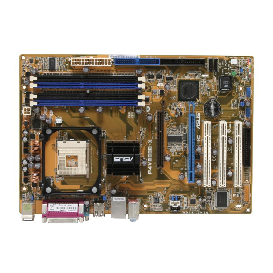
Page 16: Motherboard Overview
B: Keyboard KBPWR SPDIF1 CPU_FAN COM1 USB12 Bottom: Top: USB3 RJ-45 USB4 PT880 Ultra Top:Line In Center:Line Out Below:Mic In P4V800D-X 8201CL FP_AUDIO VT8237R+ PCIEX16 AD1888 ® PCI1 CR2032 3V SATA2 Lithium Cell CMOS Power SATA1 Super PCI2 SB_PWR PCI3... -
Page 17: Placement Direction
Place six screws into the holes indicated by circles to secure the motherboard to the chassis. Do not overtighten the screws! Doing so can damage the motherboard. Place this side towards-- the rear of the chassis P4V800D-X ® ASUS P4V800D-X Motherboard... -
Page 18: Central Processing Unit (Cpu)
Do not use processors with core speeds of less than 1GHz. P4V800D-X ® Gold Arrow P4V800D-X Socket 478 1.6.2 Installing the CPU Follow these steps to install a CPU: Locate the CPU socket. Open the socket by pulling the lever gently sideways away from the socket, then lift the lever upwards to a 90 to 100-degree angle. -
Page 19: System Memory
NOT force a DIMM into a socket to avoid damaging the DIMM. 4. For optimum compatibility, it is recommended that you obtain memory modules from qualified vendors. See the next page for a list of qualified DIMM vendors. 5. Visit ASUS website (www.asus.com) for latest Qualified Vendor List. ASUS P4V800D-X Motherboard... - Page 20 Qualified Vendors List Size Vendor Model Brand SS/DS Component 256MB Kingston KVR333X64C25/256 Kingston D3208DH1T-6 256MB Kingston KVR333X64C25/256 Hynix HY5DU56822BT-D43 512MB Kingston KVR333X64C25/512 Kingston D3208DH1T-6 512MB Kingston KVR400X64C3A/512 Hynix HY5DU56822BT-D43 512MB Kingston KVR400X64C3A/512 Kingston HY5DU12822BT-D43 256MB Kingston KVR400X64C3A/256 Hynix HY5DU56822BT-D43 256MB Kingston KVR400X64C3A/256 Kingston D3208DL3T-5A...
-
Page 21: Installing A Dimm
DIMM. Support the DIMM lightly with your fingers when pressing the retaining clips. The DIMM might get damaged when it flips out with extra force. Remove the DIMM from the socket. ASUS P4V800D-X Motherboard 1-11... -
Page 22: Expansion Slots
Expansion slots In the future, you may need to install expansion cards. The following sub-sections describe the slots and the expansion cards that they support. Make sure to unplug the power cord before adding or removing expansion cards. Failure to do so may cause you physical injury and damage motherboard components. -
Page 23: Standard Interrupt Assignments
When using PCI cards on shared slots, ensure that the drivers support “Share IRQ” or that the cards do not need IRQ assignments; otherwise, conflicts will arise between the two PCI groups, making the system unstable and the card inoperable. ASUS P4V800D-X Motherboard 1-13... -
Page 24: Agp Slot
P4V800D-X ® Keyed for 1.5v P4V800D-X Accelerated Graphics Port (AGP) 1.8.4 PCI slots The PCI slots support cards such as a LAN card, SCSI card, USB card, and other cards that comply with PCI specifications. The figure shows a LAN card installed on a PCI slot. -
Page 25: Jumpers
Please save all data before you exist. Except when clearing the RTC RAM, never remove the cap on CLRTC jumper default position. Removing the cap will cause system boot failure! CLRTC P4V800D-X ® Normal Clear CMOS (Default) P4V800D-X Clear RTC RAM ASUS P4V800D-X Motherboard 1-15... - Page 26 (Default) P4V800D-X USBPW2 ® +5VSB P4V800D-X USB device wake up (Default) • The USB device wake-up feature requires a power supply that can provide 500mA on the +5VSB lead for each USB port; otherwise, the system would not power up.
-
Page 27: Connectors
Serial connector. This 9-pin COM2 port is for pointing devices or other serial devices. 10. S/PDIF Coaxial out jack. This jack connects to external audio output devices with coaxial cable connectors. 11. PS/2 keyboard port (purple). This port is for a PS/2 keyboard. ASUS P4V800D-X Motherboard 1-17... -
Page 28: Internal Connectors
NOTE: Orient the red markings on the floppy ribbon cable to PIN 1. P4V800D-X Floppy disk drive connector IDE connectors (40-1 pin PRI_IDE, SEC_IDE) This connector is for an Ultra D M A 1 3 3 s i g n a l c a b l e . T h e U l t r a... - Page 29 Serial ATA connectors (7-pin SATA1, SATA2) These connectors are for the Serial ATA signal cables for Serial ATA hard disk drives. SATA2 P4V800D-X SATA1 ® P4V800D-X SATA connectors Important notes on Serial ATA ® ® ® • You must install Windows...
- Page 30 P4V800D-X ® USB56 USB78 P4V800D-X USB 2.0 connectors Never connect a 1394 cable to the USB connectors. Doing so will damage the motherboard! Internal audio connectors (4-pin CD, AUX) These connectors allow you to receive stereo audio input from sound sources such as a CD-ROM, TV tuner, or MPEG card.
- Page 31 MICPWR AGND MIC2 P4V800D-X Front Panel Audio Connector ATX power connectors (24-pin EATXPWR, 4-pin ATX12V) These connectors are for an ATX power supply. The plugs from the power supply are designed to fit these connectors in only one orientation. Find the proper orientation and push down firmly until the connectors completely fit.
- Page 32 The GAME/MIDI port connects a joystick or game pad for playing games, and MIDI devices for playing or editing audio files. P4V800D-X ® GAME P4V800D-X Game connector The GAME/MIDI port module isi purchased separately. 1-22 Chapter 1: Product Introduction...
- Page 33 IDE_LED ® PWRSW Requires an ATX power supply. P4V800D-X System Panel connector • System power LED (3-1 pin PLED) This connector is for the system power LED. Connect the chassis power LED cable to this connector. The system power LED lights up when you turn on the system power, and blinks when the system is in sleep mode.
-
Page 34: Chapter 2: Bios Setup
T h i s c h a p t e r t e l l s h o w t o c h a n g e the system settings through the BIOS Setup menus. Detailed descriptions of the BIOS parameters are also provided. BIOS Setup... -
Page 35: Managing And Updating Your Bios
(Updates the BIOS in DOS mode using a bootable floppy disk.) 2. ASUS EZ Flash (Updates the BIOS using a floppy disk during POST.) 3. ASUS CrashFree BIOS 2 - Updates the BIOS using a bootable floppy disk or the mother board support CD. -
Page 36: Using Afudos To Update The Bios
Write the BIOS filename on a piece of paper. You need to type the exact BIOS file name at the prompt. 2. Copy the AFUDOS.EXE utility from the support CD to the bootable floppy disk that contains the BIOS file. 3. Boot the system from the floppy disk. ASUS P4V800D-X Motherboard... - Page 37 4. At the DOS prompt, type the command line: afudos /i[filename.rom] where [filename.rom] means the latest (or original) BIOS file that you copied to the bootable floppy disk. 5. Press <Enter>. The screen displays the status of the update process. The BIOS information on the screen is for reference only.
-
Page 38: Using Asus Ez Flash To Update The Bios
If the correct BIOS file is not found in the floppy disk, the error message “P4V800D-X.ROM not found!” is displayed. 4. Insert the floppy disk that contains the BIOS file. If the P4V800D-X file is found in the floppy disk, EZ Flash performs the BIOS update process and automatically reboots the system when done. -
Page 39: Bios Setup Program
2.2 BIOS Setup Program The BIOS software is constantly being updated so the BIOS setup screens and descriptions in this section are for reference purposes only, and may not exactly match what you see on your screen. This motherboard supports a programmable Low Pin Count (LPC) chip that you can update using the provided utility described in section “2.1 Managing and updating your BIOS.”... -
Page 40: Bios Menu Screen
At the bottom right corner of a menu screen are the navigation keys for that particular menu. Use the navigation keys to select items in the menu and change the settings. Some of the navigation keys differ from one screen to another. ASUS P4V800D-X Motherboard... -
Page 41: Menu Items
2.2.4 Menu items The highlighted item on the menu bar displays the specific items for that menu. For example, selecting Main shows the Main menu items. The other items (Advanced, Power, Boot, and Exit) on the menu bar have their respective menu items. -
Page 42: Main Menu
[360K, 5.25 in.] [1.2M , 5.25 in.] [720K , 3.5 in.] [1.44M, 3.5 in.] [2.88M, 3.5 in.] 2.3.4 Legacy Diskette B [Disabled] Sets the type of floppy drive installed. Configuration options: [Disabled] [360K, 5.25 in.] [1.2M , 5.25 in.] [720K , 3.5 in.] [1.44M, 3.5 in.] [2.88M, 3.5 in.] ASUS P4V800D-X Motherboard... - Page 43 2.3.5 Primary/Secondary IDE Master/Slave While entering Setup, BIOS automatically detects the presence of IDE devices. There is a separate sub-menu for each IDE device. Select a device item then press <Enter> to display the IDE device information. Primary IDE Master Select the type of device connected Device...
-
Page 44: System Information
: 08.00.12 Build Date : 08/22/05 Processor Type : Intel(R) Pentium(R) 4 CPU 2.40GHz Speed : 2400MHz Count System Memory Size : 256MB AMI BIOS Displays the auto-detected BIOS information. System Memory Displays the auto-detected system memory. ASUS P4V800D-X Motherboard 2-11... -
Page 45: Advanced Menu
2.4 Advanced menu The Advanced menu items allow you to change the settings for the CPU and other system devices. Take caution when changing the settings of the Advanced menu items. Incorrect field values can cause the system to malfunction. Adjust system JumperFree Configuration frequency/voltage... -
Page 46: Usb Configuration
Allows you to enable or disable the port 64/60 emulation. Configuration options: [Disabled] [Enabled] When you use a USB mass storage device, a USB mass storage device configuration option will display. And this option is hiden if no USB mass storage detected. ASUS P4V800D-X Motherboard 2-13... -
Page 47: Cpu Configuration
2.4.3 CPU Configuration The items in this menu show the CPU-related information that the BIOS automatically detects. Configure advanced CPU settings This should be enabled in order to boot Manufacturer:Intel legacy OSes unable to Brand String:Intel(R)Pentium(R) 4 CPU 2.40GHz support CPUs with Frequency :2400MHz extended CPUID... -
Page 48: Chipset
Manual DRAM Frequency DRAM Timing [Maunel] Setting or AUTO by DRAM CAS# Latency [2.5] SPD. Precharge to Active(Trp) v02.58 (C)Copyright 1985-2004, American Megatrends, Inc. [5T] Active to Precharge(Tras) [20T] Active to CMD(Trcd) [5T] DRAM BUS Selection [Auto] ASUS P4V800D-X Motherboard 2-15... - Page 49 DRAM Frequency [Auto] Configuration options: [Auto] [200MHz] [266MHz] [333MHz] [400MHz] [533MHz] [666MHz] DRAM Timing [Manual] Configuration options: [Manual] [Auto] [Turbo] [Ultra] DRAM CAS# Latency [2.5] Configuration options: [1.5] [2.0] [2.5] [3.0] Precharge to Active(Trp) [5T] Configuration options: [2T] [3T] [4T] [5T] Active to Precharge(Tras) [20T] Configuration options: [5T] [6T] [7T] [8T] [9T] [10T] [11T] [12T] [13T] [14T] [15T] [16T] [17T] [18T] [19T] [20T]...
- Page 50 OnBoard LAN [Enabled] Allows you to enable or disable the onboard LAN controller. Configuration options: [Disabled] [Enabled] OnBoard LAN Boot ROM [Disabled] Allows you to enable or disable the onboard LAN Boot ROM. Configuration options: [Enabled] [Disabled] ASUS P4V800D-X Motherboard 2-17...
-
Page 51: Onboard Devices Configuration
2.4.5 Onboard Devices Configuration Allows BIOS to Select Configure Win627EHF Super IO Chipset Serial Port2 Base Addresses. Serial Port2 Address [2F8/IRQ3] Parallel Port Address [378] Parallel Port Mode [ECP] ECP Mode DMA Channel [DMA3] Parallel Port IRQ [IRQ7] Onboard Game/MIDI Port [Disabled] Select Screen ←→... -
Page 52: Pcipnp
Configuration options: [Disabled] [Enabled] IRQ xx [Available] When set to [Available], the specific IRQ is free for use of PCI/PnP devices. When set to [Reserved], the IRQ is reserved for legacy ISA devices. Configuration options: [PCI Device] [Reserved] ASUS P4V800D-X Motherboard 2-19... -
Page 53: Power Menu
2.5 Power menu The Power menu items allow you to change the power settings. Select an item then press <Enter> to display the configuration options. Select the ACPI state Suspend Mode [Auto] used for System Repost Video on S3 Resume [No] Suspend. -
Page 54: Apm Configuration
[Last State] Resume On Ring [Disabled] Allows you to enable or disable Resume On Ring. Configuration options: [Disabled] [Enabled] Resume On Lan [Disabled] Allows you to enable or disable the Resume On Lan. Configuration options: [Disabled] [Enabled] ASUS P4V800D-X Motherboard 2-21... - Page 55 Resume On PME# [Disabled] Allows you to enable or disable the Resume On PEM. Configuration options: [Disabled] [Enabled] Resume On KB [Disabled] Allows you to use specific keys on the keyboard to turn on the system. When set to [S5], the item Wake-up Key is enabled. This feature requires an ATX power supply that provides at least 1A on the +5VSB lead.
-
Page 56: Hardware Monitor
When using this type of CPU fan, you can not reduce the CPU fan speed even if you set the CPU Q-Fan Mode to [PWM]. VCORE Voltage, 3.3V Voltage, 5V Voltage, 12V Voltage The onboard hardware monitor automatically detects the voltage output through the onboard voltage regulators. ASUS P4V800D-X Motherboard 2-23... -
Page 57: Boot Menu
1st Boot Device [1st FLOPPY DRIVE] 2nd Boot Device [HDD:PM-ST340014A] A device enclosed in 3rd Boot Device [CDROM:SM-ASUS CD-S] parenthesis has been disabled in the corresponding type menu. 1st ~ xxth Boot Device [1st FLOPPY DRIVE] These items specify the boot device priority sequence from the available devices. -
Page 58: Boot Settings Configuration
Allows you to enable or disable the full screen logo display feature. Configuration options: [Disabled] [Enabled] Set this item to [Enabled] to use the ASUS MyLogo™ feature. AddOn ROM Display Mode [Force BIOS] Sets the display mode for option ROM. -
Page 59: Security
Hit ʻDELʼ Message Display [Enabled] When set to [Enabled], the system displays the message “Press DEL to run Setup” during POST. Configuration options: [Disabled] [Enabled] Interrupt 19 Capture [Disabled] When set to [Enabled], this function allows the option ROMs to trap Interrupt 19. Configuration options: [Disabled] [Enabled] 2.6.3 Security The Security menu items allow you to change the system security settings. - Page 60 Password Check [Setup] When set to [Setup], BIOS checks for user password when accessing the Setup utility. When set to [Always], BIOS checks for user password both when accessing Setup and booting the system. Configuration options: [Setup] [Always] ASUS P4V800D-X Motherboard 2-27...
-
Page 61: Exit Menu
2.7 Exit menu The Exit menu items allow you to load the optimal or failsafe default values for the BIOS items, and save or discard your changes to the BIOS items. Exit Options Exit system setup after saving the Exit & Save Changes changes. - Page 62 This chapter describes the contents of the support CD that comes with the motherboard package. Software Support...
-
Page 63: Installing An Operating System
The contents of the support CD are subject to change at any time without notice. Visit the ASUS website(www.asus.com) for updates. 3.2.1 Running the support CD Place the support CD to the optical drive. The CD automatically displays the Drivers menu if Autorun is enabled in your computer. -
Page 64: Drivers Menu
The Utilities menu shows the applications and other software that the motherboard supports. ASUS PC Probe This smart utility monitors the fan speed, CPU temperature, and system voltages, and alerts you of any detected problems. This utility helps you keep your computer in healthy operating condition. ASUS P4V800D-X Motherboard... -
Page 65: Contacts Menu
Please install first Adobe Acrobat,then open Raid Userʼs Manual. 3.2.4 Contacts menu Click the Contact tab to display the ASUS contact information. You can also find this information on the inside front cover of this user guide. Chapter 3: Software Support... -
Page 66: Via Raid Configurations
Installing Serial ATA (SATA) hard disks To install the SATA hard disks for a RAID configuration: Install the SATA hard disks into the drive bays. Connect the SATA signal cables. Connect a SATA power cable to the power connector on each drive. ASUS P4V800D-X Motherboard... -
Page 67: Via Raid Configurations
3.3.2 VIA RAID configurations The motherboard includes a high performance IDE RAID controller integrated in the VIA VT8237R PLUS southbridge chipset. It supports RAID 0 and RAID 1 with two independent Serial ATA channels. Setting the BIOS RAID items After installing the hard disk drives, make sure to set the necessary RAID items in the BIOS before setting your RAID configuration. -
Page 68: Raid 0 For Performance
The following confirmation message appears: The data on the selected disks will be destroyed. Continue? (Y/N) Press <Y> to confirm or <N> to return to the configuration options. Press <Esc> to go back to main menu. ASUS P4V800D-X Motherboard... -
Page 69: Raid 1 For Data Protection
RAID 1 for data protection From the create array menu, select Array Mode, then press <Enter>. The supported RAID configurations appear on a pop-up menu. RAID 0 for performance RAID 1 for data protection RAID 1 for data protection RAID SPAN for capacity Select RAID 1 for data protection then press <Enter>. -
Page 70: Creating A Raid Driver Disk
During the OS installation, the system prompts you to press the F6 key to install third-party SCSI or RAID driver. Press <F6> then insert the floppy disk with RAID driver into the floppy disk drive. Follow the succeeding screen instructions to complete the installation. ASUS P4V800D-X Motherboard...
Need help?
Do you have a question about the P4V800D-X and is the answer not in the manual?
Questions and answers