Table of Contents
Advertisement
CONSUMER SERVICES TECHNICAL
EDUCATION GROUP PRESENTS
REFRIGERA
REFRIGERA T T T T T OR/ FREEZERS
REFRIGERA
REFRIGERA
REFRIGERA
KSBS20QEWH0
KSBS20QEWH0
KSBS20QEWH0
KSBS20QEWH0
KSBS20QEWH0
KSBS20QEAL0
KSBS20QEAL0
KSBS20QEAL0
KSBS20QEAL0
KSBS20QEAL0
KSBS20QEBL0
KSBS20QEBL0
KSBS20QEBL0
KSBS20QEBL0
KSBS20QEBL0
KSFS20QEWH0
KSFS20QEWH0
KSFS20QEWH0
KSFS20QEWH0
KSFS20QEWH0
KSFS20QEAL0
KSFS20QEAL0
KSFS20QEAL0
KSFS20QEAL0
KSFS20QEAL0
KSFS20QEBL0
KSFS20QEBL0
KSFS20QEBL0
KSFS20QEBL0
KSFS20QEBL0
26" DEEP
26" DEEP
26" DEEP
26" DEEP
26" DEEP
SIDE - BY SIDE
SIDE - BY SIDE
SIDE - BY SIDE
SIDE - BY SIDE
SIDE - BY SIDE
OR/ FREEZERS
OR/ FREEZERS
OR/ FREEZERS
OR/ FREEZERS
MODELS
MODELS
MODELS
MODELS
MODELS
i
R - 8 4
ED20DBXEW00
ED20DBXEW00
ED20DBXEW00
ED20DBXEW00
ED20DBXEW00
ED20DBXEN00
ED20DBXEN00
ED20DBXEN00
ED20DBXEN00
ED20DBXEN00
ED20DBXEB00
ED20DBXEB00
ED20DBXEB00
ED20DBXEB00
ED20DBXEB00
ED20DFXEW00
ED20DFXEW00
ED20DFXEW00
ED20DFXEW00
ED20DFXEW00
ED20DFXEN00
ED20DFXEN00
ED20DFXEN00
ED20DFXEN00
ED20DFXEN00
ED20DFXEB00
ED20DFXEB00
ED20DFXEB00
ED20DFXEB00
ED20DFXEB00
JOB AID
Part No. 4321940
Advertisement
Table of Contents
Troubleshooting

Related Manuals for Whirlpool KSBS20QEWH0


Summary of Contents for Whirlpool KSBS20QEWH0
- Page 1 REFRIGERA REFRIGERA REFRIGERA T T T T T OR/ FREEZERS OR/ FREEZERS OR/ FREEZERS OR/ FREEZERS REFRIGERA REFRIGERA OR/ FREEZERS MODELS MODELS MODELS MODELS MODELS KSBS20QEWH0 KSBS20QEWH0 KSBS20QEWH0 ED20DBXEW00 ED20DBXEW00 ED20DBXEW00 KSBS20QEWH0 KSBS20QEWH0 ED20DBXEW00 ED20DBXEW00 KSBS20QEAL0 KSBS20QEAL0 KSBS20QEAL0 KSBS20QEAL0 KSBS20QEAL0...
-
Page 2: Introduction
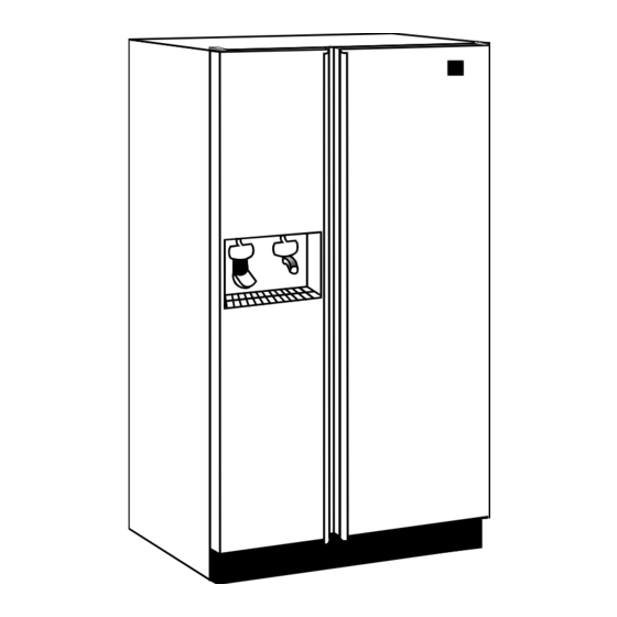
26" deep cabinets. 26" DEEP SIDE-BY-SIDE REFRIGERATOR/FREEZERS has been compiled to provide the most recent information on design, features, troubleshooting, service and repair procedures. Whirlpool required sweep charge procedures are to be strictly adhered to when repairing the sealed system. -
Page 3: Table Of Contents
TABLE OF CONTENTS INTRODUCTION ........................ii TABLE OF CONTENTS ...................... iii SECTION ONE FEATURES AND DESIGN FEATURES AND DESIGN FEATURES AND DESIGN FEATURES AND DESIGN FEATURES AND DESIGN ..............................................1 1 1 1 1 Safety ..........................1 R134a Service Information ..................... -
Page 5: Features And Design Features And Design
View Section 1 of the Video Tape SECTION 1 GENERAL INFORMATION GENERAL INFORMATION GENERAL INFORMATION GENERAL INFORMATION GENERAL INFORMATION SAFETY WARNING To avoid the risk of electrical shock, property damage, personal injury or death: • The power cord must be plugged into a 3-prong grounding-type wall receptacle, grounded in accordance with the National Electrical Code, ANSI/NFPA 70 - latest edition and local codes and ordinances. -
Page 6: R134A Service Information
R134a REFRIGERANT SERVICE INFORMATION This product uses R134a refrigerant. This refrigerant requires synthetic Ester Oil in the compressor. This cooling system does not tolerate contamination from any of the following: • Other Refrigerants • Moisture • Petroleum-based Lubricants • Silicone Lubricants •... -
Page 7: Installation Considerations
View Section 2 of the Video Tape SECTION 2 GENERAL INFORMATION GENERAL INFORMATION GENERAL INFORMATION GENERAL INFORMATION GENERAL INFORMATION INSTALLATION CONSIDERATIONS LEVELING THE UNIT AND ALIGNING THE DOORS Top Hinge Locations Rear Roller Fig. 1 Adjustment Screw Toe Grille Front Roller Location Adjustment Screw... - Page 8 ALIGNMENT AND LEVELING PROCEDURES FLOW CHART Slide Unit into Final Location. Unit Stable? 1. Remove toe grille by 1. Remove toe grille by pulling forward at pulling forward at each end. each end. 2. Turn roller adjust- 2. Turn roller adjust- ment screw(s) clock- ment screw for the wise until unit is...
-
Page 9: Theory Of Operation Theory Of Operation
View Section 3 of the Video Tape SECTION 3 THEORY OF OPERATION THEORY OF OPERATION THEORY OF OPERATION THEORY OF OPERATION THEORY OF OPERATION TEMPERATURE CONTROLLED MEAT LOCKER The 26" deep side-by-side refrigerator/freezer is equipped with a chilled meat locker which will keep the contents of the drawer approximately 5°F colder than the rest of the refrigerator section. -
Page 10: Auger Motor
AUGER MOTOR AUGER MOTOR ASSEMBLY DRIVER LOCKING NUT CAPACITOR AUGER MOTOR SUPPORT AUGER MOTOR COVER Fig. 7 ICE BUCKET ICE BUCKET ASSEMBLY HELIX CAP CRUSHED ICE LIFT ICE AGITATOR WHEEL CRUSHED ICE BAR STEPPED WASHER ROTATING BLADE WAVED WASHERS STATIC BLADE ICE DAMPER STEPPED WASHER STATIC BLADE... - Page 11 6. Dispense ice by holding glass against ice lever arm. The mechanically operated ice chute door opens, and the motor driven helix is energized and ice is automatically dispensed into glass. When glass is withdrawn, a delay mechanism slowly closes the ice chute door. WARNING To avoid risk of personal Injury or property damage, refrigerator must be unplugged and ice storage bin must be removed before attempting to service...
- Page 12 6. If odor, taste and sediment are a problem, a granulated activated carbon filter should be installed on the household plumbing line. 7. Underneath the ice and water dispenser is a small sump to catch any spillage that may occur. This is not a drain.
-
Page 13: Temperature Control Operation
TEMPERATURE CONTROL OPERATION 1. Freezer temperature is regulated by an air sensing thermostat located at the top rear of the refrigerator compartment. A sensing tube goes into a well which routes the tube into the freezer section. This thermostat actuates the compressor to circulate refrigerant through the sealed system. -
Page 14: Adaptive Defrost Function
2. Refrigerator temperature is regulated by an air damper control. This control governs the amount of refrigerated air entering the refrigerator compartment. (Fig. 11) The control should be set to maintain 28°F to 40°F fresh food temperature. Air Supply to Freezer Back Refrigerator (Air Baffle) -
Page 15: Adaptive Defrost Operation
ADAPTIVE DEFROST OPERATION 1. This unit is equipped with Adaptive Defrost Control (ADC). (Fig. 12) A defrost cycle occurs after a predetermined length of compressor run time. The length of accumulated compressor run time is determined by a microprocessor that monitors the length of a defrost cycle (the time) interval between energizing the defrost heater and the defrost thermostat opening). - Page 16 4. Vacation Mode Defrost Interval Interruption: The Vacation Mode Defrost Interval will be interrupted when either the freezer or refrigerator door is opened. • The next defrost cycle will occur 8 hours after the door is opened and the ADC will revert to CRTD (1) = 8 hours.
-
Page 17: Component Access Component Access
COMPONENT ACCESS COMPONENT ACCESS Accessing the components in the 26" Deep Side-by-Side Refrigerator/Freezer is generally quite similar to other typical Whirlpool units. COMPONENT COMPARTMENT Components located in the component compartment are assembled on a slide out tray at the bottom of the unit. -
Page 18: Freezer Section
Accessing the Heat Exchanger and Wiring Harness The heat exchanger, water supply tube to the automatic ice maker and wiring harness are located under two (2) metal heat exchanger covers on the back of the cabinet. 1. Remove the seven (7) hex-head screws securing the component compartment cover to the cabinet. - Page 19 NOTE: When replacing the motor box be sure the wiring harness routes through the box correctly. Portions of the harness are covered with a plastic sheath that allows the wiring to pass into and out of the box at the top (down from the automatic ice maker) and right side (to the light fixture.) Replacement: 1.
-
Page 20: Removing The Evaporator Fan Motor
Removing the Evaporator Fan Motor EVAPORATOR FAN SHROUD The evaporator fan motor is mounted on a bracket that is attached to a shroud mounted to the back wall of the freezer section. (Fig. 18) Fig. 18 1. Removing the two (2) hex-head screws that secure the fan motor bracket to the shroud. -
Page 21: Refrigerator Section
Refrigerator Section The thermostat, air ducts and drinking water reservoir are all accessible from inside the refrigerator section. Removing the Drinking Water Reservoir The drinking water reservoir (Fig. 21) is located at the bottom of the refrigerator section. NOTE: The bottom shelf and vegetable crispers must be removed. - Page 22 COLD AIR Removing Cold Air Damper DUCT 1. Remove the control cover. 2. Remove the two (2) phillips-head screws securing the cold air damper to the duct work. (Fig. 24) 3. Remove the cold air damper from the unit. Fig. 24 DAMPER ASSEMBLY ICE AND WATER DISPENSING UNIT...
- Page 23 Fig. 29 Fig. 28 FLUSH LOOK MODELS Factory Installed Flush Look Trim Package CUT OUT FOR HINGE DOOR COVER A FLUSH LOOK (BUILT-IN) model can be purchased with factory TRIM installed perimeter molding around the doors. This molding extends beyond the top of the door to hide the top hinges and is designed to accommodate custom panels for both the refrigerator and freezer Fig.
-
Page 24: Section Four
Section Four CONFIRMATION OF LEARNING CONFIRMATION OF LEARNING CONFIRMATION OF LEARNING CONFIRMATION OF LEARNING CONFIRMATION OF LEARNING EXERCISES EXERCISES EXERCISES EXERCISES EXERCISES... -
Page 25: Diagnosis And Troubleshooting
View Section 5 of the Video Tape SECTION 5 TROUBLESHOOTING AND DIAGNOSTICS TROUBLESHOOTING AND DIAGNOSTICS TROUBLESHOOTING AND DIAGNOSTICS TROUBLESHOOTING AND DIAGNOSTICS TROUBLESHOOTING AND DIAGNOSTICS TROUBLESHOOTING GUIDE POSSIBLE CAUSE PROBLEM Operating Sound Level A. See Owners manual for explanation of normal operating sounds. Freezer Warm - Compressor Off A. -
Page 26: Troubleshooting
TROUBLESHOOTING POSSIBLE CAUSE PROBLEM Long off Cycle - Too Warm at Start A. Low ambient temperature B. Freezer temperature control knob set too warm. C. Freezer temperature control out of calibration Short off Cycle A. High ambient and/or heavy usage B. -
Page 27: Dignostic Tests
DIAGNOSTIC TESTS See the Tech Sheet for test procedures on electrical and mechanical components not listed here. COMPONENT TEST SOLUTION Adaptive Defrost Control Input Voltage Readings and Checks L1 to L2 - Line voltage should be present whenever the unit is powered. - Page 28 CONFIRMATION OF LEARNING EXERCISES CONFIRMATION OF LEARNING EXERCISES CONFIRMATION OF LEARNING EXERCISES CONFIRMATION OF LEARNING EXERCISES CONFIRMATION OF LEARNING EXERCISES...
-
Page 29: Tech Tips Tech Tips
View Section 6 of the Video Tape SECTION 6 TECH TIPS TECH TIPS TECH TIPS TECH TIPS TECH TIPS TYPICAL EXTERNAL SWEAT PATTERNS LEFT FRONT RIGHT BACK CLASSIFICATION OF CONDENSATION 1 = Haze or Fog 2 = Beading 3 = Beads or Small BOTTOM Drops 4 = Drops Running... -
Page 30: Wiring Diagram
WIRING DIAGRAM... -
Page 31: Strip Circuits
STRIP CIRCUITS AUTOMATIC DEFROST CONTROL ENERGIZING CIRCUIT COMPRESSOR RUN CIRCUIT EVAPORATOR FAN CIRCUIT DEFROST CIRCUIT... - Page 32 DEFROST RUN TIME MONITOR CIRCUIT REFRIGERATOR AND FREEZER LIGHT MONITOR CIRCUIT ICE & WATER DISPENSER AND AUTOMATIC ICE MAKER CIRCUIT...
-
Page 33: Model Number Designation
SERIAL AND MODEL NUMBER DESIGNATORS The serial number for all Whirlpool and KitchenAid brand refrigerator/freezers contain the following designations: EC E 39 40174 Manufacturer Site/Source Calendar Year Calendar Week Sequential Serial Number The model number for the KitchenAid brand 26" deep freestanding and flush look side-by-side refrig-... - Page 34 The model number for the Whirlpool brand 26" deep freestanding and flush look side-by-side refrig- erator/freezers contain the following designations: Model Number Marketing Channel (if present) Product Group E = Refrigeration Product Identification Capacity Model Series D = DesignerStyle Feature Code...
- Page 35 ANSWER SHEET CONFIRMATION OF LEARNING CONFIRMATION OF LEARNING CONFIRMATION OF LEARNING CONFIRMATION OF LEARNING CONFIRMATION OF LEARNING EXERCISES EXERCISES EXERCISES EXERCISES EXERCISES...