Extron electronics XPA 1002 User Manual
Xtra series half-rack audio power amplifiers
Hide thumbs
Also See for XPA 1002:
- User manual (31 pages) ,
- Setup manual (2 pages) ,
- Specifications (2 pages)
Table of Contents
Advertisement
Quick Links
Download this manual
See also:
Setup Manual
Advertisement
Table of Contents

Related Manuals for Extron electronics XPA 1002


Summary of Contents for Extron electronics XPA 1002
- Page 1 User Guide Audio Products XTRA Series ™ Half-Rack Audio Power Amplifiers 68-2354-01 Rev. A 02 14...
-
Page 2: Safety Instructions
Safety Instructions Safety Instructions • English Инструкция по технике безопасности • Русский WARNING: This symbol, , when used on the product, is intended to ПРЕДУПРЕЖДЕНИЕ: Данный символ, , если указан на продукте, alert the user of the presence of uninsulated dangerous voltage within the предупреждает... -
Page 3: Conventions Used In This Guide
FCC Class B Notice This equipment has been tested and found to comply with the limits for a Class B digital device, pursuant to part 15 of the FCC rules. These limits provide reasonable protection against harmful interference in a residential installation. This equipment generates, uses, and can radiate radio frequency energy and, if not installed and used in accordance with the instructions, may cause harmful interference to radio communications. -
Page 5: Table Of Contents
Contents Introduction ..........Operation ............About this Manual..........1 Front Panel Features and Operation ....9 Terms Used in this Manual ......1 Rear Panel Features and Operation ....11 Features ............1 Remote Volume Control ......17 Controlling Multiple Amplifiers with One Volume Controller ........ -
Page 7: Introduction
Terms Used in this Manual The terms “amplifier” and “power amplifier” are used interchangeably in this manual to refer to all of the XPA models. “XPA 1002” refers to the 1002 and the 1002 Plus. ”XPA 2001” refers to both the XPA 2001-70V and the XPA 2001-100V. - Page 8 2001 series to be remotely controlled using the optional Extron VCM 100 Series volume and mute or VC 50 volume controllers. Bridgeable outputs — The power output of the XPA 1002 and XPA 1002 Plus can be effectively doubled by bridging the output. A mono source is wired to both the left and right input while the output is wired for bridged operation.
-
Page 9: Installation
Installation and service must be performed by authorized personnel only (see UL Guidelines for Rack Mounting on page 4). Application Examples The following illustrations are application examples for the XPA 1002 series and the XPA 2001 series. U TS M OT... -
Page 10: Mounting The Xtra Series Amplifiers
XPA 2001 Series Application Example Figure 2. Mounting the XTRA Series Amplifiers The XPA 1002 series and XPA 2001 series of audio amplifiers can be set on a table, mounted on a rack shelf, or mounted in the plenum space above a ceiling-mounted projector. -
Page 11: Rack Mounting
(such as the use of power strips). Rack Mounting The XPA 1002 series and XPA 2001 series can be mounted in a rack shelf using the optional RSU 129 1U Universal rack shelf or the 1U Basic rack shelf, as follows. -
Page 12: Flexible Conduit Adapter Kit Installation
Rack Mounting Ventilation Recommendations Excessive heat can decrease the optimal lifetime of the power amplifier. An over temp indicator LED on the front panel of the amplifier lights red whenever the recommended Front Panel Features and Operation operating temperature has been exceeded (see on page 9). -
Page 13: Installing The Flexible Conduit Kit
UL Requirements The UL requirements listed below pertain to the installation of the flexible conduit onto a XPA 1002 or XPA 2001. • This unit is not to be used beyond its rated voltage range. - Page 14 Remove the 2 screws holding the hot (Line) and neutral wires from the terminal block on the PCB (see figure 6). Blue Wire Brown Wire Remove nut Remove screws (both sides) to release IEC connector plate. Figure 6. Removing the IEC Connector Remove the ground wire nut from the grounding stud on the bottom of the enclosure, as shown above.
-
Page 15: Operation
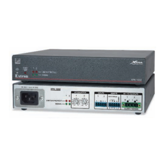
• • Rear Panel Features and Operation Front Panel Features and Operation OVER TEMP LIMITER/PROTECT SIGNAL XPA 1002 XPA 1002 XPA 1002 Plus Front Panel OVER TEMP LIMITER/PROTECT SIGNAL XPA 2001 XPA 2001-70V XPA 2001-100V Front Panel Power indicator LED — This LED lights: •... - Page 16 Limiter/Protect indicator LEDs — These LEDs (representing their respective output channels) light red under three circumstances: LIMITER/PROTECT • When the output wiring is shorted together. When audio clipping occurs, the LED of the corresponding channel blinks once • per clip occurrence. When the amplifier overheats, both LEDs are lit.
-
Page 17: Rear Panel Features And Operation
XPA 1002 100-240V 0.5A, 50-60Hz ATTENUATION INPUTS REMOTE 8 / 4 OUTPUTS 50mA LIMITER/PROTECT SIGNAL ∞ ∞ XPA 1002 XPA 1002 Plus Rear Panel XPA 2001-70V 100-240V 0.5A, 50-60Hz ATTENUATION INPUTS REMOTE 70 V OUTPUT 50mA (SUMMED) LIMITER/PROTECT 80 Hz SIGNAL ∞... - Page 18 à Balanced or unbalanced stereo or mono audio input connector (XPA 1002 series) — Wire the 3.5 mm 5-pin captive screw connector for balanced or unbalanced input as show in the diagram on the following page. NOTE: The power output of the XPA 1002 series amplifiers can be effectively doubled by bridging the output.
- Page 19 Ring Sleeve Sleeves Ring Sleeve Sleeve Sleeve Ring Unbalanced Stereo Input Balanced Stereo Input Unbalanced Mono Input Balanced Mono Input Do not tin the wires! INPUTS INPUTS NOTE: The input connector receptacle may be labeled one of two ways. The wiring and function are the same, whichever way your product is labeled.
- Page 20 50 mA REMOTE VOL/MUTE 50mA STANDBY 2K OHMS MUTE 10K OHMS MUTE SWITCH VOLUME Pin 5 (standby) connected to ground (pin 4) places the amplifier in standby mode. Standby mode turns off all output, although the amplifier is still receiving power. Use the included 2-pin, 3.5 mm captive screw connector to remotely ground pin 5.
- Page 21 Doing so will short the outputs, damage the amplifier, or both. NOTE: The power output of the XPA 1002 series can be effectively doubled by bridging the output. A mono source is wired to both the left and right input while the output is wired for bridged operation.
- Page 22 ç Mono audio output connector — Wire the included 2-pole, 5 mm screw lock captive screw connector for mono audio (see the steps below). Output is designed to power 70 V (XPA 2001-70V) or 100 V (XPA 2001-100V) line distribution systems and is rated at 200 watts.
-
Page 23: Remote Volume Control
High pass filter (HPF) toggle switch (XPA 2001 series) — Use a small screwdriver to toggle this recessed two-position switch. Setting the switch to 80 Hz (default) prevents the saturation of 70 V and 100 V speaker input transformers by low frequency signals. -
Page 24: Controlling Multiple Amplifiers With One Volume Controller
Controlling Multiple Amplifiers with One Volume Controller Several XPA 1002 and XPA 2001 series units can be daisy-chained so that one volume controller can simultaneously regulate the volume of all the amplifiers. NOTES: • As additional amplifiers are added to the daisy chain, the sensitivity of the volume potentiometer will change. -
Page 25: Bridged Mono Output
Bridged Mono Output The power output of the XPA 1002 and XPA 1002 Plus can be effectively doubled by bridging the output. Bridging allows power to be output in mono at 200 watts at 8 ohms. ATTENTION: Failure to follow these instructions may result in damage to the unit. -
Page 26: Troubleshooting
Troubleshooting The front and rear panels have LED warning indicators, as described in the following diagnostic information. Amplifier Fails to Exit Standby Mode Promptly The input channel (channels 1 and 2) Signal LED lights green per indicated input channel when an input signal is detected. Power LED Signal LED Problem Description... -
Page 27: Amplifier Enters Standby Mode Too Early
Amplifier Enters Standby Mode Too Early The input channel (channels 1 and 2) Signal LED lights green per indicated input channel when an input signal is detected. Power LED Signal LED Problem Description Problem Solution Color State Green or Enters standby mode The output signal level of the Amber intermittently... -
Page 28: Extron Warranty
Extron Warranty Extron Electronics warrants this product against defects in materials and workmanship for a period of three years from the date of purchase. In the event of malfunction during the warranty period attributable directly to faulty workmanship and/or materials, Extron Electronics will, at its option, repair or replace said products or components, to whatever extent it shall deem necessary to restore said product to proper operating condition, provided that it is returned within the warranty period, with proof of purchase and description of malfunction to: USA, Canada, South America,...
Need help?
Do you have a question about the XPA 1002 and is the answer not in the manual?
Questions and answers