Table of Contents
Advertisement
Quick Links
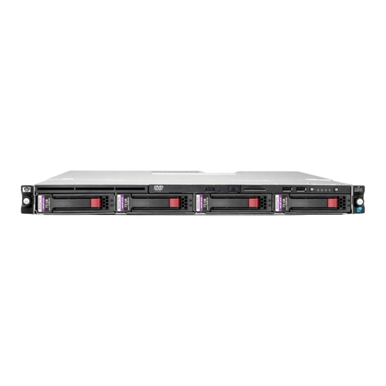
HP ProLiant DL120 G7 Server
User Guide
Abstract
This document is for the person who installs, administers, and troubleshoots servers and storage systems. This document is intended for experienced
IT professionals or end-users with no or prior hardware setup experience. HP assumes you are qualified in the servicing of computer equipment and
trained in recognizing hazards in products with hazardous energy levels.
Part Number: 638025-003
September 2012
Edition: 3
Advertisement
Table of Contents
Troubleshooting

Related Manuals for HP ProLiant DL120 G7


Summary of Contents for HP ProLiant DL120 G7
-
Page 1: User Guide
This document is for the person who installs, administers, and troubleshoots servers and storage systems. This document is intended for experienced IT professionals or end-users with no or prior hardware setup experience. HP assumes you are qualified in the servicing of computer equipment and trained in recognizing hazards in products with hazardous energy levels. - Page 2 © Copyright 2011, 2012 Hewlett-Packard Development Company, L.P. The information contained herein is subject to change without notice. The only warranties for HP products and services are set forth in the express warranty statements accompanying such products and services. Nothing herein should be construed as constituting an additional warranty. HP shall not be liable for technical or editorial errors or omissions contained herein.
-
Page 3: Table Of Contents
Contents Component identification ....................... 7 Front panel components ..........................7 Front panel LEDs ............................8 Rear panel components ..........................8 Rear panel LEDs ............................9 PCIe expansion slot definitions ........................10 System board components ........................10 System board LEDs ........................11 System maintenance switch ...................... - Page 4 Storage controller option .......................... 37 BBWC module and battery pack option ..................... 38 Redundant hot-plug power supply option (with cage) ................... 40 HP Trusted Platform Module option ......................44 Installing the Trusted Platform Module board ..................45 Retaining the recovery key/password ....................46 Enabling the Trusted Platform Module ....................
- Page 5 Version control ..........................61 ProLiant Support Packs ........................62 Operating System Version Support ....................62 Firmware ............................62 HP Smart Update Manager ......................62 Change control and proactive notification ..................63 Care Pack ............................ 63 Troubleshooting .......................... 64 Pre-diagnostic steps ..........................64 Important safety information ......................
- Page 6 Power supply specifications ........................89 Support and other resources ......................91 Before you contact HP ..........................91 HP contact information ..........................91 Customer Self Repair ..........................91 Acronyms and abbreviations ......................99 Documentation feedback ......................102 Index ............................103 Contents 6...
-
Page 7: Component Identification
Component identification Front panel components • SFF model Item Description Optical drive Serial label pull tab USB connectors (2) Drive bays • LFF model Item Description Optical drive Serial label pull tab USB connectors (2) Drive bays Component identification 7... -
Page 8: Front Panel Leds
Front panel LEDs Item Description Status Internal health LED Green = Normal Amber = System degraded Red = System critical Off = Normal (when in standby mode) NIC 1 link/activity LED Green = Network link Flashing green = Network link and activity Off = No network link If the power is off, view the LEDs on the RJ-45 connector. -
Page 9: Rear Panel Leds
Item Description 10/100/1000 NIC 1 connector/ shared iLO management port HP dedicated iLO management port (optional) USB connectors (4) T10/T15 tool Slot 1 PCIe2 x16 (16, 8, 4, 1) Slot 2 PCIe2 x8 (4, 1) Rear panel LEDs Item Description... -
Page 10: Pcie Expansion Slot Definitions
PCIe expansion slot definitions Slot Type Length Connector Interconnect PCIe2 Full PCIe2 Half System board components Item Description DIMM slots 1-4 Processor socket System power connector (24 pin) Fan connector 7 (Reserved) Fan connector 8 (Reserved) Fan connector 3 Fan connector 4 RPS connector Fan connector 5 System battery... -
Page 11: System Board Leds
Item Description TPM connector Power supply connector (4 pin) System maintenance switch HP dedicated iLO management connector System board LEDs Item LED description Status Power supply 1 Red = Power supply 1 failed failure Off = Normal Power supply 2... -
Page 12: Nmi Functionality
The administrator must use the iLO Virtual NMI feature to force the OS to invoke the NMI handler and generate a crash dump log. For additional information, see the HP website (http://h20000.www2.hp.com/bc/docs/support/SupportManual/c00797875/c00797875.pdf). DIMM slot locations DIMM slots are numbered sequentially for the processor. -
Page 13: Sas And Sata Device Numbering
• 2 DIMMs: 2A+4B • 3 DIMMs: 2A+4B+1C • 4 DIMMs: All DIMMs SAS and SATA device numbering • LFF device bay numbering • SFF device bay numbering SAS and SATA drive LEDs Item Description Fault/UID LED (amber/blue) Online LED (green) Component identification 13... -
Page 14: Bbwc Module Leds
A fully-charged battery can normally preserve data for at least two days. The battery lifetime also depends on the cache module size. For more information, see the controller QuickSpecs on the HP website (http://www.hp.com). Double flash, then The cache microcontroller is waiting for the host controller to —... -
Page 15: Fan Locations
LED3 pattern LED4 pattern Interpretation One flash per The battery pack is below the minimum charge level and is being — second charged. Features that require a battery (such as write cache, capacity expansion, stripe size migration, and RAID migration) are temporarily unavailable until charging is complete. -
Page 16: T-10/T15 Torx Screwdriver
T-10/T15 Torx screwdriver The server includes a T-10/T-15 Torx screwdriver located on the rear panel of the server. Use the screwdriver to loosen screws during hardware configuration procedures. Component identification 16... -
Page 17: Operations
Operations Power up the server Connect each power cord to the server. Connect each power cord to the power source. Press the Power On/Standby button. The server exits standby mode and applies full power to the system. The system power LED changes from amber to green. -
Page 18: Remove The Access Panel
To remove the server from an HP, Compaq branded, TELCO, or third-party rack: Power down the server (on page 17). Disconnect all peripheral cables and power cords from the server rear panel. Loosen the thumbscrews that secure the server faceplate to the front of the rack. -
Page 19: Install The Pcie Riser Cage
Remove the riser cage. Install the PCIe riser cage CAUTION: To prevent damage to the server or expansion boards, power down the server and remove all AC power cords before removing or installing the PCIe riser board assembly. Install the PCIe riser cage. Connect any internal cables for expansion boards. -
Page 20: Install The Air Baffle
CAUTION: For proper cooling, do not operate the server without the access panel, baffles, expansion slot covers, or blanks installed. If the server supports hot-plug components, minimize the amount of time the access panel is open. Power down the server (on page 17). Remove the access panel (on page 18). - Page 21 Install the access panel (on page 18). Power up the server (on page 17). Operations 21...
-
Page 22: Setup
For more information on HP Care Pack Services, see the HP website (http://www.hp.com/services/carepack). Rack planning resources The rack resource kit ships with all HP branded or Compaq branded 9000, 10000, and H9 series racks. For more information on the content of each resource, see the rack resource kit documentation. Optimum environment When installing the server in a rack, select a location that meets the environmental standards described in this section. -
Page 23: Space And Airflow Requirements
HP servers draw in cool air through the front door and expel warm air through the rear door. Therefore, the front and rear rack doors must be adequately ventilated to allow ambient room air to enter the cabinet, and the rear door must be adequately ventilated to allow the warm air to escape from the cabinet. -
Page 24: Power Requirements
Because of the high ground-leakage currents associated with multiple servers connected to the same power source, HP recommends the use of a PDU that is either permanently wired to the building’s branch circuit or includes a nondetachable cord that is wired to an industrial-style plug. NEMA locking-style plugs or those complying with IEC 60309 are considered suitable for this purpose. -
Page 25: Identifying The Contents Of The Server Shipping Carton
WARNING: To reduce the risk of personal injury or damage to the equipment, be sure that: • The leveling jacks are extended to the floor. The full weight of the rack rests on the leveling jacks. • The stabilizing feet are attached to the rack if it is a single-rack installation. •... -
Page 26: Powering Up And Configuring The Server
Press the F9 key when prompted during the boot process to change the server settings using RBSU. The system is set up by default for the English language. For more information on the automatic configuration, refer to the HP ROM-Based Setup Utility User Guide located on the Documentation CD. -
Page 27: Registering The Server
Registering the server To register the server, refer to the HP Registration website (http://register.hp.com). Setup 27... -
Page 28: Hardware Options Installation
Hardware options installation Introduction If more than one option is being installed, read the installation instructions for all the hardware options and identify similar steps to streamline the installation process. WARNING: To reduce the risk of personal injury from hot surfaces, allow the drives and the internal system components to cool before touching them. -
Page 29: Dimm Identification
R = RDIMM (registered) E = UDIMM (unbuffered with ECC) For the latest supported memory information, see the QuickSpecs on the HP website (http://www.hp.com). UDIMM maximum memory configurations The server supports a maximum of 32 GB, using 1-GB, 2-GB, 4-GB and 8-GB single-rank or dual-rank UDIMMs. -
Page 30: Memory Configuration
DIMM size, while providing single-bit memory error corrections, depending on the specific DIMM type. This mode is the default option for this server. For the latest memory configuration information, see the QuickSpecs on the HP website (http://www.hp.com). -
Page 31: Drive Options
Install the air baffle (on page 20). Install the access panel (on page 18). If you are installing DIMMs in Lockstep configuration, configure the mode in RBSU ("HP ROM-Based Setup Utility" on page 54). Drive options The server provides non-hot-plug capability through an embedded SATA controller. To obtain hot-plug capability, install an optional controller and hot-plug cable option kit. -
Page 32: Removing A Drive
Remove the component as indicated. Removing a drive IMPORTANT: Hot-plug capability and drive LED support are only available when a supported optional controller is installed in the server. To remove the component: Back up all server data on the drive. Power down the server (on page 17). -
Page 33: Installing A Hot-Plug Drive
Installing a hot-plug drive IMPORTANT: Hot-plug capability and drive LED support are only available when a supported optional controller is installed in the server. Power down the server (on page 17). Remove the existing drive blank ("Removing a drive blank" on page 31). Prepare the drive. - Page 34 Remove the access panel (on page 18). Remove the air baffle (on page 19). Remove the 9.5-mm optical drive blank. Retain the blank for future use. Install the 9.5-mm optical drive assembly. When fully inserted, the assembly locking latch clicks. Using a T-15 Torx screwdriver, secure the drive to the chassis.
-
Page 35: Dedicated Ilo Management Port Module Option
Connect the optical drive and power cable to the optical drive. Connect the power connector to the power supply backplane. Connect the SATA cable to the system board. See the cabling section for correct cable routing ("ODD cabling" on page 51). Install the air baffle (on page 20). -
Page 36: Expansion Board Option
Press the knockout. To remove the knockout from the chassis, twist and pull it. Using a T-15 Torx screwdriver, install the dedicated iLO management port module. Install the air baffle (on page 20). Install the access panel (on page 18). Install the server into the rack ("Installing the server into the rack"... -
Page 37: Storage Controller Option
Remove the access panel (on page 18). Disconnect all internal cables connected to any existing expansion boards. Remove the PCIe riser cage (on page 18). Remove the expansion slot covers. Install the expansion board. IMPORTANT: The server does not power up if the PCIe riser board assembly is not seated properly. -
Page 38: Bbwc Module And Battery Pack Option
Install the storage controller. Connect the storage controller cable to the controller and to the drive backplane. See the server installation sheet and the documentation that ships with the storage controller. IMPORTANT: The server does not power up if the PCI riser board assembly is not seated properly. - Page 39 Install the cache module on the controller. Connect the battery pack cable to the cache module. Hardware options installation 39...
-
Page 40: Redundant Hot-Plug Power Supply Option (With Cage)
Install the battery pack. Route the cable ("BBWC battery cabling" on page 50). Install the PCIe riser cage (on page 19). Install the access panel (on page 18). Install the server into the rack ("Installing the server into the rack" on page 25). Power up the server (on page 17). - Page 41 Remove the rear bracket. Remove the ATX power supply. Hardware options installation 41...
- Page 42 Install the redundant power supply cage. Install the system board. Connect all cables previously disconnected from the system board. Route and connect power cables to the system board and the front drive cage. Install the PCIe riser cage (on page 19). Install the air baffle (on page 20).
- Page 43 Foam air baffle for an eight-bay SFF drive cage Install the access panel (on page 18). Install the server into the rack ("Installing the server into the rack" on page 25). Depending on the configuration, install either two power supplies, or one power supply blank and one power supply.
-
Page 44: Hp Trusted Platform Module Option
Do not remove an installed TPM. Once installed, the TPM becomes a permanent part of the system board. • When installing or replacing hardware, HP service providers cannot enable the TPM or the encryption technology. For security reasons, only the customer can enable these features. •... -
Page 45: Installing The Trusted Platform Module Board
Recovery Mode after BitLocker detects a possible compromise of system integrity. • HP is not liable for blocked data access caused by improper TPM use. For operating instructions, see the encryption technology feature documentation provided by the operating system. -
Page 46: Retaining The Recovery Key/Password
Install the TPM security rivet by pressing the rivet firmly into the system board. Install the access panel (on page 18). Install the server into the rack ("Installing the server into the rack" on page 25). Power up the server (on page 17). Retaining the recovery key/password The recovery key/password is generated during BitLocker™... - Page 47 OS application TPM settings. For more information on firmware updates and hardware procedures, see the HP Trusted Platform Module Best Practices White Paper on the HP website (http://www.hp.com/support).
-
Page 48: Cabling
Cabling Cabling overview This section provides guidelines that help you make informed decisions about cabling the server and hardware options to optimize performance. Server cabling CAUTION: When routing cables, always be sure that the cables are not in a position where they can be pinched or air flow can be blocked. -
Page 49: Rps Cabling
RPS cabling Internal USB cabling Cabling 49... -
Page 50: Bbwc Battery Cabling
BBWC battery cabling • The Smart Array controller full height full length slot • The Smart Array controller low profile slot Cabling 50... -
Page 51: Odd Cabling
ODD cabling SATA cabling • LFF model Cabling 51... -
Page 52: Sas Cabling
• SFF model SAS cabling • LFF model Cabling 52... - Page 53 • SFF model Cabling 53...
-
Page 54: Configuration And Utilities
Enabling access to the Array Configuration Utility and Erase Utility (on page 59) SmartStart is included in the HP Insight Foundation suite for ProLiant. For more information about SmartStart software, see the HP Insight Foundation suite for ProLiant or the HP website (http://www.hp.com/go/foundation). -
Page 55: Using Rbsu
Selecting the primary boot controller • Configuring memory options • Language selection For more information on RBSU, see the HP ROM-Based Setup Utility User Guide on the Documentation CD or the HP website (http://www.hp.com/support/smartstart/documentation). Using RBSU To use RBSU, use the following keys: •... -
Page 56: Array Configuration Utility
For more information on RBSU, see the HP ROM-Based Setup Utility User Guide on the Documentation CD or the HP website (http://www.hp.com/support/smartstart/documentation). Boot options Near the end of the boot process, the boot options screen is displayed. This screen is visible for several seconds before the system attempts to boot from a supported boot device. -
Page 57: Option Rom Configuration For Arrays
For more information regarding the default configurations that ORCA uses, see the HP ROM-Based Setup Utility User Guide on the Documentation CD. For more information about the controller and its features, see the HP Smart Array Controllers for HP ProLiant Servers User Guide on the HP website (http://www.hp.com/support/SAC_UG_ProLiantServers_en). To configure arrays, see the Configuring Arrays on HP Smart Array Controllers Reference Guide on the HP website (http://www.hp.com/support/CASAC_RG_en). -
Page 58: Management Tools
ASR is a feature that causes the system to restart when a catastrophic operating system error occurs, such as a blue screen, ABEND (does not apply to HP ProLiant DL980 Servers), or panic. A system fail-safe timer, the ASR timer, starts when the System Management driver, also known as the Health Driver, is loaded. When the operating system is functioning properly, the system periodically resets the timer. -
Page 59: Erase Utility
54). USB support HP provides both standard USB 2.0 support and legacy USB 2.0 support. Standard support is provided by the OS through the appropriate USB device drivers. Before the OS loads, HP provides support for USB devices through legacy USB support, which is enabled by default in the system ROM. -
Page 60: Hp Insight Diagnostics Survey Functionality
HP strongly recommends that you install HP Insight Remote Support software to complete the installation or upgrade of your product and to enable enhanced delivery of your HP Warranty, HP Care Pack Service, or HP contractual support agreement. HP Insight Remote Support supplements your monitoring 24 x 7 to ensure maximum system availability by providing intelligent event diagnosis, and automatic, secure submission of hardware event notifications to HP, which will initiate a fast and accurate resolution, based on your product’s... -
Page 61: Keeping The System Current
If you are installing drivers from the SmartStart CD, be sure that you are using the latest SmartStart version that your server supports. To verify that your server is using the latest supported version, see the HP website (http://www.hp.com/support). For more information, see the documentation provided with the SmartStart If you do not use the SmartStart CD to install an OS, drivers for some of the new hardware are required. -
Page 62: Proliant Support Packs
For more information about version control tools, see the HP Systems Insight Manager Help Guide and the Version Control User Guide on the HP Systems Insight Manager website (http://www.hp.com/go/hpsim). ProLiant Support Packs PSPs represent operating system-specific bundles of ProLiant optimized drivers, utilities, and management agents. -
Page 63: Change Control And Proactive Notification
Downloads the latest components from Web • Enables direct update of BMC firmware (iLO and LO100i) For more information about HP SUM and to access the HP Smart Update Manager User Guide, see the HP website (http://www.hp.com/go/hpsum/documentation). Change control and proactive notification HP offers Change Control and Proactive Notification to notify customers 30 to 60 days in advance of upcoming hardware and software changes on HP commercial products. -
Page 64: Troubleshooting
Troubleshooting Pre-diagnostic steps WARNING: To avoid potential problems, ALWAYS read the warnings and cautionary information in the server documentation before removing, replacing, reseating, or modifying system components. IMPORTANT: This guide provides information for multiple servers. Some information may not apply to the server you are troubleshooting. Refer to the server documentation for information on procedures, hardware options, software tools, and operating systems supported by the server. -
Page 65: Warnings And Cautions
Warnings and cautions WARNING: Only authorized technicians trained by HP should attempt to repair this equipment. All troubleshooting and repair procedures are detailed to allow only subassembly/module-level repair. Because of the complexity of the individual boards and subassemblies, no one should attempt to make repairs at the component level or to make modifications to any printed wiring board. -
Page 66: Symptom Information
If the problem occurs randomly, what is the duration or frequency? To answer these questions, the following information may be useful: • Run HP Insight Diagnostics (on page 59) and use the survey page to view the current configuration or to compare it to previous configurations. •... -
Page 67: Performing Processor Procedures In The Troubleshooting Process
(http://h18013.www1.hp.com/products/servers/management/agents/index.html ) and select Version Control Agent. The VCA gives you a list of names and versions of all installed HP drivers, Management Agents, and utilities, and whether they are up-to-date. HP recommends you have access to the server documentation for server-specific information. -
Page 68: Loose Connections
If problems continue to occur, remove and reinstall each device, checking the connectors and sockets for bent pins or other damage. • For HP ProLiant BL c-Class Server Blades, be sure the OA tray is seated properly. Service notifications To view the latest service notifications, refer to the HP website (http://www.hp.com/go/bizsupport). Select the appropriate server model, and then click the Troubleshoot a Problem link on the product page. -
Page 69: Troubleshooting Flowcharts
For the location of server LEDs and information on their statuses, see the server documentation on the HP website (http://www.hp.com/support). Troubleshooting flowcharts To effectively troubleshoot a problem, HP recommends that you start with the first flowchart in this section, "Start diagnosis flowchart (on page 69)," and follow the appropriate diagnostic path. If the other flowcharts do not provide a troubleshooting solution, follow the diagnostic steps in "General diagnosis flowchart (on... -
Page 70: General Diagnosis Flowchart
Item "Symptom information (on page 66)" "Loose connections (on page 68)" "Service notifications (on page 68)" The most recent version of a particular server or option firmware is available on the HP Support website (http://www.hp.com/support). Troubleshooting 70... - Page 71 CD or the HP website (http://www.hp.com/products/servers/platforms) "Breaking the server down to the minimum hardware configuration (on page 67)" or in the HP ProLiant Servers Troubleshooting Guide located on the Documentation CD or see "Troubleshooting resources" • "Server information you need" in the HP ProLiant Servers Troubleshooting Guide located on the Documentation CD or see "Troubleshooting resources"...
-
Page 72: Server Power-On Problems Flowchart
Server power-on problems flowchart Symptoms: • The server does not power on. • The system power LED is off or amber. Troubleshooting 72... - Page 73 Item "Server health LEDs (on page 68)" and "Component identification (on page 7)" "HP Insight Diagnostics (on page 59)" or in the HP ProLiant Servers Troubleshooting Guide located on the Documentation CD or see "Troubleshooting resources" "Loose connections (on page 68)"...
- Page 74 Troubleshooting 74...
-
Page 75: Post Problems Flowchart
Server maintenance and service guide, located on the Documentation CD or the HP website (http://www.hp.com/products/servers/platforms). "Breaking the server down to the minimum hardware configuration (on page 67)" or in the HP ProLiant Servers Troubleshooting Guide located on the Documentation CD or see "Troubleshooting resources" •... - Page 76 "Server information you need" in the HP ProLiant Servers Troubleshooting Guide located on the Documentation CD or see "Troubleshooting resources" • "Operating system information you need" in the HP ProLiant Servers Troubleshooting Guide located on the Documentation CD or see "Troubleshooting resources" Troubleshooting 76...
-
Page 77: Os Boot Problems Flowchart
Guide located on the Documentation CD or see "Troubleshooting resources" • Controller documentation "HP Insight Diagnostics (on page 59)" or in the HP ProLiant Servers Troubleshooting Guide located on the Documentation CD or see "Troubleshooting resources" • "CD-ROM and DVD drive problems" in the HP ProLiant Servers Troubleshooting Guide located on the Documentation CD or see "Troubleshooting resources"... -
Page 78: Server Fault Indications Flowchart
Server fault indications flowchart Symptoms: • Server boots, but a fault event is reported by Insight Management Agents • Server boots, but the internal health LED, external health LED, or component health LED is red or amber NOTE: For the location of server LEDs and information on their statuses, refer to the server documentation. - Page 79 "Power-on problems flowchart ("Server power-on problems flowchart" on page 72)" "HP Insight Diagnostics (on page 59)" or in the HP ProLiant Servers Troubleshooting Guide located on the Documentation CD or see "Troubleshooting resources" • "Hardware problems" in the HP ProLiant Servers Troubleshooting Guide located on the Documentation CD or see "Troubleshooting...
-
Page 80: Post Error Messages And Beep Codes
POST error messages and beep codes For a complete listing of error messages, refer to the "POST error messages" in the HP ProLiant Servers Troubleshooting Guide located on the Documentation CD or on the HP website (http://www.hp.com/support). Troubleshooting 80... - Page 81 WARNING: To avoid potential problems, ALWAYS read the warnings and cautionary information in the server documentation before removing, replacing, reseating, or modifying system components. Troubleshooting 81...
-
Page 82: Battery
Battery If the server no longer automatically displays the correct date and time, you may need to replace the battery that provides power to the real-time clock. Under normal use, battery life is 5 to 10 years. WARNING: The computer contains an internal lithium manganese dioxide, a vanadium pentoxide, or an alkaline battery pack. -
Page 83: Regulatory Compliance Notices
Regulatory compliance notices Regulatory compliance identification numbers For the purpose of regulatory compliance certifications and identification, this product has been assigned a unique regulatory model number. The regulatory model number can be found on the product nameplate label, along with all required approval markings and information. When requesting compliance information for this product, always refer to this regulatory model number. -
Page 84: Declaration Of Conformity For Products Marked With The Fcc Logo, United States Only
Hewlett-Packard Company P. O. Box 692000, Mail Stop 530113 Houston, Texas 77269-2000 • 1-800-HP-INVENT (1-800-474-6836). (For continuous quality improvement, calls may be recorded or monitored.) For questions regarding this FCC declaration, contact us by mail or telephone: • Hewlett-Packard Company P. -
Page 85: Disposal Of Waste Equipment By Users In Private Households In The European Union
Compliance with these directives implies conformity to applicable harmonized European standards (European Norms) that are listed in the EU Declaration of Conformity issued by HP for this product or product family and available (in English only) either within the product documentation or at the following HP website (http://www.hp.eu/certificates) (type the product number in the search field). -
Page 86: Bsmi Notice
Do not operate controls, make adjustments, or perform procedures to the laser device other • than those specified herein. Allow only HP Authorized Service technicians to repair the unit. • The Center for Devices and Radiological Health (CDRH) of the U.S. Food and Drug Administration implemented regulations for laser products on August 2, 1976. -
Page 87: Battery Replacement Notice
To forward them to recycling or proper disposal, use the public collection system or return them to HP, an authorized HP Partner, or their agents. For more information about battery replacement or proper disposal, contact an authorized reseller or an authorized service provider. -
Page 88: Electrostatic Discharge
Electrostatic discharge Preventing electrostatic discharge To prevent damaging the system, be aware of the precautions you need to follow when setting up the system or handling parts. A discharge of static electricity from a finger or other conductor may damage system boards or other static-sensitive devices. -
Page 89: Specifications
Weight (one hard drive installed)) Power supply specifications Depending on installed options, the server is configured with one of the following power supplies: • HP ProLiant ATX 400 W power supply Specification Value Input requirements 100 to 240 VAC Rated input voltage... - Page 90 Efficiency Not less than 70% at 50%load Not less than 70% at 20%load 400 W Rated output power • HP ProLiant Common slot 400 W power supply Specification Value Input requirements 100 to 127 VAC, 200 to Rated input voltage...
-
Page 91: Support And Other Resources
Active Health System log Download and have available an Active Health System log for 3 days before the failure was detected. For more information, see the HP iLO 4 User Guide or HP Intelligent Provisioning User Guide on the HP website (http://www.hp.com/go/ilo/docs). - Page 92 HP specifies in the materials shipped with a replacement CSR part whether a defective part must be returned to HP. In cases where it is required to return the defective part to HP, you must ship the defective part back to HP within a defined period of time, normally five (5) business days. The defective part must be returned with the associated documentation in the provided shipping material.
- Page 93 HP sono realizzati con numerosi componenti che possono essere riparati direttamente dal cliente (CSR, Customer Self Repair). Se in fase di diagnostica HP (o un centro di servizi o di assistenza HP) identifica il guasto come riparabile mediante un ricambio CSR, HP lo spedirà direttamente al cliente per la sostituzione.
- Page 94 Si, durante la fase de diagnóstico, HP (o los proveedores o socios de servicio de HP) identifica que una reparación puede llevarse a cabo mediante el uso de un componente CSR, HP le enviará dicho componente directamente para que realice su sustitución. Los componentes CSR se clasifican en dos categorías:...
- Page 95 HP se hará cargo de todos los gastos de envío y devolución de componentes y escogerá la empresa de transporte que se utilice para dicho servicio. Para obtener más información acerca del programa de Reparaciones del propio cliente de HP, póngase en contacto con su proveedor de servicios local.
- Page 96 Opcional – Peças cujo reparo feito pelo cliente é opcional. Essas peças também são projetadas para o reparo feito pelo cliente. No entanto, se desejar que a HP as substitua, pode haver ou não a cobrança de taxa adicional, dependendo do tipo de serviço de garantia destinado ao produto.
- Page 97 Support and other resources 97...
- Page 98 Support and other resources 98...
-
Page 99: Acronyms And Abbreviations
Acronyms and abbreviations ABEND abnormal end Array Configuration Utility Automatic Server Recovery BBWC battery-backed write cache Canadian Standards Association Customer Self Repair double data rate International Electrotechnical Commission Integrated Lights-Out Integrated Management Log nonmaskable interrupt NVRAM nonvolatile memory Acronyms and abbreviations 99... - Page 100 ORCA Option ROM Configuration for Arrays PCIe peripheral component interconnect express POST Power-On Self Test HP ProLiant Support Pack RBSU ROM-Based Setup Utility RDIMM registered dual in-line memory module Rapid Deployment Pack serial attached SCSI SATA serial ATA small form factor...
- Page 101 unit identification universal serial bus Version Control Agent Acronyms and abbreviations 101...
-
Page 102: Documentation Feedback
Documentation feedback HP is committed to providing documentation that meets your needs. To help us improve the documentation, send any errors, suggestions, or comments to Documentation Feedback (mailto:docsfeedback@hp.com). Include the document title and part number, version number, or the URL when submitting your feedback. -
Page 103: Index
7 configuration of system 26, 54 front panel LEDs 8 connection problems 68 connectors 7 contacting HP 91 general diagnosis flowchart 70 CSR (customer self repair) 91 grounding methods 88 customer self repair (CSR) 91 grounding requirements 24... - Page 104 91 hot-plug drive, installing 33 HP Insight Diagnostics 59, 60 NMI functionality 12 HP Insight Remote Support software 60 nonredundant power supply cabling 48 HP Smart Update Manager overview 62 HP technical support 91 operating systems 26, 62...
- Page 105 SATA drive LEDs 13 scripted installation 54 serial number 57 warnings 24, 65 series number 83 website, HP 91 server cabling 48 server fault indications flowchart 78 server features and options 28 server power-on problems flowchart 72 service notifications 68...
Need help?
Do you have a question about the ProLiant DL120 G7 and is the answer not in the manual?
Questions and answers