Pioneer CDJ-200 Service Manual
Compact disc player
Hide thumbs
Also See for CDJ-200:
- Operating instructions manual (92 pages) ,
- Operating instructions manual (20 pages) ,
- Operating instructions manual (20 pages)
Table of Contents
Advertisement
Quick Links
COMPACT DISC PLAYER
CDJ-200
THIS MANUAL IS APPLICABLE TO THE FOLLOWING MODEL(S) AND TYPE(S).
Model
Type
CDJ-200
KUCXJ
CDJ-200
RLTXJ
CDJ-200
WYXJ
CDJ-200
RFXJ
For details, refer to "Important Check Points for good servicing".
PIONEER CORPORATION
PIONEER ELECTRONICS (USA) INC. P.O. Box 1760, Long Beach, CA 90801-1760, U.S.A.
PIONEER EUROPE NV Haven 1087, Keetberglaan 1, 9120 Melsele, Belgium
PIONEER ELECTRONICS ASIACENTRE PTE. LTD. 253 Alexandra Road, #04-01, Singapore 159936
PIONEER CORPORATION 2005
Power Requirement
AC120V
AC110-120V/AC220-240V
AC220-240V
AC110-120V/AC220-240V
NECESSARY INFORMATION FOR DHHS RULES
MARKED ON THE TOP COVER BELOW:
CAUTION – LASER RADIATION WHEN OPEN.
DO NOT STARE INTO BEAM
4-1, Meguro 1-chome, Meguro-ku, Tokyo 153-8654, Japan
CDJ-200
T-IZY MAR. 2005 printed in Japan
ORDER NO.
RRV3095
Remarks
Advertisement
Table of Contents

Related Manuals for Pioneer CDJ-200


Summary of Contents for Pioneer CDJ-200
- Page 1 PIONEER CORPORATION 4-1, Meguro 1-chome, Meguro-ku, Tokyo 153-8654, Japan PIONEER ELECTRONICS (USA) INC. P.O. Box 1760, Long Beach, CA 90801-1760, U.S.A. PIONEER EUROPE NV Haven 1087, Keetberglaan 1, 9120 Melsele, Belgium PIONEER ELECTRONICS ASIACENTRE PTE. LTD. 253 Alexandra Road, #04-01, Singapore 159936 PIONEER CORPORATION 2005 T-IZY MAR.
-
Page 2: Safety Information
PIONEER Service Manual. A subscription to, or additional copies of, Also test with plug reversed Earth PIONEER Service Manual may be obtained at a nominal (Using AC adapter ground charge from PIONEER. plug as required) - Page 3 IMPORTANT LASER DIODE CHARACTERISTICS MAXIMUM OUTPUT POWER : 5 mW THIS PIONEER APPARATUS CONTAINS WAVELENGTH : 780 – 785 nm LASER OF CLASS 1. SERVICING OPERATION OF THE APPARATUS S H O U L D B E D O N E B Y A S P E C I A L LY INSTRUCTED PERSON.
- Page 4 To protect products from damages or failures during transit, the shipping mode should be set or the shipping screws should be installed before shipment. Please be sure to follow this method especially if it is specified in this manual. CDJ-200...
-
Page 5: Table Of Contents
4.4 ACIN, TRNS, SLMB, SECB and REGB ASSYS ..................42 5. PCB PARTS LIST ............................46 6. ADJUSTMENT ..............................50 7. GENERAL INFORMATION ..........................51 7.1 DIAGNOSIS..............................51 7.1.1 SERVICE MODE ..........................51 7.1.2 POWER ON SEQUENCE ........................58 7.1.3 DISASSEMBLY ..........................59 7.2 PARTS ..............................64 7.2.1 IC................................64 7.2.2 FL ...............................76 8. PANEL FACILITIES ............................77 CDJ-200... -
Page 6: Specifications
• Power cord ..............1 • Audio cable ..............1 • Control cable ..............1 • Forced eject pin (housed in a groove in the bottom panel)... 1 NOTE: Specifications and design are subject to possible modification with-out notice. CDJ-200... - Page 7 Control cable Power cord Forced eject pin (VDE1064 or XDE3045) (ADE7108 or XDE3063) (KUCXJ : ADG7021) (housed in a groove (RLTXJ : ADG1154) L= 1.5m L= 1 m in the bottom panel) (WYXJ : ADG1154) (DEX1008) (RFXJ : ADG7097) CDJ-200...
-
Page 8: Exploded Views And Parts List
For the applying amount of lubricants or glue, follow the instructions in this manual. (In the case of no amount instructions, apply as you think it appropriate.) 2.1 PACKING SECTION 6 KUCXJ Only CDJ-200... - Page 9 DHA1638 Pad B DHA1639 Pad C DHA1640 Packing Case See Contrast table (2) (2) CONTRAST TABLE CDJ-200/KUCXJ, RLTXJ, WYXJ and RFXJ are constructed the same except for the following: CDJ-200/ CDJ-200/ CDJ-200/ CDJ-200/ Mark No. Symbol and Description KUCXJ RLTXJ...
-
Page 10: Exterior Section
2.2 EXTERIOR SECTION Refer to "2.3 CONTROL PANEL SECTION". RLTXJ, RFXJ Only WYXJ Only Refer to "2.4 SLOT-IN MECHANISM SECTION". CDJ-200... - Page 11 Jumper Wire 6P(J904) D20PDY0610E 15P Flexible Cable DDD1277 PU Caution DEC2856 PCB Stay DNH2640 (2) CONTRAST TABLE CDJ-200/KUCXJ, RLTXJ, WYXJ and RFXJ are constructed the same except for the following: CDJ-200/ CDJ-200/ CDJ-200/ CDJ-200/ Mark No. Symbol and Description KUCXJ RLTXJ...
-
Page 12: Control Panel Section
2.3 CONTROL PANEL SECTION Dyefree GEM1036 (ZLX-ME413A) To MAIN CN105 CDJ-200... - Page 13 Slide Knob (SILVER) DNK4448 TEMPO Button Assy DXA2014 TEMPO Button DAC2258 TEMPO Lens DNK4421 • • • • • Nut M9 DBN1008 Screw BPZ30P080FTC JOG Washer DBF1002 Jumper Wire 3P D20PDY0305E Jumper Wire 4P D20PDY0405E Jumper Wire 6P D20PDY0610E CDJ-200...
-
Page 14: Slot-In Mechanism Section
Cleaning paper : GED-008 RLYB CN12 (Pickup) RLYB CN16 (Loading Motor) Grease GYA1001 RLYB CN14 (ZLB-PN397B) (Stepping Motor) Note: The TM. Assy 03-S is supplied only in assembly form, not as a single part. To MAIN CN102 (Spindle Motor) CDJ-200... - Page 15 DNK4371 Gear Holder SV DNK4372 Clamper 04 Assy DXB1859 Screw BPZ20P060FTC Floating Rubber (SI) VEB1351 Float Base 04 Assy DXB1838 Spacer POR (T3) DEB1566 Vessel Cushion A DEC2852 Vessel Cushion B DEC2853 Vessel Cushion C DEC2854 Front Sheet DED1132 CDJ-200...
-
Page 16: Block Diagram And Schematic Diagram
SPINDLE MOTOR 04 STEPPING MOTOR 04 PICKUP ASSY DC MOTOR ASSY-S (DXX2510) SLMB ASSY COMPARATOR RLYB ASSY REGB ASSY DIGITAL OUT CONTROL For KUCXJ, WYXJ SECB ASSY ACIN ASSY TRNS ASSY For RLTXJ, RFXJ BROWN VIOLET BLUE ACIN ASSY CDJ-200... - Page 17 MAIN ASSY PHONES AUDIO OUT JACK ASSY KSWB ASSY INDB ASSY SLDB ASSY DISP ASSY JOGB ASSY JLED ASSY CDJ-200...
-
Page 18: Overall Wiring Diagram
RFXJ : ADG7097 ACIN ASSY (RLTXJ, RFXJ : DWR1389) SECB ASSY RLTXJ, RFXJ (DWR1394) (RF) : RF DATA SIGNAL ROUTE : TRACKING DATA SIGNAL ROUTE : FOCUS SERVO LOOP LINE : TRACKING SERVO LOOP LINE : STEPPING SERVO LOOP LINE CDJ-200... -
Page 19: Jack Assy
÷ The > mark found on some component parts indicates the importance of the safety factor of the part. Therefore, when replacing, be sure to use parts of identical designation. ÷ : The power supply is shown with the marked box. CDJ-200... -
Page 20: Main Assy (1/2)
: RF DATA SIGNAL ROUTE : AUDIO DATA SIGNAL ROUTE : TRACKING DATA SIGNAL ROUTE : FOCUS SERVO LOOP LINE : AUDIO SIGNAL ROUTE (L ch) : TRACKING SERVO LOOP LINE : AUDIO SIGNAL ROUTE (Digital) : STEPPING SERVO LOOP LINE CDJ-200... - Page 21 CN701 CN905 (RF) (RF) (RF) (RF) CN11 15 16 SPINDLE MOTOR CDJ-200...
-
Page 22: Main Assy (2/2)
3.4 MAIN ASSY (2/2) MAIN ASSY (DWG1587) CDJ-200... -
Page 23: Rlyb Assy
: TRACKING DATA SIGNAL ROUTE : FOCUS SERVO LOOP LINE : TRACKING SERVO LOOP LINE RLYB ASSY (DWX2429) : STEPPING SERVO LOOP LINE STEPPING MOTOR 04 DC MOTOR ASSY-S CN1901 (RF) (RF) (RF) (RF) (RF) (RF) (RF) (RF) (RF) (RF) PICKUP ASSY CDJ-200... -
Page 24: Disp, Kswb, Indb, Sldb, Jled And Jogb Assys
3.6 DISP, KSWB, INDB, SLDB, JLED and JOGB ASSYS KSWB ASSY (DWS1356) DISP ASSY (DWG1588) SLDB ASSY (DWX2430) C D E F CDJ-200... - Page 25 S509 : JET S510 : WAH DIGITAL JOG BREAK JOGB ASSY S511 : ZIP S600 : JOG (–REV FWD+) S512 : HOLD/RESET S513 : OUT/OUT ADJUST S514 : IN/REAL TIME CUE/HOT LOOP JOGB ASSY (DWX2431) JLED ASSY (DWX2432) C G H CDJ-200...
-
Page 26: Jack Assy
3.7 JACK ASSY JACK ASSY (DWX2433) CN104 CDJ-200... - Page 27 : AUDIO SIGNAL ROUTE (L ch) AUDIO OUT PHONES CDJ-200...
-
Page 28: Acin, Trns, Slmb, Secb And Regb Assys
KUCXJ : REK1111 (2.0A/125V) WYXJ : REK1022 (T1AL250V) POWER TRANSFORMER KUCXJ : DTT1172 WYXJ : DTT1171 KUCXJ : XKP3042 WYXJ : XKP3041 ACIN ASSY (KUCXJ : DWR1388) (WYXJ : DWR1387) FOR KUCXJ, WYXJ CN15 SLMB ASSY (DWS1355) J K L CDJ-200... - Page 29 : AUDIO SIGNAL ROUTE (Digital) SECB ASSY (DWR1394) REGB ASSY (DWR1393) CONTROL DIGITAL OUT K M N CDJ-200...
-
Page 30: Voltages
(TC7SU04FU-TLB) 1.628 64.2m 0.511 3.33 Pin Voltage (V) 1.609 3.23 Pin Voltage (V) Pin Voltage (V) 0.786 3.33 7.13 1.489 0.685 3.33 1.678 1.372 1.507 71.3m 1.262 1.678 1.372 0.754 3.33 1.722 1.851 7.13 3.23 1.229 3.34 3.33 3.33 CDJ-200... - Page 31 0.636 3.34 0.402 3.27 0.506 1.635 0.486 0.971 0.332 2.71 3.27 4.56 0.440 3.26 2.5m 1.3m 2.19 2.75 1.638 2.72 3.25 2.75 1.772 35.6m 2.74 3.35 2.73 1.615 0.774 1.662 2.83 3.27 0.766 3.27 1.776 1.534 2.80 1.660 3.27 CDJ-200...
-
Page 32: Waveforms
V: 5V/div. H: 200msec/div. V: 5V/div. H: 100msec/div. V: 1V/div. H: 200msec/div. LPS2 V: 5V/div. H: 200msec/div. V: 5V/div. H: 100msec/div. V: 1V/div. H: 200msec/div. V: 5V/div. H: 200msec/div. V: 1V/div. H: 200msec/div. LO– V: 5V/div. H: 200msec/div. V: 2V/div. H: 200msec/div. CDJ-200... - Page 33 V: 1V/div. H: 50msec/div. V: 1V/div. H: 20msec/div. V: 1V/div. H: 50msec/div. V: 2V/div. H: 20msec/div. ST1 (IC109-pin 1) V: 1V/div. H: 50msec/div. V: 2V/div. H: 20msec/div. SBOK ST2 (IC109-pin 2) V: 5V/div. H: 50msec/div. V: 2V/div. H: 20msec/div. CDJ-200...
-
Page 34: Pcb Connection Diagram
Symbol In PCB Symbol In Schematic Part Name Diagrams Diagrams C E B Capacitor Connector Transistor B C E SIDE A Transistor with resistor B C E Field effect SIDE B Chip Part P.C.Board transistor Resistor array 3-terminal regulator CDJ-200... -
Page 35: Jack Assy
SIDE B CN701 JACK ASSY V-7A IC701 IC701 MUTE R706 MUTE GNDH R731 V-7A R728 Q702 Q708 GNDH Q701 Q708 Q707 Q707 Q710 Q704 IC702 Q709 IC702 Q703 C733 Q710 D701 R709 C707 C715 V+7A R721 L707 VR701 (DNP2126-A) SOLDER CDJ-200... -
Page 36: Main And Rlyb Assys
CONTACT SIDE CN14 LD SHORT OPEN <- -> CN11 DWX2429 RLYB IC11 CN12 IC11 3 2 1 FR4 P CN12 CN16 CN15 CONTACT SIDE DOWN (DNP2125-B) CN12 CN15 CN16 CN14 PICKUP ASSY DC MOTOR STEPPING CN1901 ASSY-S MOTOR 04 CDJ-200... - Page 37 C272 R283 R281 L206 R282 R100 R275 C265 C250 C249 C236 L207 C268 R168 C266 C235 R165 C232 R167 C234 R166 C267 R169 R149 R133 R207 (DNP2125-B) RLYB ASSY LD SHORT -> OPEN <- CN16 CN15 (DNP2125-B) CN16 CN15 CDJ-200...
-
Page 38: Disp, Kswb, Indb, Sldb, Jled And Jogb Assys
W137 CN505 W135 W134 J504 C502 CONTACT SIDE=TOP S602 CN501 J504 CN505 CN105 1.IND 2.V+5V 3.V+5V CN504 D602 CN606 CN604 W111 S601 CN606 S600 DWX2438 INDB PLAY D651 (DNP2126-A) INDB ASSY JOGB ASSY C D E H (DNP2126-A) (DNP2126-A) CDJ-200... -
Page 39: Sldb Assy
W117 W162 HOLD AUTO W165 TEMPO IC506 S502 W164 W148 W147 S507 W146 W143 W142 W151 BEAT-LOOP C520 W144 W138 W137 CN505 CN503 CN503 CN505 DWX2432 J605 JLED J505 W118 W119 D616 (DNP2126-A) (DNP2126-A) JLED ASSY C F G CDJ-200... - Page 40 Q506 BEAT-LOOP Q513 Q510 IC504 IC502 V+5V Q516 Q514 Q507 Q508 Q507 Q519 GNDD CN503 Q509 CN505 CN503 CN505 J605 D614 D609 J605 J505 D605 C609 D607 C605 D608 D606 D617 (DNP2126-A) (DNP2126-A) D616 JLED ASSY C F G CDJ-200...
- Page 41 J504 R621 D601 GNDD Q603 CONTACT SIDE=TOP CN505 J504 CN501 R622 S602 C615 Q604 R628 1.IND 2.V+5V 3.V+5V CN504 CN604 R606 CN606 CN606 D602 S601 PLAY S600 C616 (DNP2126-A) JOGB ASSY INDB ASSY C D E H (DNP2126-A) (DNP2126-A) CDJ-200...
-
Page 42: Acin, Trns, Slmb, Secb And Regb Assys
4.4 ACIN, TRNS, SLMB, SECB and REGB ASSYS SIDE A CN15 CN1901 DWS1355 SLMB CN1901 (DNP2126-A) SLMB ASSY AC IN ACIN ASSY W173 W172 DWR1387 DWR1388 DWR1389 DWR1390 (DNP2126-A) RLTXJ, RFXJ ONLY CDJ-200... -
Page 43: Secb Assy
TRNS ASSY CN902 CN902 BLUE 491.750 IC905 VIOLET SECONDARY BROWN 491005 491005 IC904 IC903 RLTXJ, RFXJ PRIMARY INC. LITTELFUSE CHEZ ONLY INDIQUE. COMME 491004 491004 LINK TRNS IC902 REMPLACER IC901 ATTENTION (DNP2126-A) IC905 IC904 IC902 IC903 IC901 K M N CDJ-200... -
Page 44: Regb Assy
CHEZ 11.GNDA INDIQUE. COMME 10.V+7S 9.V+7S LINK REMPLACER 8.GND ATTENTION 7.GND IC913 6.GND 5.V+8B 4.V+8B 3.GLED 2.V+5D CN903 1.VLED (DNP2126-A) CN903 TRNS ASSY C905 C904 C906 CN902 IC905 SECONDARY IC903 IC904 PRIMARY TRNS IC902 IC901 (DNP2126-A) K M N CDJ-200... - Page 45 SIDE B SLMB ASSY CN1901 CN1901 S1902 SLMB DWS1355 S1901 (DNP2126-A) ACIN ASSY ADD SOLDER ACIN PRIMARY (DNP2126-A) CDJ-200...
-
Page 46: Pcb Parts List
Ex.2 When there are 3 effective digits (such as in high precision metal film resistors). 5.62k Ω 562 x 10 5621 RN1/4PC 5 6 2 1 7 7 7 7 LIST OF HOLE PCB ASSEMBLIES CDJ-200/ CDJ-200/ CDJ-200/ CDJ-200/ Mark Symbol and Description KUCXJ... - Page 47 7 7 7 7 PCB PARTS LIST FOR CDJ-200/KUCXJ UNLESS OTHER WISE NOTED Mark No. Description Part No. Mark No. Description Part No. C196,C197 CCSRCH8R0D50 MAIN ASSY C192,C193 CEHAR100M16 C108,C109,C116,C156,C158 CEHAR101M10 SEMICONDUCTORS C170,C172 CEHAR101M10 IC107 BD7907FS C191,C195,C227,C228 CEHAR220M6R3 IC109 BH2220FVM >...
- Page 48 RS1/16S2201F 4P CABLE HOLDER 51048-0400 VR601 SLIDE VOLUME DCV1009 CN505 6P JUMPER CONNECTOR 52151-0610 J504 JUMPER WIRE 4P D20PDY0405E OTHERS V501 FL TUBE DEL1054 CN603 PLUG DKN1381 FL HOLDER DNK4422 CN502 9P SOCKET KP200IB9L CN501 15P FFC CONNECTOR VKN1275 CDJ-200...
-
Page 49: Secb Assy
VR701 POTENTIOMETER DCS1087 D910 NNCD6.2MF Other Resistors RS1/16S###J D911-D913 UDZS10(B) OTHERS COILS AND FILTERS JA701 AUDIO 2P PIN JACK AKB7046 L903,L904 CHIP FERRITE BEAD DTL1128 JA702 PHONES JACK DKN1179 L901 CHIP FERRITE BEAD DTL1129 CN701 9P FFC CONNECTOR VKN1269 CDJ-200... -
Page 50: Adjustment
PKB1033 JA902 REMOTE CONTROL JACK RKN1004 CN905 24P FFC CONNECTOR VKN1255 REGB ASSY SEMICONDUCTORS > IC911 BA05T > IC912 PQ15RW11 CAPACITORS C916,C918 CEHAT470M16 C915,C917 CKSRYB103K50 RESISTORS R908 RS1/16S2201D R907 RS1/16S3901D OTHERS CN904 6P JUMPER CONNECTOR 52151-0610 REGULATOR PLATE DNH2654 CDJ-200... -
Page 51: General Information
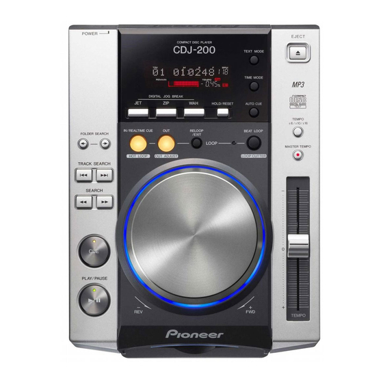
An LED or part of the display is lit while the corresponding key is held pressed. How to enter Display Check mode TEXT MODE Display Check mode POWER OFF POWER ON How to exit Display Check mode POWER OFF CDJ-200... - Page 52 $ The JOG LEDs corresponding to the direction and extent of rotation light up. POWER EJECT COMPACT DISC PLAYER TEXT MODE TIME MODE DIGITAL JOG BREAK HOLD/RESET AUTO CUE TEMPO IN/REALTIME CUE RELOOP BEAT LOOP FOLDER SEARCH /EXIT LOOP MASTER TEMPO HOT LOOP OUT ADJUST LOOP CUTTER TRACK SEARCH SEARCH PLAY/PAUSE TEMPO CDJ-200...
- Page 53 With the slider moved fully to the + PLAY/PAUSE side, all the segments are dark. With the slider moved fully to the - side, all the segments are lit. TEMPO EJECT All the FL display light up. • FL Display CDJ-200...
-
Page 54: Operation Check Mode For Player Section
Note: In this mode, auto setup is not performed when a disc is inserted. Playback in this mode does not mean audio playback but trace of the signal area on a disc. In playback, tracing is performed at double the speed of normal playback. No audio signal is output. CDJ-200... - Page 55 Pressing the MASTER TEMPO key during Test Operation mode turns the MASTER TEMPO LED off, and Player Operation mode (described above) is entered. Note: To start up the servos step by step in Test Operation mode, input the commands in the following order: Servo All Off, Focus On, Spindle Kick, then Tracking On. CDJ-200...
-
Page 56: How To Upgrade The Software Of The Microcomputer
However, its program is stored in the flash ROM of the Player microcomputer and is copied from there to the DSP processor when the power is turned on. 5. How to upgrade the software of the microcomputer TEXT MODE POWER CDJ-200 FL Display D OWN L O A D POWER ON Version up disc... -
Page 57: Error Codes/Detail Display Mode
To clear the error logs, while holding the TEXT MODE and BEAT LOOP keys pressed, press the POWER button. At this time, the settings for the AUTO CUE and TIME MODE keys are reset to those preset at the factory (AUTO CUE = OFF, TIME MODE = REMAIN). CDJ-200... -
Page 58: Power On Sequence
TOC positions are stored in memory with an accuracy of If the unit is in the program area, the stepper motor). it jumps back to the TOC area. First track is searched Playback (mute off) CDJ-200... -
Page 59: Disassembly
Diagnosis of MAIN Assy Remove the four screws. Remove the six screws. Bottom view Front side MAIN Assy Stand the MAIN Assy. Remove the control panel section. Control panel section Control panel section MAIN Assy Diagnosis CDJ-200... - Page 60 Remove the POM ring and JOG lens by unhooking the three hooks. Control panel section Jog dial POM ring JOG lens Control panel section Long thin pole Bottom view INDB Assy JOGB Assy SLDB Assy Bottom view JLED Assy KSWB Assy DISP Assy CDJ-200...
- Page 61 How to handle the float spring G5 To avoid losing the float spring G5, after removing it, put it on the hook of the float base 04 Assy. Hook Float base 04 Assy PCB stay MAIN Assy Float spring G5 CDJ-200...
- Page 62 RLYB Assy Earth spring The earth spring is attached between the mecha plate and the slot-in mecha SV Assy. Be sure not to lose it. Unhook the four hooks. Remove the slot-in mecha SV Assy. Slot-in mecha SV Assy CDJ-200...
- Page 63 Remove the traverse Assy 03-S. Hook Flexible cable for stepping motor FPC guard Stepping motor Traverse Assy 03-S Flexible cable for pickup Replace Note on the float rubber installation Hook Hook Pole of the float base 04 Assy ×2 Hook Bottom view CDJ-200...
-
Page 64: Parts
±2% ERR AMP PQ1M335M2SPQ (MAIN ASSY : IC104) • Regulator IC Pin Arrangement (Top view) Block Diagram NR 1 VO: DC output VIN: DC input GND 2 Control Block VC: ON/OFF control NR: Noise reduction VC 3 GND: Ground CDJ-200... - Page 65 RFDCI RFDC VDD5 AGCI CAV Servo CLV Servo Correction IO0B(TEZC) INVSEL Circuit IO1B(DFCT) TESTR IO2B(TRSR) VMDIR Synchronous Guarantee IO3B(HYS) EFM Decoder EMPH RESIN AVDD3 Audio Subcode Demodulator AOUT REFQ RFEQO LRCK RFRPI RFRP Digital AWRC DOUT TMAX EFM Slice CDJ-200...
- Page 66 Main beam input. To be connected to PIN diode D. FPI1 Main beam input. To be connected to PIN diode B. Subbeam input. To be connected to PIN diode F. Subbeam input. To be connected to PIN diode E. CDJ-200...
- Page 67 Audio data output. Which bit is first (MSB first or LSB first) can be selected, using a command. LR channel clock output. L ch: "L", R ch: "H" The output polarity can be inverted, using a command. LRCK 100 DOUT Digital-out output CDJ-200...
- Page 68 BTL pre and loading power supply − 25 DGND PWM block pre-ground 52 TKIN Tracking driver input Focus driver input 26 LDIN Loading driver input 53 FCIN − Reference voltage input 27 VC 54 DVCC PWM block control power supply CDJ-200...
- Page 69 Serial R-2R Interface 8bitREG R-2R V CC Power on reset Pin Function No. Pin Name I/O Pin Function Analog output Analog output Analog output − Power supply − Ground Serial data input Serial clock input Serial data load input CDJ-200...
- Page 70 Buffer Input/Output Erase Voltage Buffers Generator State Control BYTE Command RESET Program Voltage Register Generator Data Latch Chip Enable Output Enable Logic Y-Decoder Y-Gating Low Vcc Timer for Detector Program/Erase Address X-Decoder Cell Matrix Latch A18 to A0 1-8,16-25,48 CDJ-200...
- Page 71 21 A4 Address input 45 DQ15/A-1 I/O Data input/output / Address input − 22 A3 Address input 46 VSS Ground 23 A2 Address input 47 BYTE Selects 8-bit or 16-bit mode 24 A1 Address input 48 A16 Address input CDJ-200...
- Page 72 (144 QFP External SRAM0 120 MHz) BUFEN1_B BUFEN2_B IDE-DIOR SmartMedia Clock Translator IDE-DIOW Multiplied IDE-IORDY Interrupt Controller QSPI_DIN QSPI_DOUT QSPI QSPI_CS[3:0] Interface QSPI_CLK Audio Serial Audio Interface Interface EBUIN3/ADIN0_GP138 EBUIN4/ADIN1_GP139 RXD2/ADIN2/GP128 CTS2/ADIN3/GP131 TOUT1/ADOUT/GP135 Flash Memory/ MemoryStick/SecureDigital Card Interface Interface CDJ-200...
- Page 73 Driver IC muting control 1 SDRAS SDRAM RAS SDCAS SDRAM CAS SDWE SDRAM WE SDLDQM SDRAM LDQM GPIO5 Display microcomputer reset QSPI_CS0/GPIO29 DSP chip select QSPI_DOUT/GPIO26 DSP/DAC/StepperDA serial data output GPIO6 Audio muting control output DATA21 SDRAM/FLASH data input/output D5 CDJ-200...
- Page 74 PLLCOREVDD PLL power supply (1.8V) IDE-DIOW/GPIO14 TC94A15F bus #1 CRIN 16.9344MHz system clock input CS2/IDE-DIOR/GPIO13 TC94A15F bus #0 IDE-IORDY/GPIO16 TC94A15F bus #3 MCLK1/GPO39 DSP/DAC clock output 16.9344MHz MCLK2/GPO42 XTRIM/GPO38 PLAY control signal to the DSP TRST/DSCLK Connect to GND CDJ-200...
- Page 75 Address output to FLASH ROM(A7) 140 A7 Address output to FLASH ROM(A6) − 141 CORE-VDD Core power supply (1.8V) 142 A12 Address output to SDRAM(A4)/FLASH ROM(A11) 143 TEST1 Connect to GND. Mode select pin − 144 PAD-VDD I/O power supply (3.3V) CDJ-200...
- Page 76 Blink when WAH function is ON (Lights when HOLD function is ON) Blink when ZIP function is ON (Lights when HOLD function is ON) Blink when JET function is ON (Lights when HOLD function is ON) Lights when AUTO CUE function is ON CDJ-200...
-
Page 77: Panel Facilities
Turns the Master Tempo function ON/OFF (lights when half its length. (LOOP CUTTER) turned ON). 27. DIGITAL JOG BREAK buttons 12. BEAT LOOP indicator Turns each sound effect ON/OFF: JET, ZIP, WAH. Lights at the loop-in point during loop play. CDJ-200... - Page 78 Flashes when Digital Jog Break ZIP is turned on. 45. JET Flashes when Digital Jog Break JET is turned on. 46. A.CUE Lights when Auto Cue function is turned on. 47. REMAIN Lights when the track remaining time is displayed. CDJ-200...
- Page 79 CDJ-200...
- Page 80 • Before shipping out the product, be sure to clean the following positions by using the prescribed cleaning tools: Position to be cleaned Position to be cleaned Cleaning tools Cleaning tools Remark Remark Pickup leneses Cleaning liquid : GEM1004 Refer to "2.4 SLOT-IN MECHANISM SECTION" , "7.1.3 DISASSEMBLY". Cleaning paper : GED-008 CDJ-200...
Need help?
Do you have a question about the CDJ-200 and is the answer not in the manual?
Questions and answers