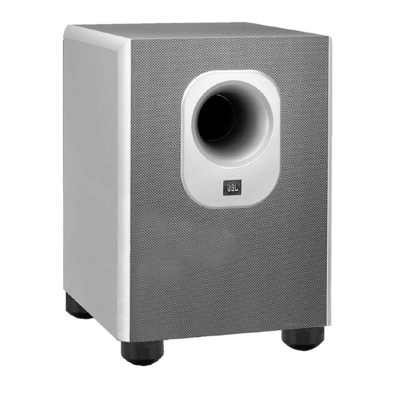
Summary of Contents for JBL SUB300
- Page 1 Surround Cinema SUB300 Amplifier/Subwoofer SERVICE MANUAL JBL Consumer Products 250 Crossways Park Dr. 10/2005 Woodbury, New York 11797 Rev2...
-
Page 2: Table Of Contents
Note: The SUB300 is part of the SCS300.7 system Satellite loudspeakers SCS300SAT: order JBL part# SCS300SAT-1 Center channel SCS300CEN: order JBL part# SCS200/300CEN-1 - CONTENTS - BASIC SPECIFICATIONS……………….….….….….…………….1 DETAILED SPECIFICATIONS ……..…………….……………..2 OPERATION ………….……………………………..…………….4 CONNECTIONS..………………………..………….…….………...5 BASIC TROUBLESHOOTING…..…………….….….…….……...7 TEST SET-UP AND PROCEDURE……………………………….8 EXPLODED VIEW/PARTS LIST…………………………………..9... - Page 3 SUB300 (SCS300.7sys) JBL SUB 300 150W Powered Sub/ Plate Amp LINE VOLTAGE Yes/No Hi/Lo Line Unit Notes Normal Operation US 120VAC/60Hz 108-132 Vrms Asia 100VAC/50Hz 90-110 Vrms Normal Operation EU 230VAC/50-60Hz 207-264 Vrms Normal Operation Normal operation, MOMS required QA Test...
- Page 4 SUB300 (SCS300.7sys) QA Test Parameter Specification Unit Limits Conditions Notes Transients/Pops ATO Transient mV-peak @ Speaker Outputs Turn-on Transient mV-peak @ Speaker Outputs AC Line cycled from OFF to ON Turn-off Transient mV-peak @ Speaker Outputs AC Line cycled from ON to OFF...
-
Page 5: Operation
(marked “Power” å) to the “ • ” used, switch the Master Power switch å to the Off position. (On) position to use the sub- woofer. The SUB300 subwoofer will automatically turn on or go into standby (sleep) mode when left in the auto mode (“Auto/On”... - Page 6 SUB300 (SCS300.7sys) DOLBY* DIGITAL OR DTS ® (OR OTHER DIGITAL SURROUND MODE) CONNECTION Frequency Effects channel. your receiver for 5.1-, 6.1- SUBWOOFER RECEIVER Connect this jack to the LFE or 7.1-channel operation as output or subwoofer output appropriate. The front left,...
- Page 7 SUB300 (SCS300.7sys) DOLBY PRO LOGIC (NON-DIGITAL) – SPEAKER LEVEL Use this installation method for Dolby Pro Logic applica- Right Front Left Front Center tions (not Dolby Digital, DTS or other digital processing), – – – where the receiver/processor does not have a subwoofer...
-
Page 8: Connections
SUB300 (SCS300.7sys) TROUBLESHOOTING If there is no sound from any owner’s manual for that electrical outlet, and is of the speakers: product for further informa- turned on (Power switch å tion. If the problem has fol- in the “ • ” position). -
Page 9: Test Procedure
SUB300 (SCS300.7sys) SUB300 TEST PROCEDURE SYSTEM AURAL SWEEP TEST Equipment needed: • Function/signal generator/sweep generator • Integrated Amplifier • Multimeter • Speaker cables General Unit Function (UUT = Unit Under Test) Auto-On switch – either position 1) From the signal generator, Connect both right and left line level inputs (RCA) to signal generator and UUT. -
Page 10: Exploded View
SUB300 (SCS300.7sys) SUB300 Exploded View SUB300 Cabinet Port Tube Not For Sale 249-ABS-00175 SUB300 Amplifier Not For Sale Main Body Plastic Foot (4) 321-ABS-00008 Foot Screw (4) 352-HM04030D500 Rubber Foot Base (4) Woofer & Amplifier Screw (15) 321-ABS-00009 352-AM04020D210 10" Woofer DCR=3.4Ω... - Page 11 SUB300 (SCS300.7sys)
- Page 12 SUB300 (SCS300.7sys)
- Page 13 SUB300 (SCS300.7sys)
-
Page 14: 120V Electrical Parts List
SUB300 (SCS300.7sys) SUB300 120v Electrical parts List Part Number Description Reference Designator Input/Main PCBs Resistors 110-14103j26 resistor 10K 1/4W ± 5% CF 26mm R503,504,10 R511 110-14222j26 resistor 2.2K 1/4W ± 5% CF 26mm 110-14432j26 resistor 4.3K 1/4W ± 5% CF 26mm... - Page 15 SUB300 (SCS300.7sys) 120v Electrical parts List cont'd Part Number Description Reference Designator Input/Main PCBs 135-3107m16 electrolytic 100uF 16V ± 20% C234 135-3107m35 electrolytic 100U 35V ± 20% C507,508 135-3225m50 electrolytic 2.2U 50V ± 20% C509 135-3226m16 electrolytic 22U 16V ± 20%...
- Page 16 SUB300 (SCS300.7sys) 120v Electrical parts List cont'd Part Number Description Reference Designator Module Class D DS-150 Capacitors 141-c0101k50 SMD capacitor 100pF 50V 10% 1206 NP0 141-c0220k50 SMD capacitor 22pF 50V 10% 1206 SMT NP0 141-c0561k50 SMD capacitor 560pF 50V 10% 1206 NP0 141-c5104m50 SMD capacitor 1206 Y5V 0.1uF 50V ±...
- Page 17 SUB300 (SCS300.7sys) SUB300 230v Electrical parts List Part Number Description Qty Reference Designator Input/Main PCBs Resistors 110-14103j26 Resistor 10K 1/4W ± 5% CF 26mm TAP R503,504,510 R511 110-14222j26 Resistor 2.2K 1/4W ± 5% CF 26mm TAP 110-14432j26 Resistor 4.3K 1/4W ± 5% CF 26mm TAP...
-
Page 18: 230V Electrical Parts List
SUB300 (SCS300.7sys) 230v Electrical parts List cont'd Part Number Description Qty Reference Designator Input/Main PCBs 132-273ja03 Mylar capacitor 0.027uF 100V ± 5% TAP C143 132-473ja03 Mylar capacitor 0.047uF 100V ± 5% TAP C216,217 135-3105m50 electrolytic 1U 50V ± 20% TAP... - Page 19 SUB300 (SCS300.7sys) 230v Electrical parts List cont'd Part Number Description Qty Reference Designator Module Class D DS-150 118-12062701j SMD Resistor 2.70K 1206 5% 118-12063000j SMD Resistor 300.0Ω 1206 5% 118-12063301j SMD Resistor 3.30K 1206 5% R14,15,27,28 118-12063902j SMD Resistor 39.0K 1206 5% 118-12064700j SMD Resistor 470Ω...
- Page 20 SUB300 (SCS300.7sys)
-
Page 21: 120V Schematics
SUB300 (SCS300.7sys) 120v SCHEMATIC PAGE 1... - Page 22 SUB300 (SCS300.7sys) 120v SCHEMATIC PAGE 2...
- Page 23 SUB300 (SCS300.7sys) 120v SCHEMATIC PAGE 3...
-
Page 24: 230V Schematics
SUB300 (SCS300.7sys) 230v SCHEMATIC PAGE 1... - Page 25 230v SCHEMATIC PAGE 2 SUB300 (SCS300.7sys)
-
Page 26: Packaging
SUB300 (SCS300.7 sys) SCS300.7 Packaging Warranty Card 405-000-00258 Speaker Wire 20 Feet (3) 166-020F84XX Owner’s Manual (120V) 406-000-00959 Speaker Wire 40 Feet (4) (230V) 406-000-00958 166-040F84XX Speaker Wire 15 Feet (2) 166-015F84XX RCA Cable 15 Feet 166-015F011 Floor Stand Adapter (6)


Need help?
Do you have a question about the SUB300 and is the answer not in the manual?
Questions and answers