Advertisement
Quick Links
Download this manual
See also:
Owner's Manual
T echnical
Manual
Table of Contents
Specification......................................1
Parts List ...........................................2
Adjustment........................................3
Case Outlines....................................3
PCB Assembly ..................................3~4
Schematic Diagram ..........................5~6
Specification
Continuous Power Output Stereo Mode
(20 - 20 kHz, <0.03% THD)
Bridged Mono Power Output
(20 - 20 kHz, <0.1% THD)
Total Harmonic Distortion
(20 Hz : 20 kHz, 8 ohms)
Intermodulation Distortion
(60 Hz : 7 kHz, 4 : 1)
Frequency Response (+0.5 db, -3 db)
Damping Factor (20-20,000 Hz, 8 ohms)
Speaker Impedance (combined load)
Signal to Noise Ratio (IHF A network)
Input Impedance/Sensitivity
Power Requirements
Power Consumption
Dimensions (W x H x D)
Weight (net)
SHINSEN-BLD. 4F 10-10 SHINSEN-CHO, SHIBUYA-KU,
TOKYO 150-0045, JAPAN
Quality Uncompromised
®
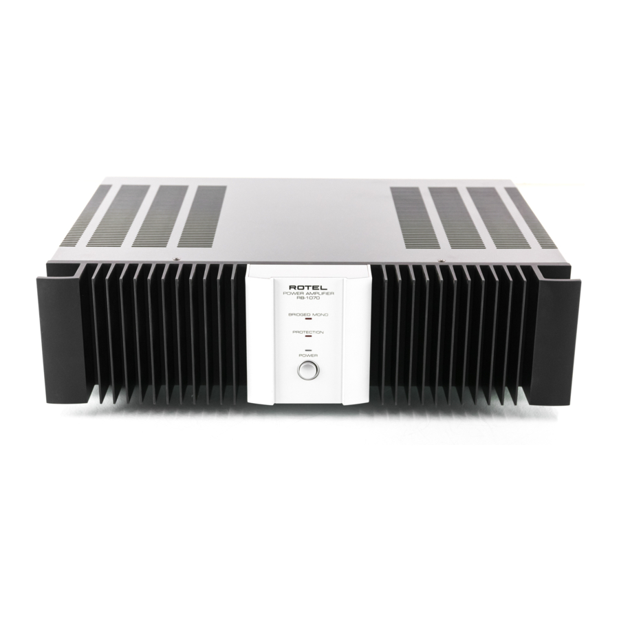
STEREO POWER AMPLIFIER
RB-1070
130 watts/ch into 8 ohms
300 watts/ch into 4 ohms
<0.03 %
<0.03 %
4 Hz - 100 kHz
500
4 ohms minimum
120 dB
33 k ohms/1.0 volt
USA: 115 volts, 60 Hz
Europe: 230 volts, 50 Hz
400 Watts
430 x 121 x 350 mm
16
x 4
x 13
15/16
3/4
3/4 in
11.9 kg/26.25 lb.
Serial. NO.
Beginning
Y-323A-00015C/S-S
Advertisement

Related Manuals for Rotel RB-1070


Summary of Contents for Rotel RB-1070
- Page 1 Quality Uncompromised ® T echnical STEREO POWER AMPLIFIER RB-1070 Manual Table of Contents Specification........1 Parts List ...........2 Adjustment........3 Case Outlines........3 PCB Assembly ........3~4 Schematic Diagram ......5~6 Specification Continuous Power Output Stereo Mode 130 watts/ch into 8 ohms (20 - 20 kHz, <0.03% THD)
-
Page 2: Parts List
Parts List SYMBOL PARTS NO. DESCRIPTION SYMBOL PARTS NO. DESCRIPTION X-1240-01 PCB ASSEMBLY C601,602 041 50BGF4R7M CAP,ELEC.50V4.7UF R805 053 CR14-104J-A R,CARBON 100K C603,604 044 TFKP2-2A681H CAP,FILM100V680PF R806 053 CR14-333J-A R,CARBON 33K C605,606 044 FSC160V221H CAP,STYROL160V220PF R807 053 CR14-104J-A R,CARBON 100K C607,608 041 25BGF100M CAP,ELEC.25V100UF... - Page 3 Case Outline PCB Assembly 2SA1016K 2SC2362K 2SA1209 2SC2911 2SA1376A 2SC3478A 2SD1953 2SA1667 2SC4381 2SA1492 2SC3856 Adjustment Instruments : DC milli–voltmeter Step Coupling Location Adjust Adjust for Notes : Prior to Bias Adjustment, run about 5minutes X-1240 PCB VR601 with rated output(8ohms) and warm up DC milli–voltmeter reads 4mV Power Transistor and Heat Sink.
- Page 4 Schematic Diagram...
Need help?
Do you have a question about the RB-1070 and is the answer not in the manual?
Questions and answers