Advertisement
Install guide 6036
Caution
• Your thermostat is a precise instrument, handle it with care.
• Turn off electricity to the appliance before installing or
PM
servicing thermostat or any part of the system.
• Do not turn electricity back on until work is completed.
• Do not short (jumper) across electric terminals at control on
furnace or air conditioner to test the system. This will damage
the thermostat and void your warranty.
• All wiring must conform to local codes and ordinances.
• This thermostat is designed for use with 24 volt AC and
millivolt systems. The thermostat should be limited to a
maximum of 1.0 amps; higher amperage may cause damage
to the thermostat.
ENGLISH
Advertisement
Table of Contents

Subscribe to Our Youtube Channel
Related Manuals for ritetemp 6036


Summary of Contents for ritetemp 6036
- Page 1 Install guide 6036 Caution • Your thermostat is a precise instrument, handle it with care. • Turn off electricity to the appliance before installing or servicing thermostat or any part of the system. • Do not turn electricity back on until work is completed.
- Page 2 Install guide 6036 To avoid electrical shock and to prevent damage to the furnace, air conditioner, Caution and thermostat, disconnect the power supply before beginning work. This can be done at the circuit breaker, or at the appliance. Tools You will need a Phillips screwdriver, Sheet rock Saw, level, Pencil.
- Page 3 • Loosen all screws on the old thermostat and remove it from the wall. Wall Cut Wall Opening Push top here The 6036 uses a cut-in type wall box (a type of electrical box that attaches to the drywall, not the studs). Remove the Thermostat thermostat unit from the wall box as shown.
- Page 4 Cut Wall Opening cont • Use a stud finder to locate stud positions. • Place the cutting template so that the 6036 will be located between the studs [no closer than 2" from a stud] but as close to the thermostat wires as possible.
-
Page 5: Before You Connect Wires
• Do not to damage the labels for each wire in handling. • Fan wires out as illustrated with 6036 above the wall box. • Wires will need to dress behind the 6036 and into the wire hole • Use the Step-By-Step diagram as your guide. - Page 6 Before you Connect Wires cont • Remember to insert the wire in the terminal and tighten the screw securely. • You will need to set Configuration Jumpers per the Step-By-Step diagram. • Set these jumpers first before connecting wires. • Needle-nose pliers may be needed to modify jumper locations.
-
Page 7: Find The Set-Up Diagram For Your System
Find the set-up diagram for your system • Find the reference page with your wiring C W RH Go To Page 19 diagram and jumper set-up information. F r o m 2 Wire F u r n a c e Remember, the C wire is optional. - Page 8 No backlight means low battery. Mount the 6036 in wall box • Insert the top of the 6036 into the wall box, with the wires coming out the back of the unit.
-
Page 9: Check Unit
It will take 1 hour to equalize to the correct temp reading. Congratulations, you have successfully installed your unit. Please proceed to the OPERATING Guide to initialize the 6036. NOTE: If you have labeled your wires, follow the correct Step-By-Step, and... -
Page 10: Power Options
Power Options BATTERIES ONLY - This thermostat can run on batteries only using 2AA alkaline batteries. The batteries will last at least 1 year; replace the batteries once a year or when the low battery icon comes on the display. If the batteries are not replaced, the thermostat will shut off the HVAC and then stop working. - Page 11 6036. This connects the Heater Power to the thermostat. JUMPERS STEP 2 - Connect the W wire to the W on the 6036. This connects the heater control line to the 6036. STEP 3 - Set Config jumpers per this diagram.
- Page 12 6036. This connects to the Cooler compressor. STEP 3 - Connect the RH wire to the RH terminal and the RC wire to the RC terminal on the 6036. This connects the Heater and Cooler Power. STEP 4 - Connect the G wire to the G terminal on the Thermostat.
- Page 13 STEP 1 - Connect O wire to the O terminal or B wire to the B terminal on the 6036. (If you have both O and B -connect O wire to O terminal DO NOT connect B to B terminal - see pg 24 Trane for B wire terminal) STEP 2 - Connect the W2 wire to W2 on the 6036.
- Page 14 Motor driven Valve- Connect the R (or RH) wire to the RH SET JUMPERS terminal on the 6036. Connect the W wire to the W terminal on the 6036. Connect the remaining wire to the A terminal. Solenoid valve -Connect the R (or RH) wire to the RH terminal on the 6036.
-
Page 15: Wire Reference
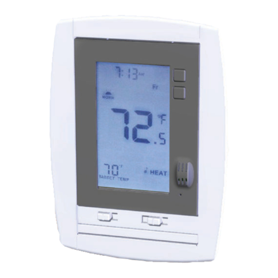
6036 Features This thermostat can be used with all millivolt and 24VAC heating and cooling systems. It cannot be used with line voltage systems. This thermostat is digital and your desired heat or cool temperatures can be easily be set on the large touch screen with the UP/DOWN arrows. -
Page 16: Jumper Reference
3 Wire Zoned Hot Water Solenoid Valves W or W1 Y (the 3rd wire) W Jumper Reference Configuration jumpers allow your 6036 to be adapted to many different HVAC control applications. 2 4 5 RESET UNIT AFTER CHANGING JUMPERS HEAT TYPE HVAC...
Need help?
Do you have a question about the 6036 and is the answer not in the manual?
Questions and answers