Table of Contents
Advertisement
Advertisement
Table of Contents

Related Manuals for TC Electronic INTONATOR


Summary of Contents for TC Electronic INTONATOR
- Page 1 English USER’S MANUAL INTONATOR VOCAL INTONATION PROCESSOR...
-
Page 3: Important Safety Instructions
IMPORTANT SAFETY INSTRUCTIONS The lightning flash with an arrowhead symbol The exclamation point within an equilateral triangle within an equilateral triangle, is intended to alert is intended to alert the user to the presence of the user to the presence of uninsulated "dan- important operating and maintenance (servicing) gerous voltage"... - Page 4 This equipment has been tested and found to comply with the limits for a Class B Digital device, pursuant to part 15 of TC Electronic A/S, Sindalsvej 34, 8240 Risskov, Denmark, the FCC rules. hereby declares on its own responsibility that following product: These limits are designed to provide reasonable protection against harmful interference in residential installations.
-
Page 5: Table Of Contents
Signal flow diagram ....9 BASIC OPERATION Intonator Setup ....10 Displays and Keyboard ... . 13 Correction Processing . -
Page 7: Introduction
Very often the strongest energy and timing occurs during the first two or three takes. Further tracking just to nail a few “out of pitch” notes, often kills the initial energy and fresh feeling. Keep the “good track” and use the Intonator to correct the few out of pitch notes there might be. -
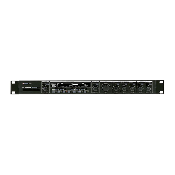
Page 8: Front Panel
SIGNAL LED DIGITAL LOCK displays Input Pitch in Chromatic “Easy touch” - type. Present Input signal. Shows when the Intonator is and Manual modes. When in Turn on the machine @ -22dBFS locked to an external digital "Setup mode" this area indicates with a single light touch. - Page 9 FRONT PANEL SCALE/SETUP MANUAL CORRECTION PROCESSING AUTOMATED DYNAMICS DIAL MANUAL NOTE HOLD CORRECTION DE-ESS LOW CUT FILTER SCALE HOLD BYPASS Adaptive SETUP Active Manual MEDIUM FAST SLOW 265/ cent rel. rel. rel. ALPHA DIAL PITCH WINDOW ATTACK AMOUNT DE-ESS FREQUENCY SCALE/SETUP CORRECTION PROCESSING AUTOMATED DYNAMICS...
-
Page 10: Rear Panel
Pin 2 is »hot« on all XLR’s (IEC and AES standards). For soldering instructions please refer to page 30. If you are connecting the Intonator to unbalanced equipment, you must tie pins 1 and 3 together in the cable ends away from the Intonator. -
Page 11: Signal Flow Diagram
SIGNAL FLOW Normal Mode INPUT PPM Left In Level Right Input Selector DELAY Left ANALOG ANALOG PITCH ADAPTIVE INPUTS OUTPUTS CORRECTION LOW CUT ESSER [balanced] Right [balanced] Bypass Digital Output Digital Input AES/EBU Dither [AES] [AES] Digital Output S/PDIF Digital Input [S/PDIF] [S/PDIF] ADAT... -
Page 12: Intonator Setup
1. Connect the ADAT optical Out to the Intonator optical In. 2. Connect the Intonator optical Out to the ADAT optical In. MIDI 3. Set ADAT In/Out channels in the Setup pages. 4. Connect the Intonator MIDI Out to the MIDI In of the ADAT ADAT sequencer. - Page 13 Page 3 - see below. Analog The INPUT knob is only active when analog Inputs are used. Mode - Page 3 Select between running the Intonator at: AES - S/PDIF 44.1/48kHz (normal) or When AES or S/PDIF is selected, Sync will automatically switch 88.2/96kHz (double rate).
- Page 14 Since the material you often would like to process with the Correction Amount. Select MIDI channels 1-16 or Off. Intonator is mono (i.e. single vocals) we found that splitting the Control and MIDI Pitch channel cannot be the same. unit in a Pitch Correction section and Dynamics section would be useful.
-
Page 15: Displays And Keyboard
DISPLAYS & KEYBOARD Input Pitch / Correction Display PITCH/CORRECTION STATUS SCALE FLAT PITCH SHARP DIGITAL LOCK PITCH STATUS SCALE FLAT PITCH SHARP MIDI INPUT CORRECTION DIGITAL LOCK PITCH MIDI OVERRIDE -200 200+ CENT MIDI INPUT CORRECTION MIDI OVERRIDE Keyboard -200 200+ CENT Correction bar... -
Page 16: Correction Processing
CORRECTION PROCESSING MANUAL/AUTOMATIC mode switch HOLD key MANUAL CORRECTION PROCESSING MANUAL NOTE HOLD CORRECTION HOLD BYPASS BYPASS key MEDIUM AMOUNT knob FAST SLOW cent rel. rel. PITCH WINDOW ATTACK AMOUNT PITCH knob WINDOW knob ATTACK knob Manual Pitch Bend Attack The user can use this control in both Manual and Automatic The ATTACK control allows the user to change how fast the modes to add extra pitch bend to the Input signal. - Page 17 CORRECTION PROCESSING AMOUNT Amount Control MIDI 127 Rel. 6 MIDI 64 Rel. 3 MIDI 25 MIDI 0 Rel. 0 MIDI 10 Out of Tune Amount...
-
Page 18: Automated Dynamics
Low Cut filter. generated by the “s” sound. The Adaptive Low Cut filter in the Intonator allows you to set the Threshold frequency relatively high without fearing that it Basic operation will cut off important low frequencies. -
Page 19: Custom Scales
OPERATION This chapter will explain how to operate the Intonator. You should get acquainted with the different ways of working the unit. Different tasks require different operation procedures. We will explain: using Custom scales, Automatic mode, Manual mode, and operation via MIDI. -
Page 20: Manual Mode
OPERATION major. Without hesitation you hook up the Intonator . . . Manual Mode Solution : Press the MANUAL key in the Correction Processing section on Automatic mode is the best tool to fix the uncomfortable pitch the front panel to activate Manual mode. The MANUAL ON mistakes in this track. - Page 21 OPERATION There are two ways you can fix this mistake: by ear or by sight. By ear: Use the manual pitch knob on the front panel to correct the pitch. Turn the knob to the left if the “out of tune” note is sharp or to the right if the note is flat.
-
Page 22: Midi
Automatic mode to the uncorrected signal. Control channel. The Input pitch and pitch-bend information will be transmitted via a separate channel; - Work with the Intonator in the Automatic mode until you the MIDI Pitch channel. With this information recorded have the best settings possible. -
Page 23: Midi Continuous Controllers
MIDI CONTINUOUS CONTROLLERS MIDI CC TABLE - Overview Scale Selection When pressing one of the SCALE keys a cc message will be sent. When receiving a message via MIDI it will be interpreted as Parameter Data Range if a key on the Front panel had been pressed. Scale Selection Pitch Window Parameter Data Range... -
Page 24: Attack Control
MIDI CONTINUOUS CONTROLLERS Attack Control MIDI Window MIDI Window Parameter value value value value Parameter Data Range cc #21 58.8 121.4 cc #22 0 -127 60.0 123.8 instantaneous 61.2 126.2 62.4 128.6 63.5 131.0 64.7 133.3 very slow 65.9 135.7 67.1 138.1 68.2... -
Page 25: Manual Mode
MIDI CONTINUOUS CONTROLLERS Manual Mode MIDI MIDI Amount Amount Parameter value value value value The unit responds to the following message values for cc #23 changing between Manual and Automatic modes. 103.1 178.3 104.4 180.6 Parameter Data Range 105.7 182.8 107.1 185.1 cc #24... -
Page 26: Pitch Bypass
MIDI CONTINUOUS CONTROLLERS Pitch Bypass De-ess key The unit responds to the following message values for The unit responds to the following message values for changing between Manual and Automatic modes. turning the De-Ess function on and off. Parameter Data Range Parameter Data Range cc #26 0 -127... -
Page 27: Tuning Reference Adjustment
MIDI CONTINUOUS CONTROLLERS Input Pitch Tuning Reference Adjustment Tuning reference is available as part of the MMA MIDI The same pitch that is displayed on the front panel is Output specification. through MIDI. When a pitch is detected, a note on message is sent, with velocity 0x7Fh, along with a continuous stream of pitch bend messages at a specified time interval. -
Page 28: Midi Implementation Chart
APPENDIX - MIDI IMPLEMENTATION CHART VOCAL INTONATION PROCESSOR - JUNE 14th - 1999 Function Transmitted Recognized Basic Channel Default Changed 1-16 1-16 Mode Default Messages Altered Note Number True Voice Velocity Note ON Note OFF After Touch Key’s Ch’s Pitch Bend Control Change Prog Change True#... -
Page 29: Appendix
APPENDIX - Technical specifications Digital Inputs and Outputs Connectors: XLR (AES/EBU), RCA Phono (S/PDIF), Optical (Tos-link, ADAT), Formats: AES/EBU (24 bit), S/PDIF (24 bit), EIAJ CP-340, IEC 958, EIAJ Optical (Tos-link), ADAT Lite pipe (24 bit) Output Dither: HPF/TPDF dither 8-24 bit, independent dithered Output Word Clock Input: RCA Phono, 75 ohm, 0.6 to 10 Vpp Sample Rates:... -
Page 30: Self Test
S/PDIF I/O test Push the ALPHA dial knob to start the test. Connect a RCA cable from the Intonator S/PDIF Input directly to Push the keys one by one. the Intonator S/PDIF Output. Push the ALPHA dial knob to start the test. -
Page 31: Soldering Instructions
APPENDIX Soldering instructions MIDI Cable DIN CONNECTOR DIN CONNECTOR 5POLE - MALE 5POLE - MALE max. 10m 45 degrees 45 degrees SHIELDED CABLE (3 or 5 wires + screen) XLR - XLR Jack (unbalanced) - XLR Jack (balanced) - XLR Pin 1 - Pin 1 (Ground) Sleeve - Pin 1 (Ground) Sleeve - Pin 1 (Ground) -
Page 32: Glossary
APPENDIX Glossary AES/EBU Dither Professional digital in/out standard, using balanced XLR cables. Going from one type of bit resolution to a lower, e.g. from 24 bit to16 bit, you actually loose 8 bits of information. The process of The AES/EBU format can Output 24 bit 96kHz. cutting off bits is called truncation and it introduces digital distortion of low level signals, due to the lack of complete signal S/PDIF...
Need help?
Do you have a question about the INTONATOR and is the answer not in the manual?
Questions and answers