Table of Contents
Advertisement
Quick Links
Advertisement
Table of Contents

Related Manuals for TC Electronic G-Major


Summary of Contents for TC Electronic G-Major
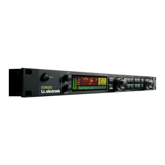
- Page 1 G•Major GUITAR EFFECTS PROCESSOR U U S S E E R R ’ ’ S S M M A A N N U U A A L L...
-
Page 3: Important Safety Instructions
IMPORTANT SAFETY INSTRUCTIONS The lightning flash with an arrowhead The exclamation point within an symbol within an equilateral triangle, is equilateral triangle is intended to alert intended to alert the user to the the user to the presence of important presence of uninsulated "dangerous volt- operating and maintenance (servicing) age"... - Page 4 15 of the FCC rules. These limits are designed to provide Certificate Of Conformity reasonable protection against harmful TC Electronic A/S, Sindalsvej 34, 8240 interference in residential installations. This Risskov, Denmark, hereby declares on own responsibility that following products:...
-
Page 5: Table Of Contents
Assigning Modifiers ....24 How To..Examples on various operations ..25 TC Electronic, Sindalsvej 34, DK-8240 Risskov – tcdk@tcelectronic.com English Version Rev 7.1 – SW – V 1.26... - Page 6 INTRODUCTION Congratulations on the purchase of your G•Major Effects processor. If you have never used a multi-effects processor with your guitar rig, you might be wondering at this point whether you have placed yourself in a position where you have days of work ahead of you, until your G•Major behaves as you please and adds to your creativity.
-
Page 7: Introduction
TC Electronic is all for your benefit. Though each product is unique it is worth noticing the success and achievement gained on other products from TC Electronic. Prices won for astounding Reverb quality, Compression techniques and numerous other classic TC effects such as Dynamic Delay and Chorus guaranties also the quality of this product. -
Page 8: Front Panel Overview
FRONT PANEL OVERVIEW POWER KEY DI LED PRESET NUMBER On/Off switch for the unit. Indicates that external digital When steady the currently Clock Input is selected. recalled preset number is INPUT LEVEL KNOB displayed. When Adjusts the Input level. TUNER previewing presets the Range: 24dB The G•Major holds a Tuner. - Page 9 FRONT PANEL OVERVIEW FRONT PANEL KEYS ENTER for confirmation. To do GENERAL INFORMATION ROUTING so use the PARAMETER A single click will activate/ Press to access the Routing wheel in the Effects section to deactivate the effect. Double section. This is where you select letter-space and the clicking on the key will enter select the routing of your effect...
-
Page 10: Rear Panel Overview
REAR PANEL Balanced Digital MIDI External Power Switch Balanced Jack S/PDIF In, Out, Thru Control Input Jack Analog Input/ 100 - 240V Analog Relay Outputs Output Inputs Jack MIDI Cable Note! The analog Input and Output connectors DIN CONNECTOR DIN CONNECTOR 5POLE - MALE 5POLE - MALE on the G•Major are balanced 1/4”... -
Page 11: Signal Flow Diagram
SIGNAL FLOW... -
Page 12: Basic Setups
G•Major. This will give you the maximum benefit from all effect algorithms. As stated several times in this manual, you should NOT worry about coloring of your sound as TC Electronic uses top quality converters that does NOT color your tone. - Page 13 BASIC SETUPS Connecting and Setting up the G•Major Parallel Setup using a Line Mixer • Connect the Output of your preamp to the Input of the Line Mixer. • To be able to switch preamp channels with the G•Major connect the Relay Jack connection on the G•Major to the channel switching jacks on the preamp.
-
Page 14: The Display
The two arrows will both be lit when the instrument is in tune. Input Overload LEDs If a TC Electronic G•Minor MIDI pedal (optional) The Overload LEDs indicates one of two is used you can also have the Tuner displayed situations: in the Pedal. -
Page 15: Preset Handling
THE DISPLAY PRESET HANDLING Preset types MIX Meter: Indicates the parameter position of the Mix level User presets - RAM in the block currently being edited. User presets that can be edited and stored in any User location. You can store up to 100 user DAMP presets in the User bank. -
Page 16: Store
PRESET HANDLING I/O SETUP Store I/O Setup To store a preset with the same name: In the I/O menu you will find all I/O related • Press STORE. parameters such as Input/Output settings, If the preset you are about to store is a analog/digital, Status Bit and Dither. -
Page 17: Utility & Midi
I/O SETUP MIDI/UTIL Please note that when using internal All parameters in the I/O menu are “general” clock with external digital audio, the parameters that are not stored with the incoming digital audio must be in sync presets. with the G•Major internal clock in order MIDI Channel to avoid slip-samples. - Page 18 MIDI/UTIL the pedal is pressed. Alternating pedal types MOD Master “stays connected” when pressed, and must be Range: Read/Ignore pressed again to be deactivated. Default setting If you are not acquainted with Modifiers you is Expression. can read about them in the Modifier Section of this manual.
-
Page 19: The Tuner
Tuner Mode The G•Major Tuner and the G•Minor Pedal Sets the mode of the Tuner. Choose between If using the optional TC Electronic G•Minor two modes: Pedal the Tuner is displayed in the pedal as well. Fine Tune Maximum accuracy. -
Page 20: Midi Mapping
MIDI/UTIL MIDI MAPPING Reset MIDI Map By resetting the MIDI map incoming program What is MIDI mapping? changes will be mapped 1 to 1 factory bank, With the G•Major it is possible to map an 2 to 2 factory bank and so forth. incoming program change from 1 to 128 to recall any Factory or User preset. -
Page 21: Levels All Menu
LEVELS ALL & RELAY 1+2 Basic Operation A few comments regarding the Kill Dry function • Press the LEVELS ALL key to enter this and a parallel setup. First of all: menu. • In such a setup we recommend using the •... - Page 22 CHANNEL SWITCHING & TAP TEMPO Y-Splitter Cable Stereo to Stereo • Connect the Stereo jack to the Switch Out connection on the G•Major rear panel. Jack Cable • Connect the two mono jacks (or the stereo jack depending on the used cable) to the channel switching connectors on the combo RING RING...
-
Page 23: Routings
ROUTINGS Routing Menu Parallel The Parallel routing still allows serial based The G•Major holds three different effects effects like the Noise Gate, Compressor and routings. The Routings can be stored with the Tremolo to be connected in serial but preset. However you can also choose to fixate additionally connects the Pitch, Chorus, Delay your favorite routing by utilizing the "Routing and Reverb in a parallel setup. -
Page 24: Tap Tempo Menu
CONTROLLING THE G•MAJOR Introduction • “Learning” will now no longer blink and the G•Major has recognized your external If you have played around and listened to the controller. G•Major and maybe programmed a few presets Pedal you are probably anxious to get control of the When “Pedal”... -
Page 25: Assigning Modifiers
CONTROLLING THE G•MAJOR CC value or pedal connected to the Pedal * A dedicated response curve for each of the Input. A MIDI CC value above 64 will set the level parameters in the MOD menu is current preset to 0dB. A MIDI CC value below available. - Page 26 CONTROLLING THE G•MAJOR • “Learning” will now no longer blink and the Expression pedal/Modifier Input is at maximum G•Major has recognized which external position. controller you want to control the Modifier with and which MIDI CC value the device is sending if any.
-
Page 27: How To
HOW TO How to get started prefer. • Connect the G•Major according to your setup • The display now shows either Pedal, if that as described on pages 10/11 and power on. was the used controller device, or it shows •... - Page 28 HOW TO Matching the speed of a Rhythmic Tremolo or Vibrato to a MIDI sequence • Connect the MIDI Output of your sequencer or other device sending out the MIDI Clock you wish the G•Major to sync up to, to the MIDI Input of the G•Major.
-
Page 29: Effect Blocks
EFFECT BLOCKS NOISE GATE Introduction Introduction A Noise Gate is generally used to attenuate the Basic Operation of the Effect Menus signal when you don’t play the guitar. This way The six (or seven including Noise gate) effect you can avoid hearing the entire hiss, hum and keys on the front panel, all work as follows: other noise you might have on your system. - Page 30 NOISE GATE & EQ Max. Damping EQ Active Range: 0dB to 90dB Activate/deactivates the EQ. This parameter determines how hard the signal Please note that though the EQ is accessed via should be attenuated when below the set the Noise Gate key, the On/Off state of the EQ Threshold.
-
Page 31: Compressor
COMPRESSOR Introduction Illustration A Compressor is used to reduce the dynamic content of a signal. How can this improve your guitars appearance in the overall sound? There are situations where a compressor should not be applied on the guitar and there are definitely situations where it is the key to letting the guitar stand out and appear rock solid. -
Page 32: Chorus
CHORUS Introduction Tempo A Chorus/Flanger is basically a short Delay that Range: 1/32T to 1 Bar or Ignored is modulated by an LFO (Low Frequency The Tempo parameter sets the relationship to Oscillator). the global Tempo. The difference between Chorus and Flanging is the applied Delay time and the Feedback When set to anything else than Ignored parameter in the Flanger. - Page 33 CHORUS Advanced Chorus perceived Chorusing effect. When Golden Ratio is “ON” this value is automatically calculated. - CHO/FLA Block Golden Ratio is a feature inherited from the classic TC 2290 processor. Speed Range: 0.050Hz to 19.95Hz Phase Reverse The Speed of the Chorus, also known as Rate. Range: Off/On Reverses the processed Chorus signal in the The speed of this effect block is either...
-
Page 34: Flanger
FLANGER Classic Flanger FB Hi Cut - CHO/FLA Block Range: 19.95Hz to 20kHz Speed A parameter that can attenuate the high-end Range: 0.050Hz to 19.95Hz frequencies of the resonance created via the The speed of the Flanger, also known as Rate. Feedback parameter. -
Page 35: Vibrato
FLANGER VIBRATO Vibrato Feedback - CHO/FLA Block Range: -100 to 100 A Vibrato effect modulates the incoming pitch. Controls the amount of Feedback/Resonance The result is similar to the vibrato technique of the short modulated Delay that causes the used by vocalists. As opposed to a Chorus Flange effect. -
Page 36: Resonance Filter
RESONANCE FILTER Resonance Filter Auto Resonance Filter - FILTER/MOD Block - FILTER/MOD Block The G•Major Resonance filter is basically a Hi The Auto Resonance filter will create an effect Cut filter with adjustable Q-factor (Resonance). similar to a Touch Wah. The sweep through a With increased Resonance value, the filter peak frequency range is controlled via the dynamics at the cutoff frequency gets very narrow and... -
Page 37: Phaser
PHASER Vintage Phaser/Smooth Phase Reverse Range: On/Off Phaser An LFO phase change that causes a small - FILTER (MOD Block) Delay in one of the waveform starting points. Two effective good phaser types. The Vintage When applied the left and right Outputs will Phaser will give you the phasing effect similar start the current waveform at two different to the one found in old stomp boxes. -
Page 38: Tremolo
TREMOLO PANNER Tremolo Panner - - FILTER/MOD Block FILTER/MOD Block A Tremolo is basically a change of level The panner simply pans the signal from Left controlled by an LFO. The G•Major holds channel to the Right. variations from soft and smooth to hard and aggressive Tremolo. -
Page 39: Ping Pong
DELAY Introduction Ping Pong The G•Major holds 3 different Delay modes that With the PingPong Delay line you are able to cover not only your basic needs, but also Delay pan the repeats from left to right if you are effects you until now maybe thought of as using a stereo setup. -
Page 40: Delay
DELAY Out level The Release parameter determines how fast Range: -100 to 0dB the Output of the Delay repetitions returns to Sets the overall Output level of this block. “normal” after attenuation of these repeats have ceased. Dynamic Delay FB Hi Cut The Dynamic Delay initially introduced in the Range: 2.00kHz to 20kHz well-recognized TC 2290, is a function that... -
Page 41: Pitch Detune
DELAY DlyTime 2 Range: 0 to 1800ms Sets the Delay time of the second Delay Line. Tempo Range: 1/32T to 1 Bar or Ignored The Tempo parameter sets the relationship to the global Tempo. When set to anything else than Ignored the tempo defined by the Speed parameter is ignored. -
Page 42: Whammy
PITCH Detune Whammy A Detune effect has a sound that to some The Whammy effect gives you the opportunity extend can be associated with a Chorus effect. to control the pitch of an added voice with an The source signal is split and a specified external MIDI Expression pedal. -
Page 43: Pitch Shifter
PITCH Pitch Shifter Level 1 Range: -100 to 0dB With the G•Major Pitch Shifter you are able to Sets the Level for Voice 1. add 2 voices, each with a fixed pitch within +/- one octave from the Input note. The processing Level 2 of the G•Major is at a speed where you will Range: -100 to 0dB... -
Page 44: Reverb
REVERB Spring Room Level Range: -100 to 0 The Spring algorithm is designed to reproduce This parameter adjusts the Reverb Tail level. the sound of the old spring reverbs, such as the Lowering the Room Level will give you a more ones used in vintage guitar amps. - Page 45 REVERB Hall Reverb Lev Range: -100 to 0 Decay The level of the Early Reflections. Range: 0.1 to 20s The Decay parameter determines the length of Diffuse the Reverb Tail. The length is defined as the Range: -25 to 25 time it takes for the Reverb Tail to decay Allows fine-tuning of the density of the Reverb approximately 60dB.
- Page 46 REVERB Room Room Level Range: -100 to 0 Decay This parameter adjusts the Reverb Diffuse field Range: 0.1 to 20s level. Lowering the Reverb Level will give you a The Decay parameter determines the length of more ambient sound, since the Early Reflection the Reverb Diffuse field.
- Page 47 REVERB Plate Room Level Range: -100 to 0 Decay This parameter adjusts the Reverb Diffuse field Range: 0.1 to 20s level. Lowering the Reverb Level will give you a The Decay parameter determines the length of more ambient sound, since the Early Reflection the Reverb Diffuse field.
-
Page 48: Appendix
APPENDIX - MIDI IMPLEMENTATION CHART Guitar Effects Processor G•Major - February 2002 Function Transmitted Recognized Remarks Basic Channel Default Changed 1-16 1-16 Mode Default Messages Altered Note Number True Voice Velocity Note ON Note OFF After Touch Keys Ch’s Pitch Bend Control Change 0-127 0-127... -
Page 49: Technical Specifications
APPENDIX - TECHNICAL SPECIFICATIONS Digital Inputs and Outputs Connectors: RCA Phono (S/PDIF) Formats: S/PDIF (24 bit), EIAJ CP-340, IEC 958 Output Dither: HPF/TPDF dither 24/20/16/8 bit Sample Rates: 44.1 kHz, 48 kHz Processing Delay: 0.1 ms @ 48 kHz Frequency Response DIO: DC to 23.9 kHz ±... -
Page 50: Preset List
PRESET LIST G-Major Verb & Slap Lush Chorus Clean Reverb Formerly Known As? Sheryls Sound Swell Delays Tremolo Pedal Speed Wet Delays So Scho Clean Verb & Dly Scotty's Blues Tape Flange & Delay Straight Lead Lone Flanger Funky Thang... -
Page 51: Frequently Asked Questions
FREQUENTLY ASKED QUESTIONS This section give answers to some of the Amp switching of specific analog preamps most frequently asked questions regarding Contact the amp manufacturer to get the G•Major. More information can be found schematics on your specific preamp. Page 19 via TC Support Interactive, which can be of this manual explains how the relays of the accessed via www.tcelectronic.com... - Page 52 FREQUENTLY ASKED QUESTIONS have a variable mix knob, so that you can Conclusion - The G•Major will work with both control how much of the effect you want mixed serial and parallel loops but for the above in with the dry signal. mentioned reasons we recommend using the In a parallel loop situation you wish to avoid G•Major in a true serial loop/setup if possible.
Need help?
Do you have a question about the G-Major and is the answer not in the manual?
Questions and answers