
Related Manuals for Whirlpool RS160LXT

Summary of Contents for Whirlpool RS160LXT
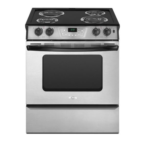
- Page 1 CONSUMER SERVICES TECHNICAL KR-38 EDUCATION GROUP PRESENTS SLIDE-IN ELECTRIC RANGE Models RS160LXT*, RY160LXT* JOB AID Part No. 8178710...
- Page 2 FORWARD This Whirlpool Job Aid “Slide in Electric Range” (Part No. 8178710), provides the In-Home Service Professional with information on the installation, operation, and service of the Slide in Electric Range. For specific information on the model being serviced, refer to the “Use and Care Guide,”...
-
Page 3: Table Of Contents
TABLE OF CONTENTS Page GENERAL ..........................1-1 Slide in Range Safety......................1-1 Model & Serial Number Designations ................1-2 Model & Serial Number Label And Wiring Diagram Locations ........... 1-3 Specifications ........................1-4 INSTALLATION INFORMATION .................... 2-1 Installation Requirements....................2-1 Location Requirements ...................... - Page 4 COMPONENT TESTING ......................5-1 Infinite Switch ........................5-1 Oven Temperature Sensor ....................5-2 Oven TOD .......................... 5-2 Bake Element ........................5-3 6 Inch & 8 Inch Coil Elements .................... 5-3 Broil Element ........................5-4 Cooling Fan Motor......................5-4 Door Latch Assembly Switch....................5-5 DIAGNOSTICS &...
-
Page 5: General
GENERAL SLIDE-RANGE SAFETY Your safety and the safety of others are very important. We have provided many important safety messages in this manual and on the appliance. Always read and obey all safety messages. This is the safety alert symbol. This symbol alerts you to potential hazards that can kill or hurt you and others. -
Page 6: Model & Serial Number Designations
MODEL & SERIAL NUMBER DESIGNATIONS MODEL NUMBER PRODUCT IDENTIFICATION R = ELECTRIC RANGES S = GAS RANGES G = WHIRLPOOL GOLD PRODUCT IDENTIFICATION A = ACCESSORY K = KITS B = BUILT-IN M = MV COMBO C = COOK TOP... -
Page 7: Model & Serial Number Label And Wiring Diagram Locations
MODEL & SERIAL NUMBER LABEL AND WIRING DIAGRAM LOCATIONS The Model/Serial Number label and Wiring Diagram locations are shown below. Wiring Diagram Location Model & Serial Number (On Back Side Of Storage Drawer) Label Location... -
Page 8: Specifications
SPECIFICATIONS Model RS160LXT, RY160LXT Color Q (wht), B (Blk), S (SS) Model Description Slide-In 30” Electric Coil, Pyro COOKTOP l i o " 6 l i o " 8 l i o Controls c t i OVEN & n i l... -
Page 9: Installation Information
INSTALLATION INFORMATION INSTALLATION REQUIREMENTS Parts needed Tools and Parts Gather the required tools and parts before start- If using a power supply cord: ing installation. Read and follow the instructions • A UL listed power supply cord kit marked for provided with any tools listed here. -
Page 10: Location Requirements
Mobile home installations require: Location Requirements • When this range is installed in a mobile home, it must be secured to the floor during IMPORTANT: Observe all governing codes transit. Any method of securing the range and ordinances. is adequate as long as it conforms to the • It is the installer’s responsibility to comply standards listed above. -
Page 11: Product Dimensions
Cabinet Dimensions Product Dimensions Cabinet opening dimensions shown are for 25" (64 cm) countertop depth, 24" (61 cm) base cabinet depth and 36" (91.4 cm) countertop height. If installing a range hood or microwave hood combination above the range, follow the range hood or microwave hood combination instal- lation instructions for dimensional clearances above the cooktop surface. -
Page 12: Electrical Requirements
• Allow 2 to 3 ft (61.0 cm to 91.4 cm) of slack Electrical Requirements in the line so that the range can be moved if If codes permit and a separate ground wire is servicing is ever necessary. used, it is recommended that a qualified elec- •... - Page 13 The cord should be Type SRD or SRDT with a If connecting to a 3-wire system: UL listed strain relief and be at least 4 ft (1.22 Local codes may permit the use of a UL listed, m) long. 3-wire, 250 volt, 40-amp range power supply cord (pigtail).
-
Page 14: Installation Instructions
INSTALLATION INSTRUCTIONS Electrical Connection Power Supply Cord WARNING Electrical Shock Hazard Disconnect power before servicing. Use a new 40 amp power supply cord. 4. Add strain relief. Plug into a grounded outlet. Style 1: Power supply cord strain relief Failure to follow these instructions can •... - Page 15 Direct Wire • Feed the power supply cord through the opening in the cord/conduit plate on bottom WARNING of range. Allow enough slack to easily attach the wiring to the terminal block. • Tighten strain relief screw against the power supply cord.
- Page 16 • Lift range back panel up and off. • Position cord/conduit plate as shown in the following illustration. TAG! TAG! UETA UETA NUTS NUTS WITH E LA WITH E LA ETIQ TUER ETIQ QUIT QUIT CONE CONE CTAR CTAR TRIC TRIC PARA PARA...
- Page 17 • Assemble a UL listed conduit connector in the opening. Replace back panel and screws on rear of range. Complete installation following instructions for your type of electrical connection: 4-wire (recommended) 3-wire (if 4-wire is not available) A. Removable retaining nut B.
- Page 18 Electrical Connection Options Use Phillips screwdriver to remove the ground-link screw from the back of the If your home has: And you will be Go to Section: range. Save the ground-link screw. connecting to: Feed the power supply cord through the 4-wire receptacle A UL listed, 4-wire connection:...
- Page 19 Use 3/8" nut driver to connect the neutral 3-wire connection: Power Supply Cord (white) wire to the center terminal block Use this method only if local codes permit con- post with one of the 10–32 hex nuts. necting chassis ground conductor to neutral wire of power supply cord.
- Page 20 Connect line 1 (black) and line 2 (red) wires 4-wire Connection: Direct Wire to the outer terminal block posts with 10-32 Use this method for: New branch-circuit instal- hex nuts. lations (1996 NEC) Securely tighten hex nuts. • Mobile homes NOTE: For power supply cord replacement, only •...
- Page 21 Use Phillips screwdriver to remove the Attach terminal lugs to line 1 (black), neutral ground-link screw from the back of the (white), and line 2 (red) wires. Loosen (do range. Save the ground link screw and not remove) the set screw on the front of the discard the remaining end of the ground terminal lug and insert exposed wire end link.
- Page 22 Bare Wire Torque Specifications 3-wire connection: Direct Wire Use this method only if local codes permit Attaching terminal lugs to the terminal block - connecting ground conductor to neutral sup- 20 lbs-in. (2.3 N-m) ply wire. Pull the conduit through the hole and 8 gauge copper 25 lbs-in.
- Page 23 A. Terminal lug A. 10–32 hex nut D. Bare (green) ground wire B. Line 1 (black) B. Set screw E. Line 2 (red) C. Ground-link screw F. Terminal lug C. Line 1 (black) wire D. Neutral (white) wire Connect line 1 (black) and line 2 (red) wires E.
-
Page 24: Complete Installation
Verify Anti-Tip Bracket Location Complete Installation Check that all parts are now installed. If 1. Making sure the anti-tip bracket is installed: there is an extra part, go back through the • Look for the anti-tip bracket securely attached steps to see which step was skipped. to floor or wall. -
Page 25: Moving The Range
Moving the Range For direct-wired ranges: WARNING WARNING WARNING Tip Over Hazard Electrical Shock Hazard A child or adult can tip the range and be killed. Disconnect power before servicing. Connect anti-tip bracket to rear range Replace all parts and panels before foot. - Page 26 — NOTES — 2-18...
-
Page 27: Product Operation
PRODUCT OPERATION ELECTRONIC OVEN CONTROL A. Bake E. Cancel I. Clean (on some models) B. Clock/timer display F. Keep warm J. Cook & hold C. More (+)/less (-) buttons G. Clock K. Broil D. Timer H. Delay ELECTRONIC OVEN CONTROL CLOCK DISPLAY The clock can be set to display time in a 12-hour... -
Page 28: Control Lock
To Adjust Oven Temperature Calibration: To Cancel the Clock Display: 1. Press BAKE. If you do not want the time of day to display: 2. Enter 550° by pressing the “up” arrow Press and hold CANCEL and CLOCK for 3 pad. -
Page 29: Component Access
COMPONENT ACCESS This section instructs you on how to service each component inside the Whirlpool Electric Slide-In Range. The components and their locations are shown below. COMPONENT LOCATIONS Control Panel Components A. Surface locator indicator D. Oven light G. Left rear control knob B. -
Page 30: Removing The Eoc Assembly
REMOVING THE EOC ASSEMBLY WARNING c) Pull out on the bottom of the control panel, unclip the top edge from the bracket, and rotate the control panel forward and down so you can access the components. Electrical Shock Hazard Disconnect power before servicing. Replace all parts and panels before operating. -
Page 31: Removing An Led And Infinite Switch
REMOVING AN LED AND INFINITE SWITCH 4. To remove an infinite switch: WARNING a) Remove control knob by pulling it straight off the control shaft. b) Remove two screws holding infinite switch to control panel. Electrical Shock Hazard Disconnect power before servicing. Replace all parts and panels before operating. -
Page 32: Removing Cooktop And Coil Element Receptacles
REMOVING COOKTOP AND COIL ELEMENT RECEPTACLES d) Remove four drip bowls from cook- WARNING top. e) Remove four coil element receptacles by removing four receptacle mounting screws. Electrical Shock Hazard Disconnect power before servicing. Replace all parts and panels before operating. - Page 33 To remove coil element receptacles. a) Remove the control panel and rotate it forward (see page 4-2, steps 2a through 2c for the procedure). b) Remove harness retainer screw. Harness Retainer Screw Coil Element Receptacles c) Unplug two coil element connectors located in control panel.
-
Page 34: Removing Rear Panel
REMOVING THE REAR PANEL WARNING Electrical Shock Hazard Disconnect power before servicing. Replace all parts and panels before operating. Failure to do so can result in death or electrical shock. Unplug range or disconnect power. Pull the range out of it’s mounting location so that you access the rear of the unit. -
Page 35: Removing A Cooling Fan And Oven Light Socket
REMOVING A COOLING FAN AND OVEN LIGHT SOCKET WARNING To remove oven light socket: a) Open the oven door and remove oven racks from the inside of oven. b) Unscrew the lens and bulb from the oven light socket assembly and remove them. -
Page 36: Removing Broil Element
REMOVING BROIL ELEMENT WARNING Pull the broil element forward so that the wire connectors are inside the oven cavity. Disconnect the two wires from the element terminals of the broil element. NOTE: When you disconnect the wires, be care- ful not to allow them to pull back behind the Electrical Shock Hazard access holes where you will not be able Disconnect power before servicing. -
Page 37: Removing Bake Element
REMOVING BAKE ELEMENT Pull the bake element forward so that WARNING the wire connectors are inside the oven cavity. Disconnect the two wires from the element terminals of the bake element. NOTE: When you disconnect the wires, be care- ful not to allow them to pull back behind the access holes where you will not be able Electrical Shock Hazard to retrieve them without removing the unit... -
Page 38: Removing The Oven Temperature Sensor
REMOVING THE OVEN TEMPERATuRE SENSOR WARNING Pull the oven sensor forward so that the wire connectors are inside the oven cavity. Disconnect the plug from the oven sensor harness. NOTE: When you disconnect the plug, be careful not to allow them to pull back behind the Electrical Shock Hazard access holes where you will not be able to retrieve them without removing the unit... -
Page 39: Removing The Oven Toc
REMOVING THE OVEN TOC WARNING Remove four screws from burner box at- taching it to unit. Burner Box Screws Electrical Shock Hazard Disconnect power before servicing. Replace all parts and panels before operating. Failure to do so can result in death or electrical shock. -
Page 40: Removing Door Latch Assembly
REMOVING DOOR LATCH ASSEMBLY WARNING Remove four screws from burner box at- taching it to unit. Burner Box Screws Electrical Shock Hazard Disconnect power before servicing. Replace all parts and panels before operating. Failure to do so can result in death or electrical shock. - Page 41 Unplug wire harness from door latch as- sembly. Remove screw retaining rear of door latch assembly to unit. Screw Wire Harness Open the oven door and remove two screws retaining oven door latch assembly to oven liner. Door Latch Screws 10.
-
Page 42: Removing And Reinstalling The Oven Door
REMOVING AND REINSTALLING THE OVEN DOOR To reinstall the oven door: To remove the oven door: Rotate hinges to the 1/4 open position. Open oven door to the 1/4 open position. Oven Door Oven Door Hinges Lift oven door off of hinges by grasping door at sides of oven door and sliding it off the hinges. -
Page 43: Removing An Oven Hinge
REMOVING AN OVEN HINGE Slide and rotate oven hinge back thru hinge Pull the range out of it’s mounting location opening to remove from unit. so that you access the side of the unit. Remove oven door (see removing and reinstalling the oven door page 4-14 for procedure). -
Page 44: Removing The Decorative Glass, Oven Door Handle And The Oven Door Glass
REMOVING THE DECORATIVE GLASS, OVEN DOOR HANDLE AND THE OVEN DOOR GLASS Remove oven door (see removing and To remove oven door handle: reinstalling the oven door page 4-14 for a) Remove the decorative glass (see procedure). step 3). Place the oven door on a padded work b) Remove four screws from top of oven surface with decorative glass and handle door trim. - Page 45 e) Lift handle off of oven door liner. d) Remove four screws from baffle re- tainer. Oven Door f) Remove two screws attaching oven Baffle Retainer door handle to handle mounting brackets. Oven Door Baffle Retainer Screws Oven Door Handle Mounting Screws e) Lift baffle retainer off of oven door liner.
-
Page 46: Removing Oven Door Seal
REMOVING OVEN DOOR SEAL Open oven door to the fully open posi- Pull the oven door seal clips out of oven tion. door liner. Starting at one end of the door seal where it is tucked into inner oven liner, pull the oven door seal out of the liner. -
Page 47: Component Testing
COMPONENT TESTING Before testing any of the components, perform • Check all connections before replacing the following checks: components, looking for broken or loose wires, failed terminals, or wires not pressed • The most common cause for control failure into connectors far enough. is corrosion on connectors. -
Page 48: Oven Temperature Sensor
WARNING Electrical Shock Hazard Disconnect power before servicing. Replace all parts and panels before operating. Failure to do so can result in death or electrical shock. OVEN TOD OVEN TEMPERATURE SENSOR Opens 215°F Closes 165°F Refer to page 4-10 for the procedure for servic- ing the oven temperature sensor. -
Page 49: Bake Element
WARNING Electrical Shock Hazard Disconnect power before servicing. Replace all parts and panels before operating. Failure to do so can result in death or electrical shock. 6 INCH & 8 INCH COIL ELEMENTS BAKE ELEMENT Refer to page 4-4 for the procedure for servic- Refer to page 4-9 for the procedure for servic- ing the coil element. -
Page 50: Broil Element
WARNING Electrical Shock Hazard Disconnect power before servicing. Replace all parts and panels before operating. Failure to do so can result in death or electrical shock. COOLING FAN MOTOR BROIL ELEMENT Refer to page 4-8 for the procedure for servic- Refer to page 4-7 for the procedure for servic- ing the broil element. -
Page 51: Door Latch Assembly Switch
WARNING Electrical Shock Hazard Disconnect power before servicing. Replace all parts and panels before operating. Failure to do so can result in death or electrical shock. DOOR LATCH ASSEMBLY SWITCH Refer to page 4-12 for the procedure for ser- vicing the door latch assembly switch. 1. - Page 52 — NOTES —...
-
Page 53: Diagnostics & Troubleshooting
DIAGNOSTICS & TROUBLESHOOTING WARNING Electrical Shock Hazard Disconnect power before servicing. Replace all parts and panels before operating. Failure to do so can result in death or electrical shock. ERROR CODES Description of Error Codes Error diagnostic codes can only be viewed by entering the Diagnostic Code Display Mode. Each error code is four digits long and is created based on the following table. - Page 54 1, 2 Disable all outputs Disable lights and timers Disable all outputs Disable lights and timers 1c31 Cancel key improper value mssg 1 (active) / mssg 2 (data) Disable all outputs for cavity 1c32 Cancel key improper value mssg 1 (active) / mssg 2 (data) Disable all outputs for cavity d i l i t c...
- Page 55 NOTES: “Action Taken” applies as long as the condition exists. If the condition goes away, the control recovers. If there is a cook function or timer active, the function continues. The user cannot edit the function, and [Cancel] will canc el the cook mode.
-
Page 56: Quick Test" Mode For Electronic Range Control
"Quick Test" Mode for Electronic Range Control Follow procedure below to use the quick test mode. Entries must be made within 32 seconds of each other or the control will exit the quick test mode. 1. Press and hold CANCEL and BROIL pads for 3 seconds. 2. -
Page 57: Hidden Functions
Hidden Functions Oven temperature Press BAKE pad. Increasing or decreasing oven adjustment Enter 550 on the digit pad. temperature does not a ect self- Immediately press and hold BAKE pad for cleaning temperature. 3 to 5 seconds. Oven can be adjusted from -35 to +35 degrees in 5-degree increments by pressing MORE+ or LESS- pads. - Page 58 — NOTES —...
-
Page 59: Wiring Diagrams
WIRING DIAGRAMS... -
Page 61: Product Specifications
PRODUCT SPECIFICATIONS WARRANTY INFORMATION SOURCES IN THE UNITED STATES: FOR PRODUCT SPECIFICATIONS AND WARRANTY INFORMATION CALL: FOR WHIRLPOOL PRODUCTS: 1-800-253-1301 FOR KITCHENAID PRODUCTS: 1-800-422-1230 FOR ROPER PRODUCTS: 1-800-447-6737 FOR TECHNICAL ASSISTANCE WHILE AT THE CUSTOMER’S HOME CALL: THE TECHNICAL ASSISTANCE LINE: 1-800-832-7174...