
Related Manuals for X-TREME XB-700Li


Summary of Contents for X-TREME XB-700Li
- Page 1 X-Treme Electric Moped XB-700Li Electric Bicycle/Moped Owner Manual Read this manual completely before riding your electric bicycle...
-
Page 2: Table Of Contents
DO NOT RETURN TO STORE! Do not use this vehicle for the first time until you have inflated the tires to the correct PSI and completely charged the battery. Failure to follow these instructions may damage your vehicle and void your warranty. CALL OR GO ONLINE 1-253-777-0690 www.x-tremescooters.com/support/ For General Information or Parts Visit www.x-tremescooters.com... - Page 3 Front Wheel Installation Instructions………………………………………………………….. 20 Other Helpful Instructions……………………………………………………………………… 20 How To Guide…………………………………………………………………………………... 22-26 How To Adjust Drum Brakes…………………………………………………………….. 22 How To Install Bearings………………………………………………………………….. 22 How To Center Handle Bars……………………………………………………………… 22 How To Align Front Forks………………………………………………………………… 22 How To Replace Controller……………………………………………………………….. 23 How To Replace Rear Inner Tube………………………………………………………….
-
Page 4: Riding Safety
Never ride barefoot or wearing sandals. Don’t jump with your XB-700Li. It puts great stress on everything from frame and forks to drive train. Riders who insist on jumping their XB-700Li risk serious damage to their XB-700Li as well as to themselves. - Page 5 Rules of the Road, and take the following precautions: Make sure that your XB-700Li is equipped with correctly positioned and securely mounted...
- Page 6 90 days. Do not store your XB-700Li in direct sunlight for an extended time. Store your XB-700Li in a dry place. Exposing your XB-700Li to rain, snow, or other precipitation may result in damage.
-
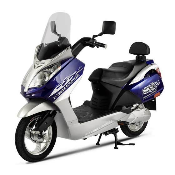
Page 7: Product Features
Product features... -
Page 8: Package Contents
Remove axle from front fork & shipping crate and set aside, do not discard. There are 8 installation steps that must be done prior to using your XB-700Li. Be sure to do them in order and do not skip a step. 1.) FRONT WHEEL AND BRAKE. -
Page 9: 2.) Handlebar Installation
Slide axle thru left fork, then spacer before inserting it into the left side of front wheel. Secure with nut on right side (brake side) and tighten securely 2.) HANDLEBAR INSTALLATION... -
Page 10: Windshield Installation
Locate and remove the handlebar bolt, washer & nut as on previous page.. Remove 4 external screws & 2 internal screws from handlebar front & back black covers for easy installation of handlebar bolt. Slide handlebars over post in the correct position, then insert the bolt &... - Page 11 Image 4 Image 5 Attach the Y Fairing: Insert metal clips onto the back of the “Y” Fairing. (image 6) Attach Fairing headlight/front fairing and secure with the enclosed screws. (image 7 & 8) Be careful not to over tighten! Image 6 Image 7 Image 8...
-
Page 12: Backrest/Pedals/Mirror Installation
4-6.) BACK REST, PEDAL & MIRROR INSTALLATION Install rubber covers over back rest posts. Mount back rest to bike by inserting bolts up thru the bottom (inside trunk) & tighten. Attach left & right foot pedals according to correct side by lining up pedal with bearing on pedal shaft and snap into place. -
Page 13: Battery Connection & Initial Charging Instructions
7.) BATTERY CONNECTION & INITIAL CHARGING Unlock battery box located on the foot plate. Remove battery pack and locate plug. Plug battery wire into battery pack and reinstall pack into foot plate. Lock battery pack in place. Charge the batteries until the light turn’s green indicating that the battery is completely charged. -
Page 14: Product Specification
Product Specifications 1. Wire diagram 2. Specifications Battery Type LiPo4 Battery Voltage 51.2 VDC Motor Wattage 700W Wheel Size 16 inch Top Speed 20 MPH Charging Time 3-4hrs 25 – 35 miles Distance of full charge Battery charging cycles Around 500~700 times Max rider weight 350 Lbs Two rider... -
Page 15: Operation
Operation Your new Electric Bicycle/scooter is a revolutionary new transport product using many lightweight high-powered Lithium batteries and a super high efficiency electric hub motor designed to ASSIST in the propulsion of you and your bicycle. It is important to note the following riding guidelines to ensure you get the best possible experience from your electric bicycle. -
Page 16: Battery Charging & Safety
4) Plug the end of the charger’s cord into the socket of the adaptor first. Next connect the adaptor to the XB-700Li (the charger port in located below the front of the seat). Then plug the chargers’ AC cords into the wall outlet. -
Page 17: Basic Maintenance & Schedule
Maintenance ----Basic 1. There is one 30Amp glass fuse installed in the bike which is located in the battery box. 2. Clean Chain Regularly. 3. Ensure Tires are inflated to 35-40 PSI. 4. Adjust Brake tension via adjusting screws located at Brake lever or on Brake control lever. -
Page 18: Rear Wheel Assembly Instructions
Rear Wheel Assembly Instructions 1. First, remove the two screws that hold the plastic plates on both sides of rear wheel. See figure 1-5: figure 1-5 2. Remove the screw from the end of Brake Cable, and then pull the cable out. See figure 1-6: figure 1-6 3. -
Page 19: Front Wheel Removal Instructions
4. Remove the two nuts on both sides of the rear wheel. See figure 1-9 figure 1-9 5. Slide the wheel forward to allow slack in the chain. 6. Now slide the chain over the rear flywheel and remove the wheel from the bicycle. Front Wheel Removal Instructions 1. -
Page 20: Front Wheel Installation Instructions
Front Wheel Installation Instructions Set your bike on a strong table or workbench to make access easier. Lift the front forks and install the front wheel. Ensure the locking washers are inserted into the holes on the forks. Insert the axle and spacer as shown above (in reverse) Install the two nuts on the end of the axle and tighten. - Page 21 DO NOT RETURN TO STORE! IF YOU NEED HELP CALL TOLL FREE OR GO ONLINE 1-800-772-3852 www.x-tremescooters.com/support/ For General Information or Parts Visit www.x-tremescooters.com...
-
Page 22: How To Guide
How To Adjust Drum Brakes Loosen the brake handle adjustment on handlebars to fully outward. Locate the brake cable adjustment screw and screw this in all the way. Follow your brake cable to the brake caliper. There will be a small nut holding the metal cable to the caliper arm. -
Page 23: How To Replace Controller
How To Replace Controller Remove the Battery Pack from the scooter and set aside until new controller is installed. Open the seat and remove the four (4) seat barrel screws, two (2) near the Latch and two (2)in Front. Remove entire Seat and Seat Barrel from scooter. Unscrew your old controller from the frame - Leave wires connected. -
Page 24: How To Check Brake Safety Switch
Follow wire from throttle housing to white connector and unplug. Loosen small allen head bolt from throttle housing and slide throttle from handlebar. Place new throttle in place and reconnect new connectors. How To Check Brake Safety Switch First remove front fairing and check the throttle connector and brake connectors for loose connection. -
Page 25: How To Test Motor Sensors
Throttle measurement: Leave connector connected while measuring. 3. Locate the throttle connector on the controller, it will be a red connector with 3 wires coming out of it of RED, BLACK & GREEN. Put you Black meter probe in on the black wire. Insert Red probe in on the red wire and turn the scooter in the ON position. -
Page 26: Troubleshooting
While the motor is connected to the controller, powered, and at rest--or, alternatively, powered with +5 volts from a workbench power supply--set up a multi-meter to monitor the sensor's output on one of the 3 wires. Connect the Black Voltmeter Lead to the small black wire by inserting the probe in where the wire goes into the connector. -
Page 27: Throttle Voltage Test
A better test if you have a digital VOM, is to push the probes into the back of the throttle connector at the controller while it is connected. Turn the scooter on, and operate the throttle. You should get near zero to near 4 or 5 volts between the black and third wire (green or yellow). These voltages work for most scooters, but not all. -
Page 28: No Power
1. First pull up battery pack and pull the main power cord out of socket on battery pack to kill all power. 2. Unplug the Large Red and Orange 2 wire connector on controller. This connection is for the Ignition switch test, on the side that has the Red and white wire by looking down inside you will see 2 silver pins and there is a little tab that you push towards the pin and the wire will come out of the connector. -
Page 29: After Fully Charging, Powers Only For Short Distance Use
the test of this is the power light. Does the power light come on when the switch is activated to the On position? Troubleshooting: After Fully Charging, Powers Only For Short Distance Use 1. Suspect the battery charger or the battery as the primary cause of short distance riding after a lengthy or full charge. -
Page 30: Scooter Won't Move
Troubleshooting: Scooter Will Not Move Scooter not moving and Lights do not work using battery, but lights do work when you plug the charger into the side of the scooter and also plug the charger into the wall-Scooter will not move at all and all lights do not work (lights do work when you plug the charger into wall): A) No fuse in fuse assembly= add one of the fuses includes with the scooters B) Bad Fuse= unscrew the cap only on the fuse holder. -
Page 31: Hub Motor Tests
Troubleshooting: Hub Motor Tests With any one of the three sensors disconnected the moped will run very jerky. It may stop but will start again if the throttle is release and then turn. If two or more sensors are disconnected the motor will not start. 3. -
Page 32: Changing Charging Output From 230V To 110V
Motor Winding Test: Test all motor leads from lead to lead. All readings should be .6-.7 ohms. Controller Test: Disconnect all the motor wires from the controller to run these test. Set the volt-meter to read ohms. If your meter does not auto-range set meter to 20K ohms. Check between the red and black power wires. -
Page 33: Bad Brake Switch
Plug the charger into a 110v outlet only and it should have one (1) Red light and (1) Green light. Now plug the charger into the XB-700 socket in addition to the 110v outlet and it should change to two (2) solid Red lights and you will hear the fan turn on. If it is switching colors Red and Green it means your still in the 230v setting. - Page 34 Reconnected main Red wire on controller and security module beeped. Ticking has stopped. D. Checked security system by removing key and hitting left horn to activate security and beeped works as designed. Replaced key to disable the security and beeped. Fix: 1.
-
Page 35: Support
DO NOT RETURN TO STORE! IF YOU NEED HELP CALL OR GO ONLINE 1-253-777-0690 www.x-tremescooters.com/support/ For General Information or Parts Visit www.x-tremescooters.com Revised 04/18/13...
Need help?
Do you have a question about the XB-700Li and is the answer not in the manual?
Questions and answers