Table of Contents
Advertisement
Advertisement
Table of Contents

Related Manuals for ALLEN & HEATH Xone:22


Summary of Contents for ALLEN & HEATH Xone:22
-
Page 1: User Guide
USER GUIDE Publication AP7402... -
Page 2: Warranty
EMC standards. Customers requiring more information about EMC and safety issues can contact Allen & Heath. XONE:22 User Guide AP7402 Issue 1 Copyright © 2009 Allen & Heath Limited. All rights reserved Allen & Heath Limited Kernick Industrial Estate, Penryn, Cornwall, TR10 9LU, UK http://www.allen-heath.com http://www.xone.co.uk... -
Page 3: Packed Items
PACKED ITEMS Check that you have received the following: Xone:22 mixer Spare knobs Power Supply Fit the correct mains adap- tor for your region. Safety Sheet Important ! Read this sheet before starting. Retain for future reference. -
Page 4: Table Of Contents
CONTENTS Congratulations on purchasing the Allen & Heath Xone:22 performance DJ mixer. To ensure that you get the maximum benefit from the unit please spare a few minutes familiarizing yourself with the controls and setup procedures outlined in this user guide. For further information please refer to the additional information available on our web site, or contact our technical support team. -
Page 5: Connection Diagram
CONNECTION DIAGRAM... -
Page 6: Introduction
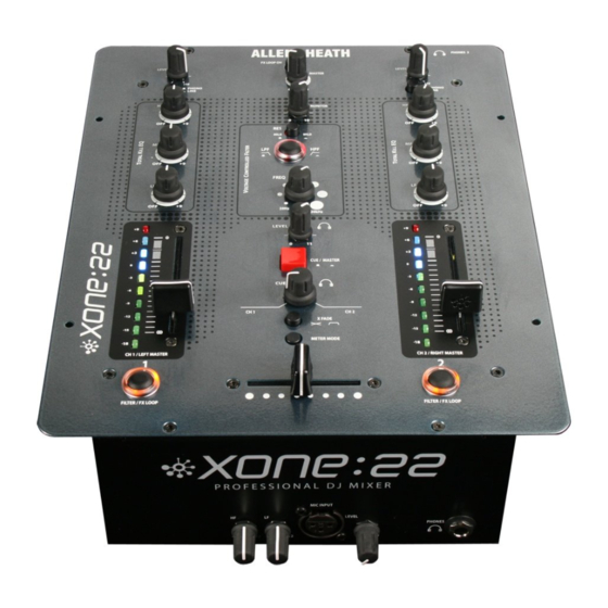
INTRODUCTION TO THE XONE:22 The Xone:22 has been designed to meet the requirements of those users who want a high quality, affordable, compact DJ mixer. Its feature set has been kept to the essential elements needed to produce professional quality mixes, without compromising the design by adding superfluous gimmicks. -
Page 7: Input Channel Controls
INPUT CHANNEL CONTROLS Input level control Adjust so that the aver- age music level lights the 0 LED on the meter, with the beats lighting the +3 to +6 LED. Turn down if the +9 Red LED is illumi- nated Input selector Switches between Phono (turntables) -
Page 8: Master Section Controls
MASTER CONTROLS FX loop on switch Press this switch to activate the external effect loop. Leave switched off if an external effects unit is not connected Master output Level Sets the signal level to the main XLR mix output Monitor output Level Sets the signal level for the local monitor (booth) output Filter Resonance control... -
Page 9: Master Section Controls Continued
MASTER CONTROLS continued Headphone level Sets the level of the head- phone output. Warning! Very high level can cause hearing damage! Cue/Master Switch In the up position (Cue) the headphones will monitor the channel signal before the fad- ers, and the meters will display the pre fade channel signal level. -
Page 10: Rear Panel Connections
Headphone output Rear mini jack output PSU connection Grounding post To prevent damage to your Xone:22 only use Mainly used to con- A&H approved nect the ground wire power supply from some turntables to minimise hum... -
Page 11: Front Panel Connections
FRONT PANEL CONNECTIONS Headphone output Microphone EQ 1/4” jack headphone out- 2 band EQ for adjusting put socket. Use phones the tonal balance of the DJ with a 30 to 70 ohms impedance. Microphone input Microphone Level Professional XLR balanced mic input. Use a low Adjusts the signal level of impedance dynamic hypercardioid Mic for best the mic input. -
Page 12: Filters Reference
FILTER REFERENCE The VCF Filters A voltage controlled filter is an audio filter where the cut-off frequency is altered by a DC control voltage rather than a variable resistor. This produces a much wider operating range and more control over the filter response to create unlimited combinations of tonal effect. -
Page 13: Operating Levels
OPERATING LEVELS It is most important that the system level settings are correctly set. It is well known that many DJs push the level to maximum with meters peaking hard in the belief that they are getting the best from the system. THIS IS NOT THE CASE ! The best can only be achieved if the system levels are set within the normal operating range and not allowed to peak. -
Page 14: Earthing
Do not unbalance the Xone:22 XLR outputs by shorting pin 3 to ground as this may damage the circuitry; for unbalanced operation connect the hot signal to pin 2 and the ground to pin 1. -
Page 15: Servicing And Jumper Settings
Take great care to ensure that no harnesses become trapped and that all connectors are fully pushed home. Replace the screws and test the mixer for correct operation. REMOVE THE SCREWS ARROWED Part number 003-897 Xone:22 Channel fader assy Part number 003-876 Xone:22 Xfader assy To change the Phono input to line Remove the front panel as outlined before. -
Page 16: User Replaceable Spare Parts
The diagram above shows all of the replacement parts that can be ordered from your local technical support, or direct from Allen & Heath, for the Xone:22. When ordering please quote the part number(s) of the required parts - this makes life easier for us! See the previous page for information on replacing the crossfader, and for replacement cross- fader assembly numbers. -
Page 17: Fault Finding
FAULT FINDING No sound from mixer Check that the unit is powered on, and that an audio signal is connected to a channel input. Check that the PHONO/LINE switch is in the correct position for the type of music source connected, (PHONO for turntables, LINE for CD players. -
Page 18: Specification
SPECIFICATIONS Connections Inputs Connection Impedance Nominal Level Maximum Level Phono 47K/330pF 7mV-100mV Line 20K ohm -10 to +18dBu FX RTN 10K ohm 0 to +18dBu <2K ohm -42 TO –12dBu Outputs Main Mix Balanced XLR 68 ohms +4dBu +25dBu Monitor 68 ohms -2dBu +18dBu... -
Page 19: Block Diagram
BLOCK DIAGRAM... -
Page 21: Product Registration
PRODUCT REGISTRATION Registering your product Please go to www.allen-heath.com/register.asp and register your product’s serial number and your details. By registering with us and becoming an official Registered User, you will ensure that any warranty claim you might make is actioned quickly and with the minimum delay. Alternatively, you may either copy or cut off this section of the page, fill in the details, and return it by mail to: Allen &...
Need help?
Do you have a question about the Xone:22 and is the answer not in the manual?
Questions and answers