
Related Manuals for TL Audio M1


Summary of Contents for TL Audio M1
-
Page 1: Table Of Contents
CONTENTS Phase Reverse CONGRATULATIONS! High Pass Filter INTRODUCTION 30dB Pad Block Diagram Equalisation Insertion Points Aux Sends PRECAUTIONS Direct Output INSTALLATION Track Level Control AC Mains Supply Pan Control Audio Connections Mute Switch Mic Inputs PFL Switch Line Inputs Channel Fader Insertion Points Drive and Peak LEDs Direct Output... -
Page 2: Congratulations
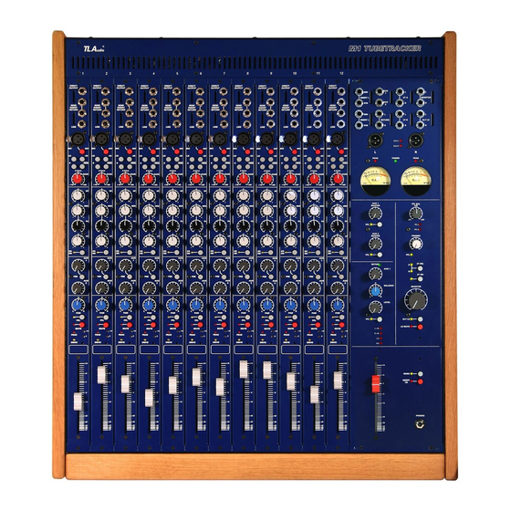
The Ml offers you the TL Audio quality, in a desk that is modular, yet more compact and affordable than the VTC and M4 - and still offers you the same great sound. -
Page 3: Introduction
INTRODUCTION The T L Audio Ml Tube Console combines classic valve techniques with low noise solid state circuitry to construct a mixing console offering high specification signal paths with the unique valve sound quality. 8 or 12 input channels are provided, all with mic and line inputs, switchable 48V phantom power, three band EQ, balanced insertion send and return, 2 Aux sends, Pan and lOOmm Fader. - Page 4 amplifiers on the stereo buss and solid state mix amplifiers on the Aux and PFL busses. The monitoring outputs normally follow the stereo output, but may be switched to the 2 track return inputs, for example to check workstation outputs. Any PFL signal automatically over-rides the monitor output.
-
Page 6: Precautions
PRECAUTIONS As with all electrical equipment, care must be taken to ensure reliable, safe operation of your mixer. The following points should always be observed: All mains wiring should be installed and checked by a qualified electrician, The mixing console is heavy, and may require more than one person to lift and place in position, Ensure the correct operating voltage is selected on the power supply before connecting to the mains supply,... -
Page 7: Installation
AC Mains Supply. The mixer should be placed on a solid, flat surface. Adequate ventilation must be provided, with free space behind the cooling slots in the rear panel and immediately above the ventilation slots along the top of the front panel. Care must be taken to provide appropriate support for the mixer and the cables which will be connected to it. -
Page 8: Audio Connections
Warning: attempted operation on the wrong voltage setting, or with an incorrect fuse, will invalidate the warranty. Audio Connections. Mic Inputs. Balanced inputs: Pin 1 Ground (screen). Pin 2 Signal Phase ("+" or "hot"). Pin 3 Signal Non-Phase ("-" or "cold"). Unbalanced inputs: Pin 1 Ground (screen) -
Page 9: Line Inputs
Line I~put. A 3 pin, 0.25" jack plug is required, which is also compatible with balanced or unbalanced sources, when wired as follows: Balanced inputs: Signal Phase ("+" or "hot"), Ring Signal Non-Phase ("-" or "cold"), Screen Ground. Unbalanced inputs: Signal Phase ("+"... -
Page 10: Direct Output
Direct Output. The Track Output connector is a 3 pin, 0..25" jack socket. The output automatically adjusts for balanced or unbalanced connection. The mating connector should be wired as follows: Balanced outputs: Signal Phase ("+" or "hot"), - Ring Signal Non-Phase ("-" or "cold"), Screen Ground. -
Page 11: Aux Outputs
If an unbalanced output is required, the sleeve and ring should both be connected to ground. Aux Outputs. The Aux outputs are also via balanced, 3 pin jack connectors. The mating connectors should be wired as follows: - Sleeve Ground (screen), - Tip Signal Phase ("+"... -
Page 12: Headphone Outputs
If unbalanced signals are used, the sleeve and ring should both be connected to ground. The right input of the return is norrnalled to the left input, allowing the left input to be used a mono return. Headphone Outputs. The front panel jack socket is suitable for driving headphones of 32 ohms or higher impedance. -
Page 13: Operation
OPERATION Input Selection You must ensure that the correct input connector, mic or line, is being used from the required source. You can select the type of input by pressing the 'LINE' switch at the top right of each channel strip in or out. In the "up' position the mic input is selected; depressing the 'LINE' switch selects the line input as the source. -
Page 14: Phase Reverse
Phase Reverse The phase reverse switch is used to invert the phase of the input signal. It is active on both mic and line inputs. This function could be required when processing a signal that is out of phase with other signals in a mix, in which case the resultant phase error typically appears as a loss of low frequency content, due to cancellation of out of phase components. -
Page 15: Insertion Points
The insert points are configured to be post the input amplifier with its valve stage, but pre EQ and fader. Typical applications include the connection of a compressor (for example the TL Audio 5021) into the channel, or perhaps a dedicated outboard equaliser (e.g. the 5013) for extensive EQ correction or effect. -
Page 16: Mute Switch
Mute Switch The channel may be muted or switched on without affecting the level set on the channel fader. Red LED indicators show which channels are currently muted. PFL Switch When PFL (Pre Fade Listen) is activated a yellow LED illuminates above the button on the channel strip and also in the master section. -
Page 17: Effects Return
Effects Return The stereo effect return is equipped with a rotary control and a UR balance control. The return is fed directly into the stereo mix. A PFL switch allows the return to be auditioned in isolation. A mono signal can be fed to the return by connecting it to the left hand return input only. -
Page 18: Loudspeaker Mute
There is also the optional DO2 card that fits into the back of the master section of the M1 and provides stereo digital output in SPDIF format (RCA Phono connectors). The DO2 has a fixed 24 bit word length, but the sample rate is switchable between 44.1, 48, 88.2 and 96 kHz. -
Page 19: A Final Word
A FINAL WORD We hope you will enjoy your new MI console, we're confident that once you start using it you'll wonder how you managed without one! For best results, switch your MI console on shortly before the start of your session to allow the tubes to fully warm up. -
Page 20: Service
SERVICE Should the mixer or power supply require service, it must be taken or posted to an authorised dealer. Please retain the original packing for possible future use, and ensure the unit is suitably protected during transit. The manufacturer cannot accept responsibility for damage caused during transportation. - Page 21 Ml MIXER TECHNICAL SPECIFICATION. Mic Input: Balanced XLR socket with switchable 48V phantom power, Gain range + 16dB to +60dB with 30dB pad, Frequency response +0, -IdB, 20Hz to 40KHz (at 40dB gain), Input noise (EIN) -128dBu (150 ohm source, 22Hz to 22KHz), Switchable +48V Phantom Power.
-
Page 22: Specifications
L+R Outputs: Balanced insertion points with +4dBu / -IOdBu switch, Stereo Master fader, IOOmm "K" Series, Output via balanced XLR connectors, Noise -76dBu (all channels Line Input @ OdB gain) Maximum level +26dBu. Aux Sends Aux 1 switchable "Pre" fader, Aux 2 post fader, Channel send level controls plus master level with PFL switch, Stereo Return:...
Need help?
Do you have a question about the M1 and is the answer not in the manual?
Questions and answers