Table of Contents
Advertisement
1.
1.1
1.2
1.3
1.4
1.5
2.
2.1
2.2
2.3
2.4
2.5
2.6
2.7
2.8
2.9
3.
3.1
3.2
3.3
3.4
3.5
3.6
3.7
4.
4.1
4.2
4.3
4.4
4.5
4.6
4.7
4.8
4.9
5.
OPERATION SECTION - CONTENTS
2
3
4
5
5
6
7
7
8
8
9
9
9 - 10
10
10
10
11
11
11
11
12
12
12
12 - 13
13
13
13
14
14 - 15
15
15 - 16
16 - 17
18 - 19
20 - 22
23 - 25
26
27
27 - 28
28
28
28 - 29
29
30 - 31
31 - 32
32 - 33
33
34
1
Advertisement
Chapters
Table of Contents

Related Manuals for TL Audio VTC


Summary of Contents for TL Audio VTC
-
Page 1: Table Of Contents
OPERATION SECTION – CONTENTS Introduction. Page Number Input Channel Overview. Master Section Overview. Meterbridge. Options. Precautions. Installation. AC Mains Supply. Mic Inputs. Line Inputs. Insertion Points. Monitor Return Inputs. Tape/Direct Outputs. 9 – 10 Meter Bridge Connection. Group Insertion Points. Group Outputs. -
Page 2: Introduction
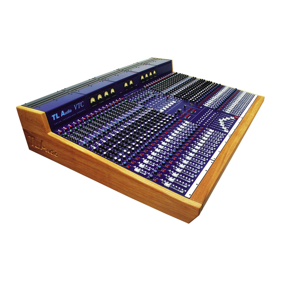
Congratulations on purchasing the TL Audio VTC (Valve Technology Console)! The VTC is a fully modular in-line multitrack mixer that offers all the benefits of the compact 8- buss/multiple tape output format but with the supreme advantage of TL Audio’s critically acclaimed valve circuitry –... -
Page 3: Input Channel Overview
1.1 INPUT CHANNEL OVERVIEW • Uncluttered Channel Preamp section containing a high quality low noise mic amp that combines an SSM 2017 solid state stage with an ECC83/12AX7A secondary valve stage, variable input gain (16 to 60dB), useful 90Hz high pass filter (12dB/octave), and switches for mic/line, phase reverse, and +48v phantom power. -
Page 4: Master Section Overview
Monitor Level control and a PFL trim control with +/-20dB of gain. Two Solo modes are provided on the VTC: PFL or Solo In Place, with a switch in the CR section allowing Solo in Place to be selected. A switch allows the Alternate Loudspeaker outputs to be monitored, and the Control Room output can also be mono’d. -
Page 5: Meterbridge
25 way D-type ribbon connectors. • Fader and Mute automation. The VTC has been designed to allow easy integration of certain third party automation systems, which can be factory fitted prior to shipment if required. -
Page 6: Precautions
1.5 PRECAUTIONS The TL Audio VTC requires a modest amount of installation, and like all electrical equipment, care must be taken to ensure safe, reliable operation. The following points should always be observed: - All mains wiring should be installed and checked by a qualified electrician,... -
Page 7: Installation
2. INSTALLATION 2.1 AC Mains Supply. The mixer includes a separate T L Audio VR1000 power supply, and it is essential that only this supply is used to power the mixer. The power supply is fitted with an internationally approved 3 pin IEC connector. A mating socket with power cord is provided with the unit, wired as follows: Brown: Live. -
Page 8: Mic Inputs
AUDIO CONNECTIONS – CHANNEL 2.2 Mic Inputs. Each channel has a female, 3 pin XLR connector for mic connection. It is compatible with either balanced or unbalanced signals, when the mating connector is appropriately wired: Balanced inputs: - Pin 1 = Ground (screen). - Pin 2 = Signal Phase (“+”... -
Page 9: Insertion Points
2.4 Insertion Points. The insertion points are also interfaced via a 3 pin, 0.25” switched jack socket on the rear of the unit. The pin connections are: - Sleeve = Ground, - Tip = Send, - Ring = Return. The insertion point is unbalanced. If used as an additional send only (e.g. as a send to a tape machine or monitor mixing desk), the Tip and Ring should be wired together, to preserve the signal path through the insertion point. -
Page 10: Meter Bridge Connection
If unbalanced signals are used, the screen and ring should both be connected to ground. 2.7 Meter Bridge Connection The optional bar graph meterbridge is connected to each section of the VTC via these 25 way D-type connectors. See Technical Section 4.17 for more details. -
Page 11: Aux Outputs
2.10 Aux Outputs. The Aux outputs are provided on unbalanced, 2 pin jack connectors. The mating connectors should be wired as follows: - Sleeve = Ground (screen), - Tip = Signal Phase (“+” or “hot”). 2.11 Aux Returns. Six stereo inputs are provided, for effects returns or other line level sources. The connectors are 3 pin jack sockets, and the mating connectors should be wired as follows: - Sleeve = Ground (screen), - Tip... -
Page 12: Master Insertion Points
2.14 Master Insertion Points. The master insertion points are interfaced via a 3 pin, 0.25” switched jack socket on the rear of the unit. The pin connections are: - Sleeve = Ground, - Tip = Send, - Ring = Return. The insertion point is unbalanced. -
Page 13: External Input
Two rear panel sockets are provided, suitable for driving headphones of 32 ohms or higher impedance. A standard 0.25” jack plug should be used. 2.20 Meter Bridge Connection. The optional bar graph meterbridge is connected to each section of the VTC via these 25 way D-type connectors. See Technical Section 4.17 for more details. -
Page 14: Channel Module
Valve Stage LM/HM The microphone pre amp stage is one of the key weaknesses on many consoles but on the VTC it is one of its great strengths. Combining an SSM 2017 solid state stage with an ECC83/12AX7A secondary valve MUTE stage gives the VTC mic pre amp the ideal combination of low noise performance (-127dBu) and rich valve warmth. -
Page 15: Tape Return
+48V mic set-ups. It is ‘pre’ Flip in the signal path so off-tape signals can be LINE phase reversed if required by re-patching through the line input. PHASE GAIN GAIN (4) FLIP The Gain control affects both line or microphone input level, dependent TRIM upon which is selected by the Mic/Line switch. -
Page 16: Insert Point
AUX 3/4 MIX B EQ ON The VTC has a flexible system of auxiliary sends, allowing both the main channel and Mix B signal paths access to pre and post fade sends. Six mono auxiliary sends are accessed via four level controls, and there is a separate stereo send. - Page 17 +48V Used for stereo foldback LINE PHASE GAIN Aux sends 3&4 can be routed to the Master Section’s two headphone mixes (Phones 1&2). Here they can be used exclusively or mixed with other signals, for example auxes 7&8, to create a headphone mix of both FLIP channel and tape monitor signals.
-
Page 18: Eq Section
+48V LINE The VTC has been praised for its classic, ‘musical sounding’ EQ, capable PHASE GAIN of overall contouring, creative shaping and corrective treatments. The EQ stage shares the warmth, transparency and smoothness of the TL Audio’s outboard EQ units. The four band EQ comprises three sections, all within... -
Page 19: Mix B Monitor Section
+48V LINE PHASE GAIN L-MID FLIP TRIM Cut/Boost +/-15dB C e n t r e Frequency 50Hz - STEREO AUX 2kHz EQ ON 0.8 - 7.0 LEVEL (1.25 - 0.15 octaves) MIX B H - MID LM Parametric EQ works in the same way as the HM band. Note the wide overlap of the two bands in the centre frequency range of 500Hz - 2kHz, making the parametric section very useful for creative and corrective manipulation of the many sound sources with energy in the... - Page 20 +48V LINE PAN (16) PHASE GAIN MIX B The Monitor section is labelled ‘Mix B’ FLIP comprises a Pan pot , Mute TRIM MUTE switch, Signal Present and Peak LEDs, a Solo LED, EQ assign switches, Source, Auto and Status switching, and a high quality 60mm SOLO Alps fader.
- Page 21 +48V In practice the red peak light is activated at a level of +18dB or above, LINE allowing some advance warning when bringing up the monitor input PHASE GAIN gain before the headroom limit of +26dB is reached. FLIP SIGNAL PRESENT (19) TRIM This is a green LED which illuminates to show that a signal is present on the monitor channel path when it reaches a level of -30dB.
-
Page 22: Main Channel Output Stage
+48V automation systems Status acts as a momentary switch intended to LINE identify the presence of a signal path to the automation system computer PHASE GAIN - in effect, a ‘local status’ switch. If no automation is fitted then the Status switch has no effect on the audio signal. - Page 23 Solo in Place function is activated elsewhere on the console. All the main channel mute switches are numbered. If an automation system has been installed on the VTC the internal LED will MUTE illuminate to indicate the mute status of its channel.
- Page 24 In effect the group becomes normalised to the tape outputs in a system providing maximum flexibility for an eight group console. This enables all the tracks on a multitrack tape machine to be accessed via the VTC’s...
- Page 25 +48V channel tape outputs without any need for re-patching. LINE PHASE GAIN ROUTING BUTTONS (34) FLIP As previously mentioned (in 27) the pan pot acts as an odd/even signal TRIM feed for the routing matrix. On selection of one of the group routing buttons 1-2, 3-4, 5-6, 7-8, the post fade signal will be sent if panned left to the odd number selected –...
-
Page 26: Master Section
MASTER SECTION AUX MASTERS PHONES 1 LEVEL MUTE MUTE MUTE MUTE MUTE MUTE MUTE C/ROOM MIX B AUX 3/4 AUX 7/8 PHONES PHONES PHONES PHONES PHONES PHONES LEVEL 1kHz 10kHz BALANCE BALANCE BALANCE BALANCE BALANCE BALANCE PHONES 2 MIXB ASSIGN L+ R LEVEL MUTE... -
Page 27: Auxiliary Master Sends
4. MASTER SECTION 4.1 AUXILIARY MASTER SENDS LEVEL At the top of the Master Section are the six mono and single stereo auxiliary send masters. All feature AFL and Mute switches, and a rotary fader which allows complete attenuation through to +15dB of gain, allowing a wide range of effects units to be driven. -
Page 28: Headphone Matrix
PHONES 1 & PHONES 2 The VTC offers a very versatile headphone mix section where stereo foldback can be sourced from any or all of these signals: Control Room, Mix B, Aux 3/4, Aux 7/8 and External. The solo button functions as a PFL, and it is assumed that Aux 3/4 and Aux 7/8 will be used for headphone cue mixes as they are the main pre fade sends. -
Page 29: Talkback Section
Controls the output level of the Mix B signal. Up to +15dB of gain is available on the rotary master fader. This will control the amount of signal fed to both the Mix B outputs and the stereo L/R buss, should the Mix B signal be assigned to it (see below). - Page 30 Five stereo inputs are available on illuminated switches and can be selected individually or in combination: • L + R This routes the main mix left and right outputs (post L+R fader) to the Control Room Monitor. • Mix B This routes the Mix B left and right outputs (post Mix B master level) to the Control Room Monitor.
-
Page 31: Studio Monitor Section
PFL/AFL active is signalled by a red LED adjacent to the active switch, and by the yellow LED on the Master Module VU meter panel. When one or more is selected a signal override will cut in to replace the normal control room output with the dedicated PFL/AFL buss. SOLO IN PLACE When Solo In Place is selected in the Control Room Master Section, SIP replaces the PFL function of Main Channel and Mix B signal paths, but will not affect the Groups, Auxiliary Masters and Stereo... -
Page 32: Group Outputs
Note that if you want to take full advantage of the VTC’s valve capability during track laying, use the Group route to tape as much as possible, thus utilising the extra valve stage in each group mix amp. -
Page 33: Master Left/Right Outputs
monitor their respective group output signals. The group ON switches work in tandem with the group left/right switches above them as indicated by the desk legending. It enables the selected post fade group signal to be sent to the main mix outputs for traditional sub-grouping of signals such as drums and backing vocals. -
Page 34: Specifications
5. SPECIFICATIONS Input Impedance (electronically balanced) Mic input: 2.5 kohms All other inputs: 10kohms minimum Output Impedance All balanced outputs: 100 ohms All unbalanced outputs: 47 ohms Maximum output levels Direct, Group, L/R (balanced): +26dBu L/R (unbalanced): +20dBu Insert sends: +20dBu Maximum Gain Mic input to direct output:... - Page 35 1. Power Supply Distribution. 1.1. Mechanical Construction. The VTC console mechanical construction consists of a number of “bays”, each of which houses 8 input channels, plus a further bay for the Master Section. Each bay operates as a sub-system with its own grounding, PSU Regulators, and balanced audio signal connection between bays.
- Page 36 CAUTION: THE POWER SUPPLY AND CONSOLE CONTAIN HIGH VOLTAGES (UP TO 250V DC) AND HIGH POWER CAPACITY, WITH A RISK OF PERSONAL INJURY AND FIRE. SERVICE SHOULD BE PERFORMED BY COMPETENT QUALIFIED PERSONNEL, IN ACCORDANCE WITH CORRECT ENGINEERING PRACTICE. IF IN ANY DOUBT, REFER SERVICE TO THE RETAILER OR DISTRIBUTOR OF THE CONSOLE.
- Page 37 Note that adjustment of “H+” by RV5 will also cause a change in H-, as the supply is centre tapped to 0V by R20 and R21. As the H- rail is bussed through the desk, some interaction of adjustment between bays may occur if re-adjusted in the console. When on load, some regulation of the heater supply may occur.
-
Page 38: Valve Replacement
Small signal valves such as the twin triodes used in the VTC console are usually very reliable. The valve parameters are not highly critical as local feedback is used to control the circuit performance. -
Page 39: Valve Path Identification
replacement as they age. When replacements do become necessary, they should be obtained from the console supplier. ECC83/12AX7A valves are quite commonly available, but the various manufacturers differ greatly in quality and audio performance, and replacement with the same type as originally supplied with the console will ensure consistency of performance. -
Page 40: Input Bays
3. Input Bays. 3.1. Mechanical Construction. The input modules are carried in a steel cradle which is mounted between the console bulkheads. The cradle provides mounting screw points for the modules, plus two rigid PCB backplanes into which the input modules are plugged. All connections to the input modules are made via a two part DIN41612 connector on each of the backplanes. -
Page 41: Replacing Mute Switches
3.5. Input Circuit Description. The VTC console is a hybrid design, using valve technology where its inclusion is considered to enhance the sound quality of the console. Valve stages are included in the mic/line inputs, the monitor (tape) inputs, and the mix amplifiers for the groups, L+R and Mix B busses. -
Page 42: Equaliser
The monitor input is connected to the balanced input stage, IC5A, and then to the pre-set gain stage, IC4B. The pre-set, RV11, is used to calibrate the module input by matching the monitor gain to the line input 0dB gain. It is only necessary to recalibrate RV11 if the input gain controls RV1 or RV2 have been replaced, and should be performed by feeding a 0dBu signal into the line input, setting the line and monitor gain pots to their centre detent, and noting the level at the insertion send. -
Page 43: Module Fault Finding
automation systems may retain the module fader path - please refer to the automation system installer for details. The Stat (status) switches are also provided for use with certain automation systems only. They are momentary switches intended for identifying a signal path to the automation system computer. The channel and MixB paths may be routed to the equaliser section by switches SW5 and SW6. -
Page 44: Master Module Circuit Description
apparent on various paths. Two valve positions, along with their associated trimmers and IC’s, are intentionally not fitted to PC345. The master front backplane, PC336, is linked to the input bay backplanes, PC337, by short IDC cables carrying the balanced busses. These cables plug into the underside of the PCBs, to avoid fouling the input modules. -
Page 45: Group Outputs
4.4. Group Outputs. Refer to the expanded block diagram, fig 2. The Group mixes and outputs follow a similar path to the L+R outputs described above. The sub-mix for the groups consists of just the Talkback and Oscillator signals, routed onto PC336 as “TAPE +”... -
Page 46: Mixb Outputs
4.5. MixB Outputs. The MixB output signal path is again similar to the L+R outputs described above, except they do not have sub-mixes or insertion points. Refer to the expanded block diagram, fig 4. The mix amplifiers consist of IC9, 10 and 11 on PC336, feeding the valve stages on PC345 via the signals “MIXB L VIN”... -
Page 47: Stereo Returns
CD1347. Following the balanced receiver stages IC2A and IC2B, the return is taken to the balance control, RV3, and buffered by IC4A and IC4B. The sensitivity of the returns is +4dBu by default, but may be changed to -10dBu by fitting jumpers J1 and J2. The stereo returns are controlled by a 60mm fader, followed by a +10dB buffer (IC3A and IC3B), and routed to the L+R sub-mix. -
Page 48: Solo System
foldback mixing from both channel and MixB paths on the input modules. The sources for headphones 1 are mixed by IC2A and IC2B, and then controlled by the level pot RV1. The headphone outputs are directly driven by the high drive TLE2062 at IC1A and IC1B. These devices will directly drive headphones of 32ohms or higher impedance. -
Page 49: Control Room Output
routed via IDC cables and PC355 to the sub-mix on PC349 in the upper Master Module. The sub-mix adds in the locally sourced AFL signals from the Aux Send Masters and Stereo Returns. The signal “PFL L OUT” and “PFL R OUT” are routed back via PC355 to the Control Room and Studio output PCB, PC352, located on the lower Master Module front panel. -
Page 50: External Monitor Inputs
switch inner. Failure to ensure correct alignment may result in the switch cap springing off suddenly if the switch is operated quickly. The push buttons are controlled by similar circuits. For example, the Control Room “L+R” push button, SW2, is debounced by IC1B and toggled by the flip-flop IC2A (see CD1351 sheet 2). The output from IC2A is used to turn on the LED via Q2. -
Page 51: Metering
The external monitoring inputs are routed off PC355 by the IDC cable at CN7, to the Control Room and Studio module, PC352. 4.16. Metering. The console is fitted as standard with retro-style VU meters for the eight groups plus left and right outputs. -
Page 52: Calibration Procedure
5. Calibration Procedure. For the first channel installed: +4dBu 1KHz tone to LINE input, Gain @ 0dB, Channel Fader @ 0dB. BUSS switch off, EQ off. Trim Channel Valve for +4dBu @ DIR OUT. Route to all Groups and L/R. Group and L/R Faders to 0dB. With Channel Pan fully left, trim Group 1/3/5/7 and L Valves for +4dB at their respective OUTPUTS.
Need help?
Do you have a question about the VTC and is the answer not in the manual?
Questions and answers