
Related Manuals for Keithley 2100


Summary of Contents for Keithley 2100
- Page 1 Model 2100 6 1/2-Digit Resolution Digital Multimeter User’s Manual 2100-900-01 Rev. D / September 2011...
- Page 2 All rights reserved. Any unauthorized reproduction, photocopy, or use the information herein, in whole or in part, without the prior written approval of Keithley Instruments, Inc. is strictly prohibited. All Keithley Instruments product names are trademarks or registered trademarks of Keithley Instruments, Inc.
-
Page 3: Safety Precautions
Keithley Instruments products are designed for use with electrical signals that are rated Measurement Category I and Measurement Category II, as described in the International Electrotechnical Commission (IEC) Standard IEC 60664. Most measurement, control, and data I/O signals are Measurement Category I and must not be directly connected to mains voltage or to voltage sources with high transient over-voltages. - Page 4 (note that selected parts should be purchased only through Keithley Instruments to maintain accuracy and functionality of the product). If you are unsure about the applicability of a replacement component, call a Keithley Instruments office for information.
-
Page 5: Table Of Contents
..................1-5 Instruction manual ..................1-5 Repacking for shipment ................1-5 Getting Started ..................2-1 Overview..................... 2-2 Setting up the Model 2100 Digital Multimeter ..........2-2 Adjusting the handle................2-2 Setting the line voltage ................. 2-4 Connecting the power ................2-7 Changing the fuses ................ - Page 6 Table of Contents Model 2100 6 1/2-Digit Resolution Digital Multimeter User’s Manual Set ADC (Auto Zero and Auto Gain) ............ 4-2 Filter ..................... 4-4 Resolution setting (digits) ..............4-6 DC input resistance ................4-7 Threshold resistance (continuity)............4-8 Range (manual and auto)..............
- Page 7 Model 2100 6 1/2-Digit Resolution Digital Multimeter User’s Manual Table of Contents The math operation command ............B-14 The triggering commands..............B-17 The system-related commands ............B-18 Other interface commands ..............B-20 The SCPI status pattern ..............B-20 Status reporting commands..............
- Page 8 Table of Contents Model 2100 6 1/2-Digit Resolution Digital Multimeter User’s Manual This page left blank intentionally. 2100-900-01 Rev. D / September 2011...
-
Page 9: Topic Page
Topic Page Introduction ..................Feature overview ................Specifications ..................Manual addenda ................. Precautions for operation ..............Upkeep of the Model 2100 ..............Safety information ................Safety symbols and terms ............Inspection for damage ................ Shipment contents ................Instruction manual................Repacking for shipment... -
Page 10: Introduction
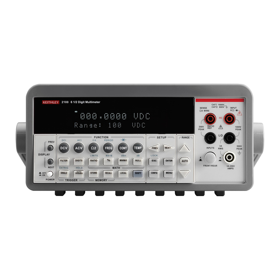
Figure 1-1 The Model 2100 6 1/2-Digit Resolution Digital Multimeter The Keithley Instruments Model 2100 is a rugged and versatile 6 1/2-digit resolution digital multimeter. It has 0.003% one-year basic DC voltage accuracy at 10V range and 0.005% one-year basic resistance accuracy at 10k range. At 6 1/2 digits, the multimeter delivers 50 triggered RDGS/sec via the USB remote interface. -
Page 11: Specifications
If an incorrect display or abnormal beeps occur, you should stop using the equipment at once and contact your local service representative. • Wipe the surface of the Model 2100 multimeter with a dry or damp clean cloth to dust and clean any residue from the enclosure. 2100-900-01 Rev. D / September 2011... -
Page 12: Safety Information
Keithley Instruments service facility if necessary. Safety symbols and terms The following symbols and terms may be found on the Model 2100 or used in this manual. symbol indicates that the user should refer to the operating instructions located in the manual. -
Page 13: Shipment Contents
The latest manual can be downloaded (in PDF format) from the website. Repacking for shipment Should it become necessary to return the Model 2100 for repair, carefully pack the unit in its original packing carton or the equivalent, and follow these instructions: •... - Page 14 Section 1: General Information Model 2100 6 1/2-Digit Resolution Digital Multimeter User’s Manual This page left blank intentionally. Return to Section Topics 2100-900-01 Rev. D / September 2011...
-
Page 15: Getting Started
Section 2 Getting Started In this section: Topic Page Overview ..................... Setting up the Model 2100 Digital Multimeter ........Adjusting the handle ..............Setting the line voltage ..............Connecting the power..............Changing the fuses............... Factory default settings ..............2-18 Model 2100 familiarization .............. -
Page 16: Overview
Setting up the Model 2100 Digital Multimeter The purpose of this section is to prepare you to use the Model 2100 Digital Multimeter (DMM). You should check whether you have all the parts needed to operate your multimeter. All Keithley Instruments products are handled and inspected professionally before shipping out to our customers. - Page 17 TRIGGER MEMORY Adjusting the handle position You can adjust the Model 2100’s handle to suit your needs: Position 1: Default The default position is used for packing the Model 2100 (refer to Figure 2-3). Figure 2-3 Default handle position Position 2: Operating...
-
Page 18: Setting The Line Voltage
Section 2: Getting Started Model 2100 6 1/2-Digit Resolution Digital Multimeter User’s Manual Figure 2-4 Operation handle position Position 3: Carrying The carrying position is shown in Figure 2-5. Figure 2-5 Carrying position Setting the line voltage WARNING Before changing the setting, ensure that the multimeter is disconnected from the AC power. - Page 19 Model 2100 6 1/2-Digit Resolution Digital Multimeter User’s Manual Section 2: Getting Started Figure 2-6 Disconnecting AC power Step 2: Open the voltage setting selector Open the voltage setting selector cap as shown in Figure 2-7 (a flat blade screwdriver may be required).
- Page 20 To accommodate differing local area power requirements, Keithley Instruments has three NOTE available models of voltage setting selectors for the Model 2100 (each with two voltage settings). The voltage setting selector included with your Model 2100 should have the appropriate voltage settings for your area's line power requirements. If you do not have...
-
Page 21: Connecting The Power
Model 2100 6 1/2-Digit Resolution Digital Multimeter User’s Manual Section 2: Getting Started Figure 2-9 Inserting the voltage selector Connecting the power Power-off the multimeter Ensure that the power switch on the front panel is in the "POWER OFF" position before plugging... - Page 22 Model 2100 6 1/2-Digit Resolution Digital Multimeter User’s Manual Figure 2-11 Plugging in the power cord Switch the power on Press the power switch on the front panel to activate the Model 2100 as shown in Figure 2-12. Figure 2-12...
-
Page 23: Changing The Fuses
Verify that the power-line fuse is good and replace it with a new one if it is damaged. The Model 2100 is shipped from the factory with a 0.25A/250V, 5×20mm slow-blow glass fuse installed (Keithley Instruments part number FU-96-4). This is the correct fuse type for all line voltage settings;... - Page 24 Section 2: Getting Started Model 2100 6 1/2-Digit Resolution Digital Multimeter User’s Manual Figure 2-13 Disconnecting the AC power Step 2: Open the voltage setting selector Open the voltage setting selector cap as shown in Figure 2-14 (you will need a screwdriver to do so).
- Page 25 Model 2100 6 1/2-Digit Resolution Digital Multimeter User’s Manual Section 2: Getting Started Figure 2-15 Removing the red voltage setting selector Step 4: Remove the damaged power line fuse Remove the damaged fuse from the selector as shown in Figure 2-16.
- Page 26 Section 2: Getting Started Model 2100 6 1/2-Digit Resolution Digital Multimeter User’s Manual Figure 2-17 Replacing the fuse Step 6: Reinsert the voltage selector Insert the voltage setting selector back into the socket and close the cap as shown in Figure 2-18.
- Page 27 Current protection using 3A and 7A current input fuses in series The two main fuses located in the front and rear current input terminals of your Model 2100 are 3A, 250V, 5x20mm fast-acting glass fuses (Keithley Instruments part number FU-99-1). The additional current input fuse is a 7A, 250V, 5x20mm fast-acting ceramic tube fuse.
- Page 28 Section 2: Getting Started Model 2100 6 1/2-Digit Resolution Digital Multimeter User’s Manual Step 1: Disconnect the AC power Verify that the meter is disconnected from AC power, as shown in Figure 2-20. Figure 2-20 Disconnecting the AC power Step 2: Release the current input terminal fuse holder...
- Page 29 Model 2100 6 1/2-Digit Resolution Digital Multimeter User’s Manual Section 2: Getting Started Figure 2-22 Removing the current input terminal fuse holder Step 4: Remove and replace the damaged fuse Remove the damaged fuse and replace it with the same type and rating of fuse (see Figure 2-23).
- Page 30 Section 2: Getting Started Model 2100 6 1/2-Digit Resolution Digital Multimeter User’s Manual Figure 2-24 Reinserting and securing the current input terminal fuse holder WARNING Before reconnecting the power line cord to your multimeter, make sure that the power switch is in the "POWER OFF" position.
- Page 31 Model 2100 6 1/2-Digit Resolution Digital Multimeter User’s Manual Section 2: Getting Started Figure 2-26 Releasing the 7A current input fuse holder on the rear panel Step 3: Remove the current input terminal fuse holder Gently pull out the current input terminal fuse holder to expose the 7A current input...
-
Page 32: Factory Default Settings
Section 2: Getting Started Model 2100 6 1/2-Digit Resolution Digital Multimeter User’s Manual Figure 2-28 Removing and replacing the damaged fuse Step 5: Reinsert and secure the 7A current input terminal fuse holder Reinsert the 7A current input terminal fuse holder, turning it to the right as you push it in (see Figure 2-29). -
Page 33: Model 2100 Familiarization
Input Resistance 10M Model 2100 familiarization The Model 2100 6 1/2-Digit Resolution Digital Multimeter consists of three major parts: the front panel, the display, and the rear panel. Following is a discussion of these components. The front panel The keys and terminals on the front panel are divided into the following groups (refer to ... - Page 34 Section 2: Getting Started Model 2100 6 1/2-Digit Resolution Digital Multimeter User’s Manual Figure 2-30 Front panel keys and terminals 1000V 600V INPUT SENSE 4 WIRE RATIO 200V 1000V PEA K PEA K FUNCTION SETUP RANGE PERIOD PREV 500V AC V...
-
Page 35: The Display
(maximum current: 3A, 250V) The display The Model 2100 has a 5x7 character dot-matrix, dual-line display with three-color (white, red, and yellow) annunciators for easy viewing. There are two rows in the dual-display screen. The upper row displays both readings and measurement units. A maximum of 13 characters is possible for the upper row dot-matrix display. - Page 36 Section 2: Getting Started Model 2100 6 1/2-Digit Resolution Digital Multimeter User’s Manual for the lower row dot-matrix display. There are additional annunciators above and on the right side of the display screen that indicate the state or condition of an ongoing measurement. They are explained individually in the following sections.
-
Page 37: The Rear Panel
OFF: Indicates the front panel display is turned off Figure 2-33 Annunciators on the right The rear panel The rear panel of the Model 2100 is shown in Figure 2-34. This figure includes important abbreviated information that should be reviewed before using the instrument. - Page 38 Section 2: Getting Started Model 2100 6 1/2-Digit Resolution Digital Multimeter User’s Manual a. Contains the AC line receptacle, power line fuse, and line voltage setting • Configured for line voltages of 120/220V or 120/240V (depending on the power utility in your area)
-
Page 39: Basic Measurement Functions
Section 3 Basic Measurement Functions In this section: Topic Page Introduction ..................Voltage measurements (DC and AC)..........How to measure voltage ............... Current measurements (DC and AC)..........How to measure current ............... Resistance measurements (2- and 4-wire) ......... How to measure resistance ............ -
Page 40: Introduction
Voltage measurements (DC and AC) The ranges for DC voltage (DCV) measurements for the Model 2100 are 100mV, 1V, 10V, 100V, and 1000V. For AC voltage (ACV) measurements, the ranges are 100mV to 750V RMS, or 1000V peak. -
Page 41: How To Measure Voltage
Current measurements (DC and AC) The ranges for DC current measurements for the Model 2100 are 10mA, 100mA, 1A, and 3A, with a sensitivity of 10NA. For AC current measurements, the range is 1A to 3A RMS with a sensitivity ... -
Page 42: Resistance Measurements (2- And 4-Wire)
Section 3: Basic Measurement Functions Model 2100 6 1/2-Digit Resolution Digital Multimeter User’s Manual Figure 3-4 Model 2100 current measurement (front panel) 1000V 600V INPUT SENSE 4 WIRE RATIO 200V 1000V PEA K PEA K FUNCTION SETUP RANGE PERIOD PREV... - Page 43 Model 2100 6 1/2-Digit Resolution Digital Multimeter User’s Manual Section 3: Basic Measurement Functions Figure 3-6 Model 2100 2-wire resistance 1000V 600V INPUT SENSE 4 WIRE RATIO 200V 1000V PEA K PEA K Ω2 resistance FUNCTION SETUP RANGE PERIOD under test...
-
Page 44: How To Measure Resistance
("OVLD") will be displayed. Frequency and period measurements The Model 2100 uses an on-board counter with 25MHz to measure the frequency (period). The measurement band is from 3Hz to 300kHz (or 333ms to 3.3 s), and the measurement voltages range from 100mV to 750V in AC. -
Page 45: Continuity Measurements
Diode measurements The Model 2100 uses a current source of 1mA for diode testing. The maximum resolution is 10 on a fixed range of 1VDC. The default threshold voltage is fixed between 0.3V and 0.8V and the reading rate is fixed at 0.1PLC (the voltage band is adjustable from 0.01V up to 1.2V). The meter will beep when the diode measured value is in range. -
Page 46: How To Measure A Diode
Section 3: Basic Measurement Functions Model 2100 6 1/2-Digit Resolution Digital Multimeter User’s Manual WARNING The positive end of the source signal must be connected to the HI input terminals, and the negative end to the LO input terminals. How to measure a diode Select input signal connections on the front or rear panel. -
Page 47: 3-Wire Rtd Measurements
Model 2100 6 1/2-Digit Resolution Digital Multimeter User’s Manual Section 3: Basic Measurement Functions Figure 3-12 Theory diagram of 2-wire RTD measurement 1000V 600V INPUT SENSE 4 WIRE Input HI RATIO 200V 1000V PEA K PEA K FUNCTION SETUP RANGE... -
Page 48: 4-Wire Rtd Measurements
Section 3: Basic Measurement Functions Model 2100 6 1/2-Digit Resolution Digital Multimeter User’s Manual c) Using the PREV and NEXT keys, select the SENSOR. d) Press ENTER. Select USER RTD and press ENTER. Select R-ZERO and press ENTER. Enter in the sum of the zero RTD resistance plus the resistance of the third wire measured in step two (e.g., 100 Ohms plus 0.05 Ohms = 100.05 Ohms). -
Page 49: Front Panel Operations
Section 4 Front Panel Operations In this section: Topic Page Introduction ..................Measurement configuration ..............Set ADC (Auto Zero and Auto Gain) ..........Filter....................Resolution setting (digits) ............. DC input resistance ..............Threshold resistance (continuity)..........Range (manual and auto) ............. Rate (integration time) .............. -
Page 50: Introduction
The Auto Zero and Auto Gain functions are used to minimize offset influence on your measurements. When Auto Zero or Auto Gain is enabled, the Model 2100 takes the input signal reading as a base value and then internally disconnects the input signal, taking an offset reading (a null offset). - Page 51 Model 2100 6 1/2-Digit Resolution Digital Multimeter User’s Manual Section 4: Front Panel Operations Table 4-1 Relationship of resolution to Auto Gain Resolution Auto Zero Auto Gain Integration time (PLC) Fast 4 1/2 digits 0.02 Slow 4 1/2 digits Fast 5 1/2 digits...
-
Page 52: Filter
Model 2100 6 1/2-Digit Resolution Digital Multimeter User’s Manual Filter Filter is used to remove noises in measurement readings. The Model 2100 is equipped with two types of filters: an AC filter and a digital filter. The AC filter is used for AC measurements only, and affects the speed measurement reading. - Page 53 Digital filter Definition The Model 2100 uses an averaging digital filter to yield a reading from 2 to 100 past measurement readings (past measurement readings are stored in stack memory). You can select one of two modes of digital filter operation: Moving Average mode or Repeating Average mode.
-
Page 54: Resolution Setting (Digits)
Resolution setting (digits) Definition Resolution is the number of digits a multimeter can measure. Using the Model 2100 multimeter, you can select the resolution for a specific measurement. The choices for the resolution setting are: fast 4 1/2, slow 4 1/2, fast 5 1/2, slow 5 1/2, fast 6 1/2, and slow 6 1/2. For higher measurement accuracy, select 6 1/2-digit resolution;... -
Page 55: Dc Input Resistance
DC input resistance Definition To reduce the effect of loading errors due to the input resistance, the Model 2100 allows you to select a much larger input resistance (> 10G ) for low input DC voltage (100mV, 1V, and 10V) 2100-900-01 Rev. -
Page 56: Threshold Resistance (Continuity)
Section 4: Front Panel Operations Model 2100 6 1/2-Digit Resolution Digital Multimeter User’s Manual measurements. This feature is only available for DC voltage measurements and is not applicable to other measurement functions. Default The default input resistance for all measurements is 10M (refer to Table 2-2). -
Page 57: Range (Manual And Auto)
120% and the minimum is 10%. Default The default range setting for the Model 2100 is auto-range. The user-selected range is stored in volatile memory and the default will be restored when the meter is turned off (refer to Table 2-2 the factory default range). -
Page 58: Rate (Integration Time)
The unit of the integration time is in PLC (power line cycles); one PLC for 60Hz is 16.67ms, and for 50Hz is 20ms. The Model 2100 has four different integration times you can select: 0.02 PLC, 0.1 PLC, 1 PLC, and 10 PLC. -
Page 59: Sensor Selection For Temperature
Model 2100 6 1/2-Digit Resolution Digital Multimeter User’s Manual Section 4: Front Panel Operations CONFigure:< function> <range>, <resolution> MEASure:< function>? <range>, <resolution> SENSe:< function>:RESolution <resolution> To set the integration time through a remote interface, use the following commands: SENSe:VOLTage:DC:NPLCycles {0.02|0.1|1|10|MINimum|MAXimum}... - Page 60 Section 4: Front Panel Operations Model 2100 6 1/2-Digit Resolution Digital Multimeter User’s Manual When 0°C < t < 630 °C: 1+At+Bt When 0°C < t < 630 °C: 1+At+Bt Where: A = B = - • 10 B = -...
-
Page 61: Input Terminal Switch
SENSe:TEMPerature:SPRTD:DX {<value>|MINimum|MAXimum} Input terminal switch Definition This Model 2100 has five input terminals on both the front and rear terminals for taking measurements. When the rear input is selected, the REAR annunciator is shown on the front panel display. Default The default setting is the front terminals. -
Page 62: Trigger Operations
In this section, we will discuss the triggering system in the Model 2100 multimeter. The Model 2100 provides a variety of trigger operations. You can select a trigger mode, a trigger source, and different trigger settings for specific measurements. Your selection is stored in volatile memory and the default settings will be restored after power is turned-off. - Page 63 Model 2100 6 1/2-Digit Resolution Digital Multimeter User’s Manual Section 4: Front Panel Operations Figure 4-9 Toggle auto triggering on and off 1000V 600V INPUT SENSE 4 WIRE RATIO 200V 1000V PEA K PEA K AUTO TRIGGER FUNCTION SETUP RANGE...
-
Page 64: Trigger Source
External Triger Terminal You can trigger the Model 2100 by using a low-true pulse to the Ext Trig (external trigger) terminal located on the rear panel. And to use this terminal via the remote interface, you have to select the external trigger source by using the TRIGer:SOURce EXTernal command. - Page 65 Model 2100 6 1/2-Digit Resolution Digital Multimeter User’s Manual Section 4: Front Panel Operations Figure 4-11 Ext Trigger input VM COMP (Voltmeter Complete) Terminal The rear panel VM COMP terminal provides a low-true pulse after finishing each measurement. The VM COMP and external trigger shown below provides a standard hardware handshake...
-
Page 66: Trigger Setting
Model 2100 6 1/2-Digit Resolution Digital Multimeter User’s Manual Trigger setting You can specify a variety of trigger settings on the Model 2100, including the number of samples per trigger, the number of triggers per event, reading hold, and the trigger delay for your measurements. -
Page 67: Reading Hold
The default setting for trigger delay is automatically applied if you do not specify a delay value. The Model 2100 will automatically select a delay time based on the measurement settings. A list of the default settings for each measurement function is shown in Table 4-3. -
Page 68: Math Operations
TRIGger:DELay {<seconds>|MINimum|MAXimum} TRIGger:DELay:AUTO {OFF|ON} Math operations The Model 2100 Digital Multimeter can perform eight math operations: RATIO, %, Min/Max, NULL, Limits, MX+B, dB, and dBm testing. Data from measurements taken are either stored for later use, 4-20 Return to Section Topics 2100-900-01 Rev. -
Page 69: Ratio
Model 2100 6 1/2-Digit Resolution Digital Multimeter User’s Manual Section 4: Front Panel Operations or used to perform mathematical operations on the readings. Note that these math operations are available to all measurement functions except continuity and diode testing. The "MATH" annunciator on the display indicates the state of a mathematical feature and NOTE will be lit when any math feature (excluding Ratio) is enabled. -
Page 70: (Percent)
Section 4: Front Panel Operations Model 2100 6 1/2-Digit Resolution Digital Multimeter User’s Manual To make a ratio measurement using a remote interface: Use the following command to make a Ratio measurement: CONFigure:VOLTage:DC:RATio{<range>|MIN|MAX|DEF},{<resolution>|MIN|MAX|DEF} % (Percent) Definition This mathematical function calculates the ratio of a measurement reading to a specified target value in the form of a percentage. -
Page 71: Min/Max
Model 2100 6 1/2-Digit Resolution Digital Multimeter User’s Manual Section 4: Front Panel Operations CALCulate:FUNCtion PERCent CALCulate:STATe {OFF|ON} CALCulate:STATe? CALCulate:PERCent:TARGet{<value>|MINimum|MAXimum} CALCulate:PERCent:TARGet? [MINimum|MAXimum MIN/MAX Definition: When the MIN/MAX function is enabled, the multimeter takes in a series of readings from the measurements, stores the minimum and maximum readings in memory, and then calculates the average value of all readings. -
Page 72: Null
Section 4: Front Panel Operations Model 2100 6 1/2-Digit Resolution Digital Multimeter User’s Manual CALCulate:FUNCtion AVERage CALCulate:STATe {OFF|ON} CALCulate:STATe? CALCulate:AVERage:MINimum? CALCulate:AVERage:MAXimum? CALCulate:AVERage:AVERage? CALCulate:AVERage:COUNt? Null Definition When the Null function is enabled, the displayed measurement reading is the difference between the measured input signal reading and the stored null (also called relative) value. The null (relative) value is stored in volatile memory, which will be cleared when the multimeter is shut off. -
Page 73: Limits Test
Model 2100 6 1/2-Digit Resolution Digital Multimeter User’s Manual Section 4: Front Panel Operations Figure 4-19 Using the NULL function from the front panel 1000V 600V INPUT SENSE NULL CONFIG 4 WIRE RATIO 200V 1000V PEA K PEA K PREV... -
Page 74: Mx+B
Section 4: Front Panel Operations Model 2100 6 1/2-Digit Resolution Digital Multimeter User’s Manual Figure 4-20 Configuring the Limits function from the front panel 1000V 600V INPUT SENSE 4 WIRE RATIO SHIFT CONFIG RATIO 200V 1000V PEA K PEA K... - Page 75 Model 2100 6 1/2-Digit Resolution Digital Multimeter User’s Manual Section 4: Front Panel Operations This mathematical function multiplies a measurement reading (X) by a specified scale factor (M), and adds an offset (B) automatically. The answer (Y) will then be shown on the display according...
- Page 76 Section 4: Front Panel Operations Model 2100 6 1/2-Digit Resolution Digital Multimeter User’s Manual The dB feature takes a DC or AC voltage measurement and displays it in decibel units that correspond with a relative reference value. The calculation of dB is listed below:...
-
Page 77: Dbm
With dBm selected, a voltage measurement is displayed as the level of power (relative to 1 milliwatt) dissipated through a reference resistance. The reference resistance is adjustable in the Model 2100 Digital Multimeter. The calculation of dBm is defined as below: dBm = 10 x log(V )/1mW Vin is the input signal voltage;... - Page 78 Section 4: Front Panel Operations Model 2100 6 1/2-Digit Resolution Digital Multimeter User’s Manual Figure 4-25 Setting the reference resistance from the front panel 1000V 600V INPUT SENSE SHIFT 4 WIRE MIN/MA X CONFIG RATIO 200V 1000V PREV NEXT PEA K...
-
Page 79: Other System-Related Operations
Display Definition The Model 2100 Digital Multimeter has a 5x7 dot-matrix, dual display with three-color (white, red and yellow) annunciators for better viewing. A maximum of 13 characters are allowed for upper row dot-matrix display, and a maximum 16 characters are allowed for lower row dot-matrix display... -
Page 80: Beeper
Beeper Definition The Model 2100 Digital Multimeter beeps when certain conditions are met or when an error occurs. When you don't want the beeper to sound, you can disable it. Although you can turn off the beeper, the click sound you hear when a key is pressed will not be disabled. The beeper state is stored in volatile memory, and the default will be restored when the meter has been turned-off or after a remote interface reset. -
Page 81: Reading Memory (Store And Recall)
Using the reading memory You can store readings and access those readings through either the front panel or a remote interface. Readings stored from the Model 2100 to a remote interface will be stored in first-in- first- NOTE out order. - Page 82 Section 4: Front Panel Operations Model 2100 6 1/2-Digit Resolution Digital Multimeter User’s Manual Use PREV and NEXT keys to move between the digits and up and down arrow keys to increase or decrease numbers as desired. When ready, press ENTER (the default number of readings will be restored when the meter has been turned off).
-
Page 83: Sensitivity Band (Hold)
Initial mode has two settings: DEFAULT and SAVE DATA. You can select SAVE DATA to save the current configuration, or select DEFAULT to restore the factory default configuration after restarting the Model 2100. The valid ranges for SAVE DATA are listed in Table 4-5. -
Page 84: Language
POWER TRIGGER MEMORY Language The Model 2100 Digital Multimeter supports two languages: Default and A34401. To select a language: Press the MENU key, and use the PREV and NEXT keys to select the SYSTEM submenu. Press ENTER, then use the PREV and NEXT keys to select the LANGUAGE submenu. -
Page 85: Error Condition
Model 2100 6 1/2-Digit Resolution Digital Multimeter User’s Manual Section 4: Front Panel Operations Figure 4-34 Selecting a language 1000V 600V INPUT SENSE 4 WIRE MENU RATIO 200V 1000V PEA K PEA K PREV NEXT FUNCTION SETUP RANGE PERIOD PREV... -
Page 86: Firmware Revision
Occasionally, updated firmware for the Model 2100 is released. The Product Information CD-ROM that came with your Model 2100 contains the latest firmware revision available at the time of shipping; you can also download the latest version of the firmware from the Keithley Instruments website, www.keithley.com. - Page 87 Connect your Model 2100 to your computer with the included USB cable. Insert the Product Information CD-ROM that came with your Model 2100 into the CD drive of your computer (or navigate to the files you downloaded from the Keithley Instruments website) and double-click the DmmUpdate.exe file to begin the installation of the Model...
- Page 88 The Open dialog box Highlight the 5407_xx.xx.bin file and click Open (see Figure 4-38) to start the DSP firmware version update. The 2100 (USBTMC) Update Version window will display a "Please wait" message while the file is executing, as shown in Figure 4-39.
-
Page 89: Calibration
To confirm the update has been properly completed, check the firmware revision number (see check the firmware revision). Calibration The Model 2100 will show the latest calibrated date and the next calibration date on the display after following the operation below (refer to Figure 4-41 for the location of the keys used). - Page 90 How to execute Self-test You can execute a complete self-test by using the front panel operation. This test procedure provides more tests for the hardware of the Model 2100 than the power-on tests. Refer to Figure 4- for assistance and follow the procedure below to perform the complete self-test.
- Page 91 Model 2100 6 1/2-Digit Resolution Digital Multimeter User’s Manual Section 4: Front Panel Operations 608 Buffer2 offset out of range: This procedure is to test the offset of buffer U508. The result is checked against a limit of 0 ± 0.1mV.
- Page 92 Section 4: Front Panel Operations Model 2100 6 1/2-Digit Resolution Digital Multimeter User’s Manual 624 Unable to sense line frequency: The supplied voltage AC2 is routed through a comparator U4 to generate a logic input signal. This test checks that the logic input from U4 to panel MCU U3 is toggling.
-
Page 93: Remote Interface Operations
Section 5 Remote Interface Operations In this section: Topic Page Introduction ..................Pass/fail output from the USB connector........Setting up the remote interface............Remote interface commands .............. Common commands ..............Other measurement configuration commands ......Math operation commands ............Triggering .................... -
Page 94: Introduction
Pass/fail output from the USB connector The USB connector on the rear panel of the Model 2100 is a series "B" connector. When the USB interface is disabled, the internal pass and fail TTL output signals (limit testing) will be connected to the USB connector. -
Page 95: Remote Interface Commands
• Agilent I/O Library Suite 14.2 or greater (the Keithley I/O Layer 5.0 is included on the CD-ROM that came with your Model 2100) On the CD-ROM that came with your Model 2100, double-click the 2100.exe file to start the software installation. - Page 96 Section 5: Remote Interface Operations Model 2100 6 1/2-Digit Resolution Digital Multimeter User’s Manual FRESistance? {<range>|MIN|MAX|DEF},{<resolution>|MIN|MAX|DEF} FREQuency? {<range>|MIN|MAX|DEF},{<resolution>|MIN|MAX|DEF} PERiod? {<range>|MIN|MAX|DEF},{<resolution>|MIN|MAX|DEF} CONTinuity? DIODe? TEMPerature? CONFigure: Definition The CONFigure command offers a little more flexibility than the MEASure? command. The multimeter sets the parameters for the requested function, range and resolution, but does not make the measurements.
- Page 97 Model 2100 6 1/2-Digit Resolution Digital Multimeter User’s Manual Section 5: Remote Interface Operations The FETCh? command sends the data in the multimeter's internal memory to the output buffer, where you can read them into your bus controller. SENSe Definition The SENSe subsystem is used to configure and control the measurement functions.
- Page 98 Section 5: Remote Interface Operations Model 2100 6 1/2-Digit Resolution Digital Multimeter User’s Manual FREQuency:VOLTage:RANGe:AUTO? PERiod:VOLTage:RANGe:AUTO {OFF| PERiod:VOLTage:RANGe:AUTO? [SENSe:] VOLTage:DC:RESolution {<resolution>|MINimum|MAXimum} VOLTage:DC:RESolution? [MINimum|MAXimum] VOLTage:AC:RESolution {<resolution>|MINimum|MAXimum} VOLTage:AC:RESolution? [MINimum|MAXimum] CURRent:DC:RESolution {<resolution>|MINimum|MAXimum} CURRent:DC:RESolution? [MINimum|MAXimum] CURRent:AC:RESolution {<resolution>|MINimum|MAXimum} CURRent:AC:RESolution? [MINimum|MAXimum] RESistance:RESolution {<resolution>|MINimum|MAXimum} RESistance:RESolution? [MINimum|MAXimum] FRESistance:RESolution {<resolution>|MINimum|MAXimum}...
-
Page 99: Other Measurement Configuration Commands
Model 2100 6 1/2-Digit Resolution Digital Multimeter User’s Manual Section 5: Remote Interface Operations [SENSe:] FREQuency:APERture {0.01|0.1|1|MINimum|MAXimum} FREQuency:APERture? [MINimum|MAXimum] PERiod:APERture {0.01|0.1|1|MINimum|MAXimum} PERiod:APERture? [MINimum|MAXimum] [SENSe:] DETector:BANDwidth {3|20|200|MINimum|MAXimum} DETector:BANDwidth? [MINimum|MAXimum] [SENSe:] AVERage:TCONtrol {MOVing|REPeat} AVERage:TCONtrol? AVERage:COUNt {<value>|MINimum|MAXimum} AVERage:COUNt? [MINimum|MAXimum] AVERage:STATe {OFF| AVERage:STATe? [SENSe:]... -
Page 100: Triggering
DATA:FEED RDG_STORE,{"CALCulate"|""} DATA:FEED? Triggering The Model 2100 Digital Multimeter provides a variety of trigger operations: you can select a trigger mode, a trigger source, and different trigger settings for individual measurements. Refer to Figure for a trigger operation flow chart. -
Page 101: System-Related Commands
Model 2100 6 1/2-Digit Resolution Digital Multimeter User’s Manual Section 5: Remote Interface Operations [TRIGger:] SOURce {BUS|IMMediate|EXTernal} SOURce? TRIGger: DELay {<seconds>|MINimum|MAXimum} DELay? [MINimum|MAXimum] [TRIGger:] DELay:AUTO {OFF|ON} DELay:AUTO? [SAMPle:] COUNt {<value>| MINimum|MAXimum } COUNt? [MINmum|MAXimum ] [TRIGger:] COUNt {<value>| MINimum|MAXimum|INFinite }... -
Page 102: Other Interface Commands
Section 5: Remote Interface Operations Model 2100 6 1/2-Digit Resolution Digital Multimeter User’s Manual STATus:PRESet *CLS *ESE <enable value> *ESE? *ESR? *OPC *OPC? *PSC {0| } *PSC? *SRE <enable value> *SRE? *STB? Other interface commands SYSTem:LOCal SYSTem:REMote IEEE-488.2 common commands *CLS *ESE <enable value>... -
Page 103: Error Messages
Section 6 Error Messages In this section: Topic Page Introduction ..................Execution errors .................. Self-test errors .................. -
Page 104: Introduction
Model 2100 6 1/2-Digit Resolution Digital Multimeter User’s Manual Introduction Errors are retrieved from the Keithley Instruments Model 2100 6 1/2-Digit Resolution Digital Multimeter in first-in-first-out (FIFO) order. The first error returned is the first error that was stored. When you have read all errors from the queue, the “ERROR” annunciator turns off. The Model 2100 beeps once each time an error occurs. - Page 105 Model 2100 6 1/2-Digit Resolution Digital Multimeter User’s Manual Section 6: Error Messages Table 6-1 (continued) Execution error codes Error code Description - 151 Invalid string data An invalid character string was received. - 158 String data not allowed A character string was received but not allowed for the command.
-
Page 106: Self-Test Errors
Section 6: Error Messages Model 2100 6 1/2-Digit Resolution Digital Multimeter User’s Manual Table 6-1 (continued) Execution error codes Error code Description 531 Insufficient memory There is not enough memory to store the requested number of readings in INITiate internal memory using the command. -
Page 107: Specifications
Appendix A Specifications In this appendix Topic Page Specifications .................. - Page 108 Input bias current <30pA at 25 °C. c. Input protection 1000V all ranges (2-W input). d. Measurement rate set to 1 PLC. Specifications are subject to change without notice. SPEC-2100 Rev. C / Sep 2011 Page 1 of 4...
- Page 109 Max lead resistance 10% of range per lead for 100Ω and 1kΩ ranges; add 1kΩ per lead for all other ranges. For 1kΩ unbalance in LO lead. For line frequency ± 0.1%. Excluding probe errors. 23°C ±5°C. Specifications are subject to change without notice. Page 2 of 4 SPEC-2100 Rev. C / Sep 2011...
- Page 110 Slow ac filter (3Hz bandwidth). b. Pure sine wave input greater than 5% of range. 750Vac range is limited to 100kHz. 750Vac range is limited to 100kHz. Specifications are subject to change without notice. SPEC-2100 Rev. C / Sep 2011 Page 3 of 4...
- Page 111 The LO jack is marked with 500Vpk against ground and SENSE HI to LO is only marked with 200Vpk, in opposition to the label of 600V CAT II and/or 1000V CAT I against ground and IEC 61010-1. Specifications are subject to change without notice. Page 4 of 4 SPEC-2100 Rev. C / Sep 2011...
- Page 112 Appendix A: Specifications Model 2100 6 1/2-Digit Resolution Digital Multimeter User’s Manual This page left blank intentionally. Section Topics Return to 2100-900-01 Rev. D / September 2011...
-
Page 113: Remote Interface Reference
Other interface commands B-20 ............The SCPI status pattern B-20 ............Status reporting commands B-26 ............. Model 2100-specific SCPI compliance information B-28 ..... IEEE-488 compliance information B-30 .......... About application programs B-30 ............Visual Basic 6 programming example 1: MEASure.bas B-30 .. - Page 114 Appendix B: Remote Interface Reference Model 2100 6 1/2-Digit Resolution Digital Multimeter User’s Manual An introduction to SCPI language SCPI (Standard Commands for Programmable Instruments) is an ASCII-based instrument command language designed for test and measurement instruments. SCPI commands are based on a hierarchical structure, also known as a tree system. In this system, associated commands are grouped together under a common node or root, thus forming subsystems.
- Page 115 Model 2100 6 1/2-Digit Resolution Digital Multimeter User’s Manual Appendix B: Remote Interface Reference The command syntax shows most commands (and some parameters) as a mixture of upper and lowercase letters. The uppercase letters indicate the abbreviated spelling for the command. For shorter program lines, send the abbreviated form.
-
Page 116: Scpi Parameter Types
Appendix B: Remote Interface Reference Model 2100 6 1/2-Digit Resolution Digital Multimeter User’s Manual If you send two query commands without reading the response from the first, and then NOTE attempt to read the second response, you may receive some data from the first response followed by the complete second response. -
Page 117: Output Data Formats
Model 2100 6 1/2-Digit Resolution Digital Multimeter User’s Manual Appendix B: Remote Interface Reference Discrete parameters Discrete parameters are used to program settings that have a limited number of values (i.e., BUS, IMMediate, EXTernal). They have a short form and a long form just like command keywords. You can mix upper- and lowercase letters. -
Page 118: The Measure? Command
Appendix B: Remote Interface Reference Model 2100 6 1/2-Digit Resolution Digital Multimeter User’s Manual • SD.DDDDDDDDESDD,...,...,<cr><nl> • S Negative sign or positive sign • D Numeric digits • E Exponent • <nl> newline character • <cr> carriage return character The MEASure? command MEASure:VOLTage:DC? {<range>|MIN|MAX|DEF},{<resolution>|MIN|MAX|DEF}... -
Page 119: The Configure Command
Model 2100 6 1/2-Digit Resolution Digital Multimeter User’s Manual Appendix B: Remote Interface Reference MEASure:FREQuency? {<range>|MIN|MAX|DEF},{<resolution>|MIN|MAX|DEF} Preset and make a frequency measurement with the specified range and resolution. The reading is sent to the output buffer. For frequency measurements, the meter uses only one "range" for all inputs between 3Hz and 300kHz. - Page 120 Appendix B: Remote Interface Reference Model 2100 6 1/2-Digit Resolution Digital Multimeter User’s Manual CONFigure:VOLTage:AC {<range>|MIN|MAX|DEF},{<resolution>|MIN|MAX|DEF} Preset and configure the multimeter for AC voltage measurements with the specified range and resolution. This command does not initiate the measurement. For AC measurement, resolution is fixed at 6 1/2 digits, therefore the resolution parameter only affects the front panel display.
-
Page 121: The Measurement Configuration Command
Model 2100 6 1/2-Digit Resolution Digital Multimeter User’s Manual Appendix B: Remote Interface Reference CONFigure:DIODe Preset and configure for a diode measurement. This command does not initiate the measurement. The range and resolution are fixed at 1VDC with 1mA current source and 5 1/2 digits respectively. - Page 122 Appendix B: Remote Interface Reference Model 2100 6 1/2-Digit Resolution Digital Multimeter User’s Manual [SENSe:]<function>:RANGe? [MINimum|MAXimum] Query the range for the selected function. For frequency and period, use FREQuency:VOLTage or PERiod:VOLTage. Autorange thresholds: Down range at <10% of range; Up range at >120% of range.
- Page 123 Model 2100 6 1/2-Digit Resolution Digital Multimeter User’s Manual Appendix B: Remote Interface Reference [SENSe:]TEMPerature:RTD:RZERo? [MINimum|MAXimum] Query the R-Zero constant for the user-defined RTD type. [SENSe:]TEMPerature:RTD:ALPHa {<value>|MINimum|MAXimum} Set the alpha constant for the user-defined RTD type. [SENSe:]TEMPerature:RTD:ALPHa? [MINimum|MAXimum] Query the alpha constant for the user-defined RTD type.
- Page 124 Appendix B: Remote Interface Reference Model 2100 6 1/2-Digit Resolution Digital Multimeter User’s Manual [SENSe:]TEMPerature:SPRTD:A4? [MINimum|MAXimum] Query the A4 coefficient. [SENSe:]TEMPerature:SPRTD:B4 {<value>|MINimum|MAXimum} Set the B4 coefficient. [SENSe:]TEMPerature:SPRTD:B4? [MINimum|MAXimum] Query the B4 coefficient. [SENSe:]TEMPerature:SPRTD:AX {<value>|MINimum|MAXimum} Set the A coefficient. [SENSe:]TEMPerature:SPRTD:AX? [MINimum|MAXimum] Query the A coefficient.
- Page 125 Model 2100 6 1/2-Digit Resolution Digital Multimeter User’s Manual Appendix B: Remote Interface Reference [SENSe:]TEMPerature:SPRTD:DX? [MINimum|MAXimum] Query the D coefficient. [SENSe:]<function>:NPLCycles {0.02|0. 1|1|10|MINimum|MAXimum} Set the integration time in number of power line cycles for the selected function. This command is valid only for DCV, DCI, 2-wire ohms, and 4-wire ohms.
-
Page 126: The Math Operation Command
Appendix B: Remote Interface Reference Model 2100 6 1/2-Digit Resolution Digital Multimeter User’s Manual [SENSe:]ZERO:AUTO? Query the AUTO ZERO mode. Returns "1" (ON) or "0" (OFF or ONCE). [SENSe:]GAIN:AUTO {OFF|ONCE|ON} Disable or enable the AUTO GAIN mode. The OFF and ONCE have a similar effect. OFF mode does not issue a new offset measurement until the multimeter goes to the "WAIT-FOR-TRIGGER"... - Page 127 Model 2100 6 1/2-Digit Resolution Digital Multimeter User’s Manual Appendix B: Remote Interface Reference CALCulate:STATe? Query the state of the math function. Returns "0" (OFF) or "1" (ON). CALCulate:PERCent:TARGet {<value>|MINimum|MAXimum} Set the target value for percent math function. The multimeter clears the value when Min/Max is turned on, when the power has been off or a remote interface reset.
- Page 128 Appendix B: Remote Interface Reference Model 2100 6 1/2-Digit Resolution Digital Multimeter User’s Manual CALCulate:LIMit:LOWer {<value>|MINimum|MAXimum} Set the lower limit for limit testing. You can set the value to any number from 0 to 120% of the highest range for the present function.
-
Page 129: The Triggering Commands
Model 2100 6 1/2-Digit Resolution Digital Multimeter User’s Manual Appendix B: Remote Interface Reference CALCulate:DBM:REFerence {<value>|MINimum|MAXimum} Set the dBm reference value. Choose from: 50 ~ 8000 ohms. CALCulate:DBM:REFerence? [MINimum|MAXimium] Query the dBm reference value. DATA:FEED RDG_STORE,{"CALCulate"|""} Selects whether readings taken using the INITiate command are stored in the multimeter's internal memory (default) or not stored at all. -
Page 130: The System-Related Commands
Appendix B: Remote Interface Reference Model 2100 6 1/2-Digit Resolution Digital Multimeter User’s Manual TRIGger:DELay {<seconds>|MINimum|MAXimum} Set a trigger delay time in seconds. The delay is the time between the trigger signal and each sample that follows. Specify a delay time from 0 to 3,600 seconds. - Page 131 Model 2100 6 1/2-Digit Resolution Digital Multimeter User’s Manual Appendix B: Remote Interface Reference READ? Change the state of the triggering system from the "idle" state to the "wait-for-trigger" state. The meter will start to make measurements when a required triggering condition is met after the READ? command is received.
-
Page 132: Other Interface Commands
Place the multimeter in the remote mode. All buttons on the front panel, except the LOCAL key, are disabled. *TRG Send a bus trigger to the Model 2100. Use the *TRG command to issue a GPIB trigger to the Model 2100. It has the same affect as a group execute trigger (GET). *TST? Run a self-test adn read the results. - Page 133 Model 2100 6 1/2-Digit Resolution Digital Multimeter User’s Manual Appendix B: Remote Interface Reference have event registers which belong to read-only registers and report defined conditions in a multimeter. Bits are latched in the event registers. As long as an event bit is set, subsequent state changes will be ignored.
- Page 134 Appendix B: Remote Interface Reference Model 2100 6 1/2-Digit Resolution Digital Multimeter User’s Manual Figure B-2 Questionable Data About the Status byte The conditions from other status registers will be reported by the status byte summary register. The query data, waiting in the multimeter’s output buffer, is reported immediatedly through the “message available”...
- Page 135 Model 2100 6 1/2-Digit Resolution Digital Multimeter User’s Manual Appendix B: Remote Interface Reference On the other hand, there are some conditions that users have to note. The following conditions will clear the summary register: • Users execute a *CLS (clear status) command.
- Page 136 Appendix B: Remote Interface Reference Model 2100 6 1/2-Digit Resolution Digital Multimeter User’s Manual • Enable ìoperation completeî by using the *ESE 1 command. • Send the *OPC? command and enter the result to enable synchronization. • When bit 5 is set in the status byte summary register, please use a serial poll to check. Then users could set the DMM for an SRQ interrupt by using *SRE 32.
- Page 137 Model 2100 6 1/2-Digit Resolution Digital Multimeter User’s Manual Appendix B: Remote Interface Reference Table B-2 Definition of the Standard Event Register 3. Device error Error occurrence from a self-test, calibration, or reading over- load. 4. Execution error Error occurrence from an execution.
-
Page 138: Status Reporting Commands
Appendix B: Remote Interface Reference Model 2100 6 1/2-Digit Resolution Digital Multimeter User’s Manual The following conditions will clear the questionable data event register: Users execute a *CLS command. • Users query the event register by using STATus:QUEStionable:EVENt?. • The following conditions will clear the questionable data enable register: •... - Page 139 Model 2100 6 1/2-Digit Resolution Digital Multimeter User’s Manual Appendix B: Remote Interface Reference *ESE <enable value> Enable bits in the standard event enable register. The selected bits are then reported to the status byte. *ESE? Query the standard event enable register. The multimeter returns a decimal value that corresponds to the binary-weighted sum of all bits set in the register.
-
Page 140: Model 2100-Specific Scpi Compliance Information
Model 2100-specific SCPI compliance information This section describes a list of commands that are device-specific to the Model 2100 Digital Multimeter. Although not included in the 1999.0 version of the SCPI standard, these commands are designed with the SCPI format in mind and they follow all of the syntax rules of the standard. - Page 141 Model 2100 6 1/2-Digit Resolution Digital Multimeter User’s Manual Appendix B: Remote Interface Reference [SENSe:] FUNCtion "CONTinuity" FUNCtion "DIODe" FREQuency:VOLTage:RANGe {<range>|MINimum|MAXimum} FREQuency:VOLTage:RANGe? [MINimum|MAXimum] FREQuency:VOLTage:RANGe:AUTO {OFF|ON} FREQuency:VOLTage:RANGe:AUTO? PERiod:VOLTage:RANGe {<range>|MINimum|MAXimum} PERiod:VOLTage:RANGe? [MINimum|MAXimum] PERiod:VOLTage:RANGe:AUTO {OFF|ON} PERiod:VOLTage:RANGe:AUTO? ZERO:AUTO? CALCulate: PERCent:TARGet {<value>|MINimum|MAXimum} PERCent:TARGet? [MINimum|MAXimum] AVERage:MINimum?
-
Page 142: Ieee-488 Compliance Information
*STB? *TRG *TST? About application programs This section provides a brief description for each Model 2100 sample program. NOTE These examples are also available for download on www.keithley.com. Visual Basic 6 Learn how to create and use Keithley Instruments, Inc. IOUtils components, controls, data access, and more with the following Visual Basic 6 sample applications. - Page 143 = viFindRsrc(dfltRM, "USB[0-9]*::0x05E6::0x2100::?*INSTR", fList, nList, desc) If (stat < VI_SUCCESS) Then 'Rem Error finding resources ... exiting MsgBox "2100 device not found.", vbExclamation, "2100 multimeter device test" viClose (dfltRM) Exit Sub End If Rem Open a session to each and determine if it matches stat = viOpen(dfltRM, desc, VI_NULL, VI_NULL, sesn) If (stat <...
- Page 144 End If Rem fetch the measure data stat = viRead(sesn, readin, 64, ret) If (stat < VI_SUCCESS) Then MsgBox "Read in data error.", vbExclamation, "2100 multimeter device test" stat = viClose(fList) Exit Sub End If Debug.Print "Rdg = "; readin Rem set to local mode stat = viWrite(sesn, "system:local", 12, ret)
-
Page 145: Visual Basic Programming Example 2: Configure
= viFindRsrc(dfltRM, "USB[0-9]*::0x05E6::0x2100::?*INSTR", fList, nList, desc) If (stat < VI_SUCCESS) Then 'Rem Error finding resources ... exiting MsgBox "2100 device not found.", vbExclamation, "2100 multimeter device test" viClose (dfltRM) Exit Sub End If Rem Open a session to each and determine if it matches stat = viOpen(dfltRM, desc, VI_NULL, VI_NULL, sesn) If (stat <... - Page 146 Appendix B: Remote Interface Reference Model 2100 6 1/2-Digit Resolution Digital Multimeter User’s Manual Rem send reset command '*RST' -- reset 2100 stat = viWrite(sesn, "*RST", 4, ret) If (stat < VI_SUCCESS) Then MsgBox "System command error. (*RST)", vbExclamation, "2100 multimeter device test"...
-
Page 147: Visual C++ Programming Example: Devquery
' wait for math processing Rem fetch the measure data stat = viRead(sesn, readin, 128, ret) If (stat < VI_SUCCESS) Then MsgBox "Read in data error.", vbExclamation, "2100 multimeter device test" stat = viClose(fList) Exit Sub End If Rem set to local mode stat = viWrite(sesn, "system:local", 12, ret) - Page 148 Appendix B: Remote Interface Reference Model 2100 6 1/2-Digit Resolution Digital Multimeter User’s Manual NOTE This example depends on the presence of VISA include files. These files are available by downloading this example from www.keithley.com or by installing the full development version of VISA.
- Page 149 MessageBox(NULL, "NIVISA for USBTMC library not ready.", "2100 multimeter device test", MB_OK); return; printf("\n ###### Start C++ Example program. ######\n"); printf(" We check the 2100 multimeter on USB port and\n"); printf(" identify the first connected 2100 device.\n\n"); // Open Device -- Resource Manager status = PviOpenDefaultRM_usb(&m_defaultRM_usbtmc);...
- Page 150 = PviSetAttribute_usb(m_instr_usbtmc, VI_ATTR_TMO_VALUE, m_Timeout); if (!hUSBTMCLIB) printf("2100 device connect failed.\n"); return; // Write command "*IDN?" and read the 2100 identification string len = 64; pStrout = new char[len]; ZeroMemory(pStrout, len); strcpy(pStrout, "*idn?"); status = PviWrite_usb(m_instr_usbtmc, (unsigned char *)pStrout, 6, &nWritten);...
- Page 151 // Set configure Current DC, range 0.1A strcpy(pStrout, "CONF:CURR:DC 1,0.01"); status = PviWrite_usb(m_instr_usbtmc, (unsigned char *)pStrout, 20, &nWritten); Sleep(3000); // Fetch the 2100 measure value ( screen value ) // Set Voltage DC measure strcpy(pStrout, "CONF:VOLT:DC 0.1,0.1"); status = PviWrite_usb(m_instr_usbtmc, (unsigned char *)pStrout, 21, &nWritten);...
- Page 152 Appendix B: Remote Interface Reference Model 2100 6 1/2-Digit Resolution Digital Multimeter User’s Manual // Set device to local mode strcpy(pStrout, "system:local"); status = PviWrite_usb(m_instr_usbtmc, (unsigned char *)pStrout, 13, &nWritten); free(pStrout); // Close device if (!hUSBTMCLIB) return; m_nCount = 0;...
-
Page 153: Index
Commands, IEEE-488.2 ......5-10 Display keys ........... 2-20 Commands, IEEE-488.2 common ... B-4 Display, annunciators ....2-22 2-23 Commands, measurement configuration .5-7 Display, defaults ........4-31 Commands, other interface 5-10 B-20 B-22 Commands, remote interface ....5-3 2100-900-01 Rev. D / September 2011... - Page 154 Index Model 2100 6 1/2-Digit Resolution Digital Multimeter User’s Manual Error codes ..........6-2 Maintenance ..........1-3 Error condition ........4-37 Manual addenda ........1-3 Error queue, check .........4-37 Manual, Instruction ........1-5 Errors ............6-2 Math operation command ..... 5-7 B-14 Errors, execution ........6-2...
- Page 155 Model 2100 6 1/2-Digit Resolution Digital Multimeter User’s Manual Index Period, measurement .......3-6 Store and recall ........4-33 Power cord ........2-7 Store readings ........4-33 Power keys ..........2-20 String parameters ........B-5 Power, connecting ........2-7 Switch, input terminal ......4-13 Power-line fuse .........2-9...
- Page 156 Index Model 2100 6 1/2-Digit Resolution Digital Multimeter User’s Manual This page left blank intentionally. 2100-900-01 Rev. D / September 2011...
- Page 157 Specifications are subject to change without notice. All Keithley trademarks and trade names are the property of Keithley Instruments, Inc. All other trademarks and trade names are the property of their respective companies. G R E A T E R...
Need help?
Do you have a question about the 2100 and is the answer not in the manual?
Questions and answers