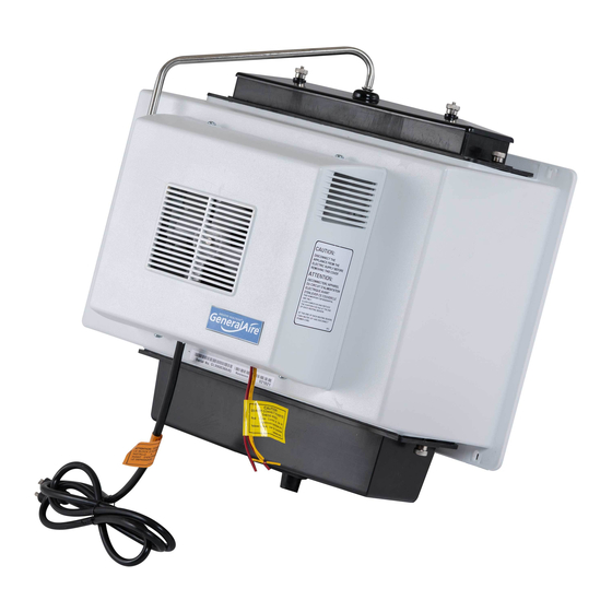
GeneralAire 1137 Series Installation Instructions Manual
Flow through power humidifier
Hide thumbs
Also See for 1137 Series:
- Installation & owner's manual (12 pages) ,
- Installation instructions manual (9 pages) ,
- Owner's manual (9 pages)
Table of Contents
Advertisement
Available languages
Available languages
Quick Links
RESIDENTIAL
AIR TREATMENT
PRODUCTS
INSTALLER:
PLEASE FILL OUT AND MAIL
GUARANTEE
CARD AFTER INSTALLATION
IS COMPLETE.
LEAVE INSTALLATION
INSTRUCTIONS
WITH HOMEOWNER
PRECAUTION:
The installer should be an experienced
service technician.
Disconnect
electrical power before
beginning installation.
Do not install where temperatures
fall below 32 degrees F or where plenum temperatures
exceed 200 degrees F. For maximum evaporative capacity, install this humidifier on the warm air supply plenum.
When wiring into a multi-speed blower circuit see Step 5C.
FLOW THROUGH
POWER
HUMIDIFIER
FOR INSTALLATION
ON A VERTICAL
SURFACE
OF THE WARM AIR PLENUM
OF ANY FORCED AIR FURNACE
ADDITIONAL
MATERIALS THAT MAY BE NECESSARY:
1.1/4" diameter plastic supply tubing or 1/4" copper supply tubing for hot water applications
2. air pressure switch (G.F. Model #12500 suggested)
3. junction box, 115 V. grounding outlet, cover and wire
Select location on vertical surface of warm air plenum for mounting
humidifier.
Stick mounting template in place making sure the template is
level. Do not install humidifier where the blanked off ends of a cooling coil
will restrict air flow to the humidifier.
Center punch all 6 mounting holes on the template and drill with an
1/8" drill bit. Cut out center section. Install one cabinet retaining clip
in each of two top holes to assist holding cabinet while installing six
cabinet screws. Install drain pan, evaporator pad and distributor
trough using thumb nuts provided.
COPPER
TUBING
PLASTIC
TUBI NG
i
J
Mount the self tapping saddle valve on either a cold or a hot water pipe.
A side or top mount is best to avoid clogging from pipe sediment.
Connect 1/4" O.D. tubing to the saddle valve.
Copper tubing requires a
brass compression nut and brass sleeve.
Plastic tubing requires a brass
insert inside the tubing, a plastic sleeve on the outside with a brass
compression
nut.
NOTE: DO NOT USE PLASTIC TUBING ON HOT WATER OR IN
CONTACT WITH ANY HOT PLENUM SURFACE OR DUCT.
INSTALLATION
OF THIS SADDLE VALVE MUST MEET OR EXCEED
LOCAL CODES AND ORDINANCES.
SADDLE VALVE INSTALLATION
INSTRUCTIONS
Copper Pipe
1. Retract piercing pin into valve body by turning handle
counterclockwise.
2. Screw valve body into upper bracket and tighten.
3. Place rubber gasket over piercing pin.
4. Assemble saddle valve over copper pipe using enclosed screws,
nuts and lower bracket.
5. Tighten screws evenly and firmly. Brackets should be parallel.
6. Complete compression
connection to saddle valve outlet.
7. Turn handle clockwise to pierce tubing and close saddle valve.
8. Turn handle counterclockwise
to open saddle valve, leave open for
several seconds to flush dirt from pipe and tubing.
Steel, Brass or Hard Plastic Pipe
1. Shut off water supply and drain pipe.
2. Turn handle clockwise to expose piercing pin and close saddle
valve.
3. Place rubber gasket over piercing pin.
4. Drill 1/8" hole in pipe using a hand crank drill to avoid shock hazard.
5. Assemble saddle valve over steel, brass or hard plastic pipe using
enclosed screws, nuts and lower bracket.
6. Tighten screws evenly and firmly. Brackets should be parallel.
7. Complete compression
connection to saddle valve outlet.
8. Turn handle counterclockwise
to open saddle valve, leave open for
several seconds to flush dirt from pipe and tubing.
Threaded Pipe Fittings
1. Turn handle clockwise to expose piercing pin and close saddle
valve.
2. Seal valve body threads using pipe tape or sealant.
3. Install valve into 1/8" NPT fitting.
4. Complete compression
connection to saddle valve outlet.
5. Turn handle counterclockwise
to open saddle valve, leave open for
several seconds to flush dirt from pipe and tubing.
Advertisement
Table of Contents

Subscribe to Our Youtube Channel
Related Manuals for GeneralAire 1137 Series


Summary of Contents for GeneralAire 1137 Series
- Page 1 RESIDENTIAL AIR TREATMENT PRODUCTS FLOW THROUGH INSTALLER: PLEASE FILL OUT AND MAIL GUARANTEE CARD AFTER INSTALLATION POWER HUMIDIFIER IS COMPLETE. LEAVE INSTALLATION INSTRUCTIONS WITH HOMEOWNER FOR INSTALLATION ON A VERTICAL PRECAUTION: The installer should be an experienced service technician. Disconnect electrical power before SURFACE OF THE WARM AIR PLENUM...
-
Page 2: Wiring Diagram
INSTRUCTIONS FOR WIRING Please refer to the installation instructions included with the Humidistat. Assemble distributor tube so that it is directed into the center opening of the distributor trough cover. Connect 1/4" water supply tube to brass filter at inlet of solenoid. DO NOT USE PLASTIC TUBING IN CONTACT WITH ANY HOT PLENUM SURFACE OR DUCT. - Page 3 HUMIDIFICATEUR PUISSANT RESIDENTIAL AIR TREATMENT PRODUCTS A CIRCULATION DIRECTE MODELE1137 INSTALLATEUR : VEUILLEZ REMPLIR ET POSTER LA CARTE DE GARANTIE UNE FOIS L'INSTALLATION TERMINEE. LAISSER LES DIRECTIVES D'INSTALLATION AU PROPRIETAIRE DE LA MAISON, PRECAUTION : L'installateur dolt etre un technicien qualifie et experiment& Couper I'alimentation electrique POUR L'INSTALLATION...
- Page 4 INSTRUCTIONS POUR LE C.&.BLAGE Veuillez consulter la notice d'installation fournie avec I'humidistat. Monter le tuyau du distributeur de fa£on qu'il se dirige vers I'ouverture centrale du couvercle du bac de distributeur. Raccorder le tuyau d'alimentation d'eau de 1/4 po au filtre en laiton de I'entree du solenofde.
- Page 5 1137-24 DISTRIBUTOR TUBE 1099-9 THUMB NUT 1137-35 TROUGH COVER 1137-4 DISTRIBUTOR TROUGH 1137-2 FAN SHROUD -- 990-13 EVAPORATOR 1137-9 FAN BLADE -- 1137-20 FAN GUARD SOLENOID VALVE ASS'Y 1137-17 1137-7 WIRING BRACKET 40-7 TINNERMAN 1137-8 MOTOR 1137-50 COOLING 1137-26 RELAY ASS'Y 1137-39 FRONT COVER ASS'Y -- P-103 COMPRESSION...
- Page 6 Magnuson-Moss Warranty Act.) GENERAL FILTERS, INC. 43800 GRAND RIVER AVE. NOVI, MICHIGAN 48375-1115 WWW.GENERALAIRE.COM CANADIAN GENERAL FILTERS, LTD. 39 CROCKFORD BLVD. SCARBOROUGH, ONTARIO M1R3B7 Your Humidifier is engineered to give helpful and trouble-free humidification. For maximum efficiency the following cleaning procedures...
- Page 7 1137-24 TUYAU DU DISTRIBUTEUR 1099-9 ECROU AAILETTES 1137-35 COUVERCLE DU BAC 1137-4 GOULOTTE DU DISTRIBUTEUR 1137-2 TUYERE DU VENTILATEUR 990-13 BLOC EVAPORATEUR 1137-9 PALE DE VENTILATEUR 1137-20 GRILLE DE PROTECTION DU VENTILATEUR 1137-17 VANNE ELECTROMAGNETIQUE 1137-7 SUPPORT DE CABLAGE 40-7 ECROU TINNERMAN 1137-8 MOTEUR DU VENTILATEUR 1137-50 VENTILATEUR...
- Page 8 BLVD. SCARBOROUGH, ONTARIO MIR3B7 WWW.CGFPRODUCTS.COM GENERAL FILTERS, INC. 43800 GRAND RIVER AVE. NOVI, MICHIGAN 48375-1115 WWW.GENERALAIRE.COM Votre humidificateur est congu pour fournir une humidification d'appoint sans problemes. Pour beneficier d'un fonctionnement maximum, suivre les @tapes de nettoyage ci-dessous & la fin de chaque saison froide ! 1.
- Page 9 1137-24 DISTRIBUTOR TUBE 1099-9 THUMB NUT 1137-35 TROUGH COVER 1137-4 DISTRIBUTOR TROUGH 1137-2 FAN SHROUD I 990-13 EVAPORATOR 1137-9 FAN BLADE -- 1137-20 FAN GUARD SOLENOID VALVE ASS'Y 1137-17 1137-7 WIRING BRACKET 40-7 TINNERMAN 1137-8 MOTOR 1137-50 COOLING 1137-26 RELAY ASS'Y 1137-39 FRONT COVER _1137-31 POWER SUPPLY...
Need help?
Do you have a question about the 1137 Series and is the answer not in the manual?
Questions and answers