Table of Contents
Advertisement
Advertisement
Table of Contents

Related Manuals for Supero X9DRD-7LN4F-JBOD


Summary of Contents for Supero X9DRD-7LN4F-JBOD
- Page 1 X9DRD-7LN4F-JBOD X9DRD-7LN4F USER’S MANUAL Revision 1.1a...
- Page 2 The information in this User’s Manual has been carefully reviewed and is believed to be accurate. The vendor assumes no responsibility for any inaccuracies that may be contained in this document, and makes no commitment to update or to keep current the information in this manual, or to notify any person or organization of the updates.
-
Page 3: About This Motherboard
E5-2600 (Socket R) Series Processors that offer QPI (Intel QuickPath Interface) Technology (V.1.1), providing point-to-point connection with a transfer speed of up to 8.0 TG/s. With the C602J built in, the X9DRD-7LN4F-JBOD/-7LN4F motherboard supports Intel® Manageability Engine (ME), Rapid Storage Technology, Digital Media Interface (DMI), PCI-E Gen. -
Page 4: Conventions Used In The Manual
X9DRD-7LN4F-JBOD/X9DRD-7LN4F Motherboard User’s Manual Conventions Used in the Manual Pay special attention to the following symbols for proper system installation and to prevent damage to the system or injury to yourself: Warning: Important information given to ensure proper system installation or to prevent damage to the components or injury to yourself;... -
Page 5: Contacting Supermicro
Preface Contacting Supermicro Headquarters Address: Super Micro Computer, Inc. 980 Rock Ave. San Jose, CA 95131 U.S.A. Tel: +1 (408) 503-8000 Fax: +1 (408) 503-8008 Email: marketing@supermicro.com (General Information) support@supermicro.com (Technical Support) Web Site: www.supermicro.com Europe Address: Super Micro Computer B.V. Het Sterrenbeeld 28, 5215 ML 's-Hertogenbosch, The Netherlands Tel:... -
Page 6: Table Of Contents
X9DRD-7LN4F-JBOD/X9DRD-7LN4F Motherboard User’s Manual Table of Contents Preface Chapter 1 Overview Overview ......................1-1 Processor and Chipset Overview..............1-11 Special Features ................... 1-12 PC Health Monitoring ..................1-12 ACPI Features ....................1-13 Power Supply ....................1-13 Super I/O ....................... 1-14 Advanced Power Management ..............1-14 ®... - Page 7 Table of Contents Front Control Panel Pin Defi nitions............... 2-23 NMI Button ....................2-23 Power LED ....................2-23 HDD LED ....................2-24 NIC1/NIC2 LED Indicators ............... 2-24 Overheat (OH)/Fan Fail/PWR Fail/UID LED ..........2-25 Power Fail LED ..................2-25 Reset Button ................... 2-26 Power Button ...................
- Page 8 X9DRD-7LN4F-JBOD/X9DRD-7LN4F Motherboard User’s Manual 2-10 SATA/SAS Connections ................2-42 Serial ATA Ports..................2-42 SAS2 Ports ....................2-42 Chapter 3 Troubleshooting Troubleshooting Procedures ................3-1 Technical Support Procedures ................ 3-5 Battery Removal and Installation ..............3-6 Frequently Asked Questions ................3-7 Returning Merchandise for Service..............
-
Page 9: Chapter 1 Overview
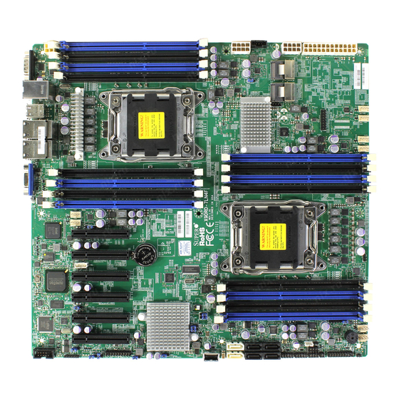
Chapter 1: Overview Chapter 1 Overview Overview Checklist Congratulations on purchasing your computer motherboard from an acknowledged leader in the industry. Supermicro boards are designed with the utmost attention to detail to provide you with the highest standards in quality and performance. Please check that the following items have all been included with your motherboard. - Page 10 X9DRD-7LN4F-JBOD/X9DRD-7LN4F Motherboard User’s Manual Motherboard Image Note: All graphics shown in this manual were based upon the latest PCB Revision available at the time of publishing of the manual. The motherboard you've received may or may not look exactly the same as the graphics...
- Page 11 Chapter 1: Overview Motherboard Layout VGA1 LAN2/4 USB2/3 LAN1/3 USB0/1 JUIDB COM2 LED3 COM1 LEDM1 JPW4 CTRL KB/Mouse IPMI_LAN FAN8 FAN7 CPU2 JBAT1 JBT1 Battery CMOS CLEAR Intel JUSB6 BIOS X9DRD-7LN4F Rev. 1.02 CPU1 JPW3 LSI SAS CTRL L-SAS0~3 L-SAS4~7 JPW2 BUZZER LED2...
- Page 12 Use only the correct type of onboard CMOS battery as specifi ed by the manufac- turer. Do not install the onboard battery upside down to avoid possible explosion. • X9DRD-7LN4F supports SAS Firmware IR mode; X9DRD-7LN4F-JBOD sup- ports SAS Firmware IT Mode. •...
- Page 13 SATA DOM (Device on Module) Power Connector JSTBY1 +5V Standby Power Header JTPM1 TPM (Trusted Platform Module)/Port 80 JUID UID (Unit Identifi cation) Switch LAN1/3, LAN2/4 Gigabit Ethernet Ports 1/2, 3/4 Note: X9DRD-7LN4F supports SAS Firmware IR mode, and X9DRD-7LN4F-JBOD uses SAS Firmware IT Mode.
- Page 14 X9DRD-7LN4F-JBOD/X9DRD-7LN4F Motherboard User’s Manual (IPMI) LAN IPMI_Dedicated LAN (I)SATA1~6 Intel SATA Connectors 1~6 from the Intel PCH (L)SAS0~3, 4~7 Serial_Link SCSI Attached 2.0 Connectors 0~3, 4~7 from the LSI SAS 2308 Controller Onboard Buzzer (Internal Speaker) ( C P U 1 ) S l o t s 1 / 2 / 6 , PCI-Express 3.0 x8 Slots (See Note Below)
-
Page 15: Motherboard Features
Chapter 1: Overview Motherboard Features • ® Dual Intel E5-2600 Series (Socket R-LGA 2011) pro- cessors; each processor supports two full-width Intel QuickPath Interconnect (QPI) links (with support of up to 25.6 GT/s per QPI link and with Data Transfer Rate of up to 8.0 GT/s per direction) •... - Page 16 X9DRD-7LN4F-JBOD/X9DRD-7LN4F Motherboard User’s Manual • RAID SATA RAID 0, 1, 5, 10 (Windows, Linux), SAS RAID 0, 1, 10 (X9DRD-7LN4F Only) Integrated IPMI 2.0 • IPMI 2.0 supported by the WPCM450 BMC Serial (COM) Port • Two (2) Fast UART 16550 Connection: 9-pin RS-232...
- Page 17 Chapter 1: Overview • Low noise fan speed control • System PECI (Platform Environment Confi guration Interface) Manage- 2.0 support ment • UID (Unit Identifi cation)/Remote UID • System resource alert via SuperDoctor® III • SuperoDoctor® III, Watch Dog, NMI •...
- Page 18 X9DRD-7LN4F-JBOD/X9DRD-7LN4F Motherboard User’s Manual X9DRD-7LN4F-JBOD/-7LN4F Block Diagram (AB) (AB) (CD) CPU REAR Socket 01 PROCESSOR SANDYBRIDGE CPU FRONT Socket 00 PROCESSOR SANDYBRIDGE (AB) (AB) (CD) (AB) (CD) BIOS J21 SLOT#1 SPI FLASH PCIE 3.0 x8 J22 SLOT#2 SATA Gen3 PCIE 3.0 x8...
-
Page 19: Processor And Chipset Overview
Chapter 1: Overview Processor and Chipset Overview Built upon the functionality and the capability of Intel E5-2600 Series (Socket R) processors and the C602J chipset, the X9DRD-7LN4F-JBOD/-7LN4F motherboard provides the performance and feature sets required for dual processor-based HPC/ Cluster/Database servers. -
Page 20: Special Features
X9DRD-7LN4F-JBOD/X9DRD-7LN4F Motherboard User’s Manual Special Features Recovery from AC Power Loss The Basic I/O System (BIOS) provides a setting that determines how the system will respond when AC power is lost and then restored to the system. You can choose for the system to remain powered off (in which case you must press the power switch to turn it back on), or for it to automatically return to the power-on state. -
Page 21: Acpi Features
It is even more important for processors that have high CPU clock rates. The X9DRD-7LN4F-JBOD/-7LN4F motherboard accommodates 24-pin ATX power supplies. Although most power supplies generally meet the specifi cations required by the CPU, some are inadequate. In addition, two 12V 8-pin, and the 4-pin power connections are also required to ensure adequate power supply to the system. -
Page 22: Super I/O
X9DRD-7LN4F-JBOD/X9DRD-7LN4F Motherboard User’s Manual It is strongly recommended that you use a high quality power supply that meets ATX power supply Specifi cation 2.02 or above. It must also be SSI compliant. (For more information, please refer to the website at http://www.ssiforum.org/). Additionally, in areas where noisy power transmission is present, you may choose to install a line fi... -
Page 23: Management Engine (Me)
Chapter 1: Overview Management Engine (ME) The Management Engine, which is an ARC controller embedded in the PCH, pro- vides Server Platform Services (SPS) to your system. The services provided by SPS are different from those provided by the ME on client platforms. Overview of the Nuvoton WPCM450 Controller The Nuvoton WPCM450 Controller, a Baseboard Management Controller (BMC), supports 2D/VGA-compatible Graphic Cores with PCI interface, creating multi-media... - Page 24 X9DRD-7LN4F-JBOD/X9DRD-7LN4F Motherboard User’s Manual • Provides remote Hardware Health Monitoring via IPMI. Key features • Provides Network Management Security via remote access/console redirection. • Supports the following Management tools: IPMIView, CLI (Command Line Interface) • RMCP+ protocol supported Note 1: For more information on IPMI confi guration, please refer to the IPMI User's Guide posted on our website at http://www.supermicro.com/...
-
Page 25: Chapter 2 Installation
Chapter 2: Installation Chapter 2 Installation Standardized Warning Statements The following statements are industry-standard warnings, provided to warn the user of situations which have the potential for bodily injury. Should you have questions or experience diffi culty, contact Supermicro's Technical Support department for assis- tance. - Page 26 X9DRD-7JLN4F/X9DRD-7LN4F Motherboard User’s Manual Attention Danger d'explosion si la pile n'est pas remplacée correctement. Ne la remplacer que par une pile de type semblable ou équivalent, recommandée par le fabricant. Jeter les piles usagées conformément aux instructions du fabricant. ¡Advertencia! Existe peligro de explosión si la batería se reemplaza de manera incorrecta.
-
Page 27: Product Disposal
Chapter 2: Installation Product Disposal Warning! Ultimate disposal of this product should be handled according to all national laws and regulations. 警告 本产品的废弃处理应根据所有国家的法律和规章进行。 警告 本產品的廢棄處理應根據所有國家的法律和規章進行。 Warnung Die Entsorgung dieses Produkts sollte gemäß allen Bestimmungen und Gesetzen des Landes erfolgen. ¡Advertencia! Al deshacerse por completo de este producto debe seguir todas las leyes y regla- mentos nacionales. -
Page 28: Static-Sensitive Devices
X9DRD-7JLN4F/X9DRD-7LN4F Motherboard User’s Manual ﺍﻟﻘﻮﺍﻧﻴﻦ ﻭﺍﻟﻠﻮﺍﺋﺢ ﺍﻟﻮﻁﻨﻴﺔ ﺠﻤﻴﻊ ﻭﻓﻘﺎ ﻟ ﻳﻨﺒﻐﻲ ﺍﻟﺘﻌﺎﻣﻞ ﻣﻌﻪ ﻫﺬﺍ ﺍﻟﻤﻨﺘﺞ ﻣﻦ ﺍﻟﺘﺨﻠﺺ ﺍﻟﻨﻬﺎﺋﻲ ﻋﻨﺪ Waarschuwing De uiteindelijke verwijdering van dit product dient te geschieden in overeenstemming met alle nationale wetten en reglementen. Static-Sensitive Devices Electrostatic Discharge (ESD) can damage electronic com ponents. To avoid dam- aging your system board, it is important to handle it very carefully. -
Page 29: Processor And Heatsink Installation
Chapter 2: Installation Processor and Heatsink Installation Warning: When handling the processor package, avoid placing direct pressure on the label area. Notes: • Always connect the power cord last, and always remove it before adding, removing or changing any hardware components. Make sure that you install the processor into the CPU socket before you install the CPU heatsink. - Page 30 X9DRD-7JLN4F/X9DRD-7LN4F Motherboard User’s Manual 2. Press the second load lever labeled 'Close 1st' to release the load plate that covers the CPU socket from its locking position. Pull lever away from Press down on Load the socket Lever 'Close 1st' 3.
- Page 31 Chapter 2: Installation 1. Use your thumb, and index fi ngers to loosen the lever and open the load plate. 2. Using your thumb and index fi nger, hold the CPU on its edges. Align the CPU keys, which are semi-circle cutouts, against the socket keys. Socket Keys CPU Keys 3.
- Page 32 X9DRD-7JLN4F/X9DRD-7LN4F Motherboard User’s Manual 4. With the CPU inside the socket, inspect the four corners of the CPU to make sure that the CPU is properly installed. 5. Close the load plate with the CPU inside the socket. Lock the lever labelled 'Close 1st' fi...
-
Page 33: Installing A Passive Cpu Heatsink
Chapter 2: Installation Installing a Passive CPU Heatsink 1. Do not apply any thermal grease to the heatsink or the CPU die -- the re- quired amount has already been applied. 2. Place the heatsink on top of the CPU so that the four mounting holes are aligned with those on the Motherboard's and the Heatsink Bracket under- neath. -
Page 34: Removing The Heatsink
X9DRD-7JLN4F/X9DRD-7LN4F Motherboard User’s Manual Removing the Heatsink Warning: We do not recommend that the CPU or the heatsink be removed. However, if you do need to uninstall the heatsink, please follow the instructions below to uninstall the heatsink to prevent damage done to the CPU or the CPU socket. 1. -
Page 35: Installing And Removing The Memory Modules
Chapter 2: Installation Installing and Removing the Memory Modules Note: Check Supermicro's website for recommended memory modules. CAUTION Exercise extreme care when installing or removing DIMM modules to prevent any possible damage. Installing & Removing DIMMs 1. Insert the desired number of DIMMs into the memory slots, starting with DIMM# A1. - Page 36 X9DRD-7JLN4F/X9DRD-7LN4F Motherboard User’s Manual Memory Support for the X9DRD-7LN4F-JBOD/7LN4F/ Motherboard The X9DRD-7LN4F-JBOD/-7LN4F motherboard supports 240-pin Registered (RDIMM)/Load Reduced (LRDIMM) ECC or Unbuffered (UDIMM) ECC/Non-ECC DDR3 800/1066/1333/1600 MHz memory modules of up to 512 GB in 16 DIMM modules. Please refer to our website a at http://www.supermicro.com/products/ motherboard.
- Page 37 Chapter 2: Installation Populating UDIMM (ECC/Non-ECC) Memory Modules Intel E5-2600 Series Processor UDIMM Memory Support Ranks Per Memory Capacity Speed (MT/s) and Voltage Validated by Slot per Channel DIMM & Per DIMM (SPC) and DIMM Per Channel (DPC) Data Width 1 Slot Per Channel 2 Slots Per Channel (See the Note below)
- Page 38 X9DRD-7JLN4F/X9DRD-7LN4F Motherboard User’s Manual Populating LRDIMM (ECC) Memory Modules Intel E5-2600 Series Processor LRDIMM Memory Support Ranks Per Memory Capacity Speed (MT/s) and Voltage Validated DIMM & Data Per DIMM by Slot per Channel (SPC) and Width DIMM Per Channel (DPC) 1 Slot Per 2 Slots Per (See the Note...
-
Page 39: Motherboard Installation
Chapter 2: Installation Motherboard Installation All motherboards have standard mounting holes to fi t different types of chassis. Make sure that the locations of all the mounting holes for both motherboard and chassis match. Although a chassis may have both plastic and metal mounting fas- teners, metal ones are highly recommended because they ground the motherboard to the chassis. -
Page 40: Installing The Motherboard
X9DRD-7JLN4F/X9DRD-7LN4F Motherboard User’s Manual Installing the Motherboard 1. Install the I/O shield into the chassis. 2. Locate the mounting holes on the motherboard. 3. Locate the matching mounting holes on the chassis. Align the mounting holes on the motherboard against the mounting holes on the chassis. 4. -
Page 41: Control Panel Connectors And I/O Ports
Chapter 2: Installation Control Panel Connectors and I/O Ports The I/O ports are color coded in conformance with the PC 99 specifi cation. See the picture below for the colors and locations of the various I/O ports. Back Panel Connectors and I/O Ports VGA1 LAN2/4 LAN1/3... -
Page 42: Serial Ports
X9DRD-7JLN4F/X9DRD-7LN4F Motherboard User’s Manual Serial Ports Serial COM) Ports Pin Defi nitions Two COM connections (COM1 & Pin # Defi nition Pin # Defi nition COM2) are located on the mother- board. COM1 is located on the Back- plane I/O panel. COM2, located close to CPU1 Slot1, provides front access support. -
Page 43: Universal Serial Bus (Usb)
Chapter 2: Installation Universal Serial Bus (USB) FP USB (4/5, 8/9, USB 6) Backplane Pin Defi nitions USB (0/1, 2/3) Four Universal Serial Bus ports (USB Pin Defi nitions USB 4, 8, 6, USB 5, 9 0/1, USB 2/3) are located on the I/O Pin # Defi... -
Page 44: Ethernet Ports
X9DRD-7JLN4F/X9DRD-7LN4F Motherboard User’s Manual Ethernet Ports LAN Ports Pin Defi nition Four Gigabit Ethernet ports (LAN1/2, Pin# Defi nition LAN3/4) are located on the I/O back- P2V5SB SGND plane on the motherboard. In addition, TD0+ Act LED an IPMI_Dedicated LAN is located TD0- P3V3SB above USB 0/1 ports on the backplane... -
Page 45: Unit Identifi Er Switch/Uid Led Indicators
Chapter 2: Installation Unit Identifi er Switch/UID LED Indicators UID Switch A Unit Identifi er (UID) Switch and two LED Indi- Pin# Defi nition cators are located on the motherboard. The UID Ground Switch is located next to the VGA port on the Ground backplane. -
Page 46: Front Control Panel
X9DRD-7JLN4F/X9DRD-7LN4F Motherboard User’s Manual Front Control Panel JF1 contains header pins for various buttons and indicators that are normally lo- cated on a control panel at the front of the chassis. These connectors are designed specifi cally for use with Supermicro's server chassis. See the fi gure below for the descriptions of the various control panel buttons and LED indicators. -
Page 47: Front Control Panel Pin Defi Nitions
Chapter 2: Installation Front Control Panel Pin Defi nitions NMI Button NMI Button Pin Defi nitions (JF1) The non-maskable interrupt button Pin# Defi nition header is located on pins 19 and 20 Control of JF1. Refer to the table on the right Ground for pin defi... -
Page 48: Hdd Led
X9DRD-7JLN4F/X9DRD-7LN4F Motherboard User’s Manual HDD LED HDD LED Pin Defi nitions (JF1) The HDD LED connection is located Pin# Defi nition on pins 13 and 14 of JF1. Attach a 3.3V Standby cable here to indicate HDD activ- HD Active ity. -
Page 49: Overheat (Oh)/Fan Fail/Pwr Fail/Uid Led
Chapter 2: Installation Overheat (OH)/Fan Fail/PWR Fail/ OH/Fan Fail/ PWR Fail/Blue_UID UID LED LED Pin Defi nitions (JF1) Pin# Defi nition Connect an LED cable to pins 7 and Red_LED-Cathode/OH/Fan Fail/ 8 of Front Control Panel to use the Power Fail5.5V.SB Overheat/Fan Fail/Power Fail and Blue_UID LED UID LED connections. -
Page 50: Reset Button
X9DRD-7JLN4F/X9DRD-7LN4F Motherboard User’s Manual Reset Button Reset Button Pin Defi nitions (JF1) The Reset Button connection is located Pin# Defi nition on pins 3 and 4 of JF1. Attach it to a Reset hardware reset switch on the computer Ground case. -
Page 51: Connecting Cables
Chapter 2: Installation Connecting Cables ATX Power 24-pin Connector Pin Defi nitions Power Connectors Pin# Defi nition Pin # Defi nition A 24-pin main power supply connector(JPW1), +3.3V +3.3V two 8-pin CPU power connectors (JPW2/3) and -12V +3.3V a 4-pin power connector (JPW4) are located on the motherboard. -
Page 52: Fan Headers
X9DRD-7JLN4F/X9DRD-7LN4F Motherboard User’s Manual Fan Headers Fan Header Pin Defi nitions This motherboard has eight system/CPU Pin# Defi nition fan headers (Fan 1~Fan 8) on the moth- Ground erboard. All these 4-pin fans headers are +12V backward compatible with the traditional Tachometer 3-pin fans. -
Page 53: Internal Speaker
Chapter 2: Installation Internal Speaker Internal Buzzer (SP1) Pin Defi nition The Internal Speaker, located at SP1, Pin# Defi nitions can be used to provide audible indica- Pin 1 Pos. (+) Beep In tions for various beep codes. See the Pin 2 Neg. -
Page 54: Tpm Header/Port 80
X9DRD-7JLN4F/X9DRD-7LN4F Motherboard User’s Manual TPM Header/Port 80 TPM/Port 80 Header Pin Defi nitions A Trusted Platform Module/Port 80 Pin # Defi nition Pin # Defi nition header is located at JTPM1 to provide LCLK TPM support and Port 80 connection. LFRAME# <(KEY)>... -
Page 55: Power Smb (I C) Connector
Chapter 2: Installation Power SMB (I C) Connector PWR SMB Pin Defi nitions Power System Management Bus (I Pin# Defi nition Connector (JPI C1) monitors power Clock supply, fan and system temperatures. Data See the table on the right for pin PWR Fail defi... -
Page 56: T-Sgpio 1/2 Headers
X9DRD-7JLN4F/X9DRD-7LN4F Motherboard User’s Manual T-SGPIO 1/2 Headers T-SGPIO 1/2 Pin Defi nitions Two SGPIO (Serial Link General Pin# Defi nition Defi nition Purpose Input/Output) headers are located on the motherboard. T-SGPIO Ground Data 1/2 provide onboard SATA support on Load Ground the motherboard. -
Page 57: Standby Power Header
Chapter 2: Installation Standby Power Header Standby PWR Pin Defi nitions The +5V Standby Power header is lo- Pin# Defi nition cated at JSTBY1 on the motherboard. +5V Standby See the table on the right for pin defi ni- Ground tions. -
Page 58: Jumper Settings
X9DRD-7JLN4F/X9DRD-7LN4F Motherboard User’s Manual Jumper Settings Explanation of Jumpers Connector Pins To modify the operation of the mother- board, jumpers can be used to choose between optional settings. Jumpers create Jumper shorts between two pins to change the function of the connector. Pin 1 is identifi ed with a square solder pad on the printed Setting circuit board. -
Page 59: Cmos Clear
Chapter 2: Installation CMOS Clear JBT1 is used to clear CMOS. Instead of pins, this "jumper" consists of contact pads to prevent accidental clearing of CMOS. To clear CMOS, use a metal object such as a small screwdriver to touch both pads at the same time to short the connection. Always remove the AC power cord from the system before clearing CMOS. -
Page 60: Vga Enable
X9DRD-7JLN4F/X9DRD-7LN4F Motherboard User’s Manual VGA Enable VGA Enable Jumper Settings Jumper JPG1 allows the user to enable Jumper Setting Defi nition the onboard VGA connector. The default Enabled (Default) setting is 1-2 to enable the connection. Disabled See the table on the right for jumper settings. -
Page 61: Management Engine (Me) Recovery
Chapter 2: Installation Management Engine (ME) Recovery ME Recovery Jumper Settings Use Jumper JPME1 to select ME Firm- Jumper Setting Defi nition ware Recovery mode, which will limit Normal (Default) resource allocation for essential system ME Recovery operation only in order to maintain nor- mal power operation and management. -
Page 62: I 2 C Bus To Pci-Exp. Slots
X9DRD-7JLN4F/X9DRD-7LN4F Motherboard User’s Manual C Bus to PCI-Exp. Slots C to PCI-E slots Jumper Settings Use Jumpers JI C1 and JI C2 to connect Jumper Setting Defi nition the System Management Bus (I C) to Closed Enabled (Default) PCI-Express slots in order to improve Open Disabled PCI slot performance. -
Page 63: Onboard Led Indicators
Chapter 2: Installation Onboard LED Indicators Link LED Activity LED GLAN LEDs The Gigabit LAN ports are located on the IO Backplane on the motherboard. Each Link LED Activity LED Ethernet LAN port has two LEDs. The Yel- Rear View (when facing the rear side of the chassis) low LED indicates activity. -
Page 64: Onboard Power Led
X9DRD-7JLN4F/X9DRD-7LN4F Motherboard User’s Manual Onboard Power LED Onboard PWR LED Indicator LED States An Onboard Power LED is located at LED Color Defi nition LED2 on the motherboard. When this System Off (PWR cable not connected) LED is on, the system is on. Be sure to Green System On turn off the system and unplug the power... -
Page 65: Unit Identifi Cation Switch/Led
Chapter 2: Installation Unit Identifi cation Switch/LED UID LED Status A Unit Identifi er switch (UID) and a Color/State OS Status rear UID LED indicator (LED3) are Blue: On Windows OS Unit Identifi ed located next to LAN ports on the back Blue: Linux OS Unit Identifi... -
Page 66: 2-10 Sata/Sas Connections
X9DRD-7JLN4F/X9DRD-7LN4F Motherboard User’s Manual 2-10 SATA/SAS Connections Serial ATA Ports SATA/SAS Pin Defi nitions There are six Serial ATA Ports (I-SATA1~I-SATA6) Pin# Defi nition located on the motherboard, including four SATA2 Ground ports and two SATA3 ports. These ports provide TX_P serial-link signal connections, which are faster than TX_N... -
Page 67: Chapter 3 Troubleshooting
Chapter 3: Troubleshooting Chapter 3 Troubleshooting Troubleshooting Procedures Use the following procedures to troubleshoot your system. If you have followed all of the procedures below and still need assistance, refer to the ‘Technical Support Procedures’ and/or ‘Returning Merchandise for Service’ section(s) in this chapter. Note: Always disconnect the power cord before adding, changing or installing any hardware components. -
Page 68: System Boot Failure
X9DRD-7LN4F-JBOD/X9DRD-7LN4F Motherboard User’s Manual No Video 1. If the power is on, but you have no video, remove all the add-on cards and cables. 2. Use the speaker to determine if any beep codes exist. Refer to Appendix A for details on beep codes. -
Page 69: Memory Errors
Chapter 3: Troubleshooting Memory Errors When a No-Memory Beep Code is issued by the system, check the following: 1. Make sure that the memory modules are compatible with the system and that the DIMM modules are properly and fully installed. (For memory compatibility, refer to the Memory Compatibility Chart posted on our website @ http://www. - Page 70 X9DRD-7LN4F-JBOD/X9DRD-7LN4F Motherboard User’s Manual tings in the BIOS to make sure that the CPU and System temperatures are within the normal range. Also check the front panel Overheat LED, and make sure that the Overheat LED is not on. 5. Adequate power supply: Make sure that the power supply provides adequate power to the system.
-
Page 71: Technical Support Procedures
Chapter 3: Troubleshooting Technical Support Procedures Before contacting Technical Support, please take the following steps. Also, please note that as a motherboard manufacturer, Supermicro also sells motherboards through its channels, so it is best to fi rst check with your distributor or reseller for troubleshooting services. -
Page 72: Battery Removal And Installation
X9DRD-7LN4F-JBOD/X9DRD-7LN4F Motherboard User’s Manual Battery Removal and Installation Battery Removal To remove the onboard battery, follow the steps below: 1. Power off your system and unplug your power cable. 2. Locate the onboard battery as shown below. 3. Using a tool such as a pen or a small screwdriver, push the battery lock out- wards to unlock it. -
Page 73: Frequently Asked Questions
Chapter 3: Troubleshooting Frequently Asked Questions Question: What are the various types of memory that my motherboard can support? Answer: The motherboard supports Registered (RDIMM)/Load Reduced (LRDIMM) ECC or Unbuffered (UDIMM) ECC/Non-ECC DDR3 modules. To enhance memory performance, do not mix memory modules of different speeds and sizes. Please follow all memory installation instructions given on Section 2-4 in Chapter 2. -
Page 74: Returning Merchandise For Service
X9DRD-7LN4F-JBOD/X9DRD-7LN4F Motherboard User’s Manual Returning Merchandise for Service A receipt or copy of your invoice marked with the date of purchase is required before any warranty service will be rendered. You can obtain service by calling your ven- dor for a Returned Merchandise Authorization (RMA) number. When returning the... -
Page 75: Chapter 4 Bios
BIOS Introduction This chapter describes the AMI BIOS Setup utility for the X9DRD-7LN4F-JBOD/ X9DRD-7LN4F It also provides the instructions on how to navigate the AMI BIOS Setup utility screens. The AMI ROM BIOS is stored in a Flash EEPROM and can be easily updated. -
Page 76: Main Setup
X9DRD-7LN4F-JBOD/X9DRD-7LN4F Motherboard User’s Manual How To Change the Confi guration Data The confi guration data that determines the system parameters may be changed by entering the AMI BIOS Setup utility. This Setup utility can be accessed by pressing <Delete> at the appropriate time during system boot. - Page 77 Chapter 4: AMI BIOS System Date/System Time Use this option to change the system time and date. Highlight System Time or System Date using the arrow keys. Enter new values through the keyboard and press <Enter>. Press the <Tab> key to move between fi elds. The date must be entered in Day MM/DD/YY format.
-
Page 78: Advanced Setup Confi Gurations
X9DRD-7LN4F-JBOD/X9DRD-7LN4F Motherboard User’s Manual Advanced Setup Confi gurations Select the Advanced tab to access the following submenu items. Boot Feature Quiet Boot This feature allows the user to select bootup screen display between POST mes- sages and the OEM logo. Select Disabled to display the POST messages. Select Enabled to display the OEM logo instead of the normal POST messages. - Page 79 Chapter 4: AMI BIOS at bootup and allow the drives that are attached to these host adaptors to function as bootable disks. If this item is set to Disabled, the ROM BIOS of the host adap- tors will not capture Interrupt 19, and the drives attached to these adaptors will not function as bootable devices.
- Page 80 X9DRD-7LN4F-JBOD/X9DRD-7LN4F Motherboard User’s Manual • Processor Cores • Intel HT (Hyper-Threading) Technology • Intel VT-x Technology • Intel SMX Technology • L1 Data Cache / L1 Code Cache • L2 Cache • L3 Cache CPU Speed This item displays the speed of the CPU installed in Socket 1/Socket 2.
- Page 81 Chapter 4: AMI BIOS Execute-Disable Bit (Available if supported by the OS & the CPU) Select Enabled to enable the Execute Disable Bit which will allow the processor to designate areas in the system memory where an application code can execute and where it cannot, thus preventing a worm or a virus from fl...
- Page 82 X9DRD-7LN4F-JBOD/X9DRD-7LN4F Motherboard User’s Manual CPU Power Management Confi guration This submenu allows the user to confi gure the following CPU Power Manage- ment settings. Power Technology Select Energy Effi ciency to support power-saving mode. Select Custom to cus- tomize system power settings. Select Disabled to disable power-saving settings.
- Page 83 Chapter 4: AMI BIOS Package C-State limit (Available when Power Technology is set to Custom) This feature allows the user to set the limit on the C-State package register. The options are C0, C2, C6, and No Limit. Energy/Performance Bias Use this feature to select an appropriate fan setting to achieve maximum system performance (with maximum cooling) or maximum energy effi...
-
Page 84: North Bridge
X9DRD-7LN4F-JBOD/X9DRD-7LN4F Motherboard User’s Manual Chipset Confi guration North Bridge This feature allows the user to confi gure the settings for the Intel North Bridge. Integrated IO Confi guration Intel ® VT-d Select Enabled to enable Intel Virtualization Technology support for Direct I/O VT-d by reporting the I/O device assignments to the VMM (Virtual Machine Monitor) through the DMAR ACPI Tables. - Page 85 Chapter 4: AMI BIOS IIO 2 PCIe Port Bifurcation Control This submenu confi gures the following IO PCIe Port Bifurcation Control settings for IIO 2 PCIe ports to determine how the available PCI-Express lanes to be distributed between the PCI-Exp. Root ports. QPI Confi...
- Page 86 X9DRD-7LN4F-JBOD/X9DRD-7LN4F Motherboard User’s Manual DIMM Information CPU Socket 1 DIMM Information, CPU Socket 2 DIMM Information The status of the memory modules detected by the BIOS will be displayed as detected by the BIOS. Memory Mode When Independent is selected, all DIMMs are available to the operating system.
- Page 87 Chapter 4: AMI BIOS correctable error, the error is corrected and sent to the requestor (the original source). Memory is updated as well. Select Enabled to use Demand Scrubbing for ECC memory correction. The options are Enabled and Disabled. Data Scrambling Select Enabled to enable data scrambling to ensure data security and integrity.
- Page 88 X9DRD-7LN4F-JBOD/X9DRD-7LN4F Motherboard User’s Manual Port 60/64 Emulation Select Enabled to enable I/O port 60h/64h emulation support for the legacy USB keyboard so that it can be fully supported by the operating systems that does not recognize a USB device. The options are Disabled and Enabled.
- Page 89 Chapter 4: AMI BIOS Port 0~5 Hot Plug Select Enabled to enable hot-plug support for a particular port, which will allow the user to change a hardware component or device without shutting down the system. The options are Enabled and Disabled. Staggered Spin Up Select Enabled to enable Staggered Spin-up support to prevent excessive power consumption caused by multiple HDDs spinning-up simultaneously.
- Page 90 X9DRD-7LN4F-JBOD/X9DRD-7LN4F Motherboard User’s Manual SERR# Generation Select Enabled to allow a PCI device to generate an SERR number for a PCI Bus Signal Error Event. The options are Enabled and Disabled. Maximum Payload Select Auto to allow the system BIOS to automatically set the maximum payload value for a PCI-E device to enhance system performance.
- Page 91 Chapter 4: AMI BIOS VGA Priority This feature allows the user to select the graphics adapter to be used as the primary boot device. The options are Onboard, and Offboard. Network Stack Select Enabled enable PXE (Preboot Execution Environment) or UEFI (Unifi ed Extensible Firmware Interface) for network stack support.
-
Page 92: Serial Port Console Redirection
X9DRD-7LN4F-JBOD/X9DRD-7LN4F Motherboard User’s Manual Change Settings This option specifi es the base I/O port address and the Interrupt Request address of Serial Port 2. Select Disabled to prevent the serial port from accessing any system resources. When this option is set to Disabled, the serial port becomes unavailable. - Page 93 Chapter 4: AMI BIOS client computer. A lower transmission speed may be required for long and busy lines. The options are 9600, 19200, 38400, 57600 and 115200 (bits per second). Data Bits Use this feature to set the data transmission size for Console Redirection. The options are 7 Bits and 8 Bits.
- Page 94 X9DRD-7LN4F-JBOD/X9DRD-7LN4F Motherboard User’s Manual Putty KeyPad This feature selects Function Keys and KeyPad settings for Putty, which is a terminal emulator designed for the Windows OS. The options are VT100, LINUX, XTERMR6, SC0, ESCN, and VT400. Serial Port for Out-of-Band Management/Windows Emergency Management Services (EMS) The submenu allows the user to confi...
-
Page 95: Acpi Settings
Chapter 4: AMI BIOS Data Bits, Parity, Stop Bits The status of these features is displayed. ACPI Settings Use this feature to confi gure Advanced Confi guration and Power Interface (ACPI) power management settings for your system. ACPI Sleep State Use this feature to select the ACPI State when the system is in sleep mode. - Page 96 X9DRD-7LN4F-JBOD/X9DRD-7LN4F Motherboard User’s Manual Pending Operation Use this item to schedule an operation for the security device. The options are None, Enable Take Ownership, Disable Take Ownership, and TPM Clear. Note: During restart, the computer will reboot in order to execute the pend- ing operation and change the state of the security device.
- Page 97 Chapter 4: AMI BIOS TPM Support: Trusted Platform support TPM State: Trusted Platform state ME Subsystem This feature displays the following ME Subsystem Confi guration settings. • ME BIOS Interface Version • ME Version iSCSI Confi guration: This item displays iSCSI confi guration information: iSCSI Initiator Name This item displays the name of the iSCSI Initiator, which is a unique name used in the world.
- Page 98 X9DRD-7LN4F-JBOD/X9DRD-7LN4F Motherboard User’s Manual Blink LEDs This feature allows the user to specify the duration for LEDs to blink. The range is from 0 ~ 15 seconds. The default setting is 0. PORT CONFIGURATION INFORMATION This section displays the following port information: •...
-
Page 99: Event Logs
Chapter 4: AMI BIOS Event Logs Select the Event Logs tab to access the following submenu items. Change SMBIOS Event Log Settings This feature allows the user to confi gure SMBIOS Event settings. Enabling/Disabling Options SMBIOS Event Log Select Enabled to enable SMBIOS (System Management BIOS) Event Logging during system boot. - Page 100 X9DRD-7LN4F-JBOD/X9DRD-7LN4F Motherboard User’s Manual Erasing Settings Erase Event Log Select Enabled to erase the SMBIOS (System Management BIOS) Event Log, which is completed before a event logging is initialized upon system reboot. The options are No, Yes, Next reset, and Yes, Every reset.
-
Page 101: Ipmi
Chapter 4: AMI BIOS IPMI Select the IPMI (Intelligent Platform Management Interface) tab to access the fol- lowing submenu items. IPMI Firmware Revision This item indicates the IPMI fi rmware revision used in your system. IPMI Status This item indicates the status of the IPMI fi rmware installed in your system. ... - Page 102 X9DRD-7LN4F-JBOD/X9DRD-7LN4F Motherboard User’s Manual When SEL is Full This feature allows the user to decide what the BIOS should do when the system event log is full. Select Erase Immediately to erase all events in the log when the system event log is full. The options are Do Nothing and Erase Immediately.
-
Page 103: Boot
Chapter 4: AMI BIOS Gateway IP Address This item displays the Gateway IP address for this computer. This should be in decimal and in dotted quad form (i.e., 192.168.10.253). Boot This submenu allows the user to confi gure the following boot settings for the system. -
Page 104: Security
X9DRD-7LN4F-JBOD/X9DRD-7LN4F Motherboard User’s Manual Security This menu allows the user to confi gure the following security settings for the system. Password Check Use this feature to determine when a password entry is required. Select Setup to require the password only when entering setup. Select Always to require the pass- word when entering setup and on each boot. -
Page 105: Save & Exit
Chapter 4: AMI BIOS Save & Exit This submenu allows the user to confi gure the Save and Exit settings for the system. Discard Changes and Exit Select this option to quit the BIOS Setup without making any permanent changes to the system confi... - Page 106 X9DRD-7LN4F-JBOD/X9DRD-7LN4F Motherboard User’s Manual Discard Changes Select this feature and press <Enter> to discard all the changes and return to the BIOS setup. When the dialog box appears, asking you if you want to load previ- ous values, select Yes to load the values previous saved, or select No to keep the changes you've made so far.
-
Page 107: Appendix A Bios Error Beep Codes
Appendix A: BIOS POST Error Codes Appendix A BIOS Error Beep Codes During the POST (Power-On Self-Test) routines, which are performed at each system boot, errors may occur. Non-fatal errors are those which, in most cases, allow the system to continue to boot. - Page 108 X9DRD-7LN4F-JBOD/X9DRD-7LN4F Motherboard User’s Manual Notes...
-
Page 109: Appendix B Software Installation Instructions
Appendix B: Software Installation Instructions Appendix B Software Installation Instructions B-1 Installing Software Programs The Supermicro ftp site contains drivers and utilities for your system at ftp://ftp. supermicro.com. Some of these must be installed, such as the chipset driver. After accessing the ftp site, go into the CDR_Images directory and locate the ISO fi... -
Page 110: B-2 Confi Guring Superdoctor® Iii
X9DRD-7LN4F-JBOD/X9DRD-7LN4F Motherboard User’s Manual Note 2: When making a storage driver diskette by booting into a Driver CD, please set the SATA Confi guration to "Compatible Mode" and confi gure SATA as IDE in the BIOS Setup. After making the driver diskette, be sure to change the SATA settings back to your original settings. - Page 111 SuperDoctor® III Interface Display Screen-II (Remote Control) Note: SD III Software Revision 1.0 can be downloaded from our Web Site at: ftp://ftp.supermicro.com/utility/Supero_Doctor_III/. You can also download the SDIII User's Guide at: <http://www.supermicro.com/PROD- UCT/Manuals/SDIII/UserGuide.pdf>. For Linux, we will recommend using Supero Doctor II.
- Page 112 X9DRD-7LN4F-JBOD/X9DRD-7LN4F Motherboard User’s Manual Notes...
- Page 113 (Disclaimer Continued) The products sold by Supermicro are not intended for and will not be used in life support systems, medical equipment, nuclear facilities or systems, aircraft, aircraft devices, aircraft/emergency communication devices or other critical systems whose failure to perform be reasonably expected to result in signifi cant injury or loss of life or catastrophic property damage.
Need help?
Do you have a question about the X9DRD-7LN4F-JBOD and is the answer not in the manual?
Questions and answers