
Related Manuals for LDG Z-11ProII


Summary of Contents for LDG Z-11ProII
- Page 1 Z-11PROII OPERATIONS MANUAL MANUAL REV A LDG Z-11ProII 100-Watt Automatic Tuner LDG Electronics 1445 Parran Road St. Leonard MD 20685-2903 USA Phone: 410-586-2177 Fax: 410-586-8475 ldg@ldgelectronics.com www.ldgelectronics.com PAGE 1...
-
Page 2: Table Of Contents
Table Of Contents Introduction Jumpstart, or “Real hams don’t read manuals!” Specifications An Important Word About Power Levels Important Safety Warning Getting to know your Z-11ProII Front Panel Rear Panel Installation Optional Internal Battery Installation Operation Basic Operation Basic Tuning... -
Page 3: Introduction
Connect the 50 ohm coax antenna feedline to the “ANT” jack on the Z-11ProII. Connect the Z-11ProII to a source of 7 to 16 volts DC @ 250mA, using the 2.5x5.5mm power jack on the rear of the Z-11ProII (center positive). -
Page 4: Specifications
Weight: 1 pound 6 ounces (without internal batteries). AN IMPORTANT WORD ABOUT POWER LEVELS The Z-11ProII is rated at 125 watts maximum power input at most. Many ham transmitters and transceivers, and virtually all amplifiers, output well over 125 watts. Power levels that significantly exceed specifications will definitely damage or destroy your Z-11ProII. -
Page 5: Getting To Know Your Z-11Proii
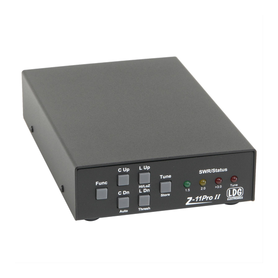
If no memorized settings are available, the tuner runs a full tuning cycle, storing the parameters for memory recall on subsequent tuning cycles on that frequency. In this manner, the Z-11ProII “learns” as it is used, adapting to the bands and frequencies as it goes. Front Panel On the front panel there are six pushbuttons and four LED indicator lights. -
Page 6: Rear Panel
Rear Panel The rear panel of the Z-11ProII features five connectors. ANT connector: Connect the 50-ohm coax antenna feedline to this standard SO-239 connector. GND connector (wing nut): Connect to antenna system ground. TX connector: Connect a 50-ohm coax jumper cable from this standard SO-239 connector to the ANT jack on the back of the transceiver. -
Page 7: Installation
. This cable has a 2.5x5.5mm coaxial plug on the end. Plug the coaxial plug into the 12 VDC Power jack on the rear of the Z-11ProII, and connect the other end to a DC power source between 11 and 16 volts DC, capable of supplying up to 300 mA. - Page 8 PAGE 8...
-
Page 9: Optional Internal Battery Installation
The Z-11ProII will operate on any input voltage from 7 to 16 volts DC, which opens up a wide range of internal battery possibilities. The most common would be 6 or 8 AA or AAA batteries in a battery holder, with the holder double-sided-taped to the top of the relay bank. -
Page 10: Operation
Battery life will vary depending upon usage and the type of battery selected, but in most cases, the batteries will last at least one year before requiring replacement. Remove batteries from the Z-11ProII when the unit will not be used for an extended period of time, to prevent possible damage due to battery leakage. -
Page 11: Basic Tuning
In this manner, the Z-11ProII “learns”; the longer you use it, the more closely it adapts itself to the bands and frequencies used. Most users will probably use memory tuning most of the time;... -
Page 12: Toggle Bypass Mode
The tuner may also be placed in “bypass” mode where it is electrically removed from the antenna system. Toggle Bypass Mode To toggle between bypassed and active mode, press the front panel TUNE button on the Z- 11ProII momentarily. All four LEDs will flash three times to indicate that the tuner is in bypass mode. -
Page 13: Toggle Automatic / Semiautomatic Tuning Mode
Toggle Automatic / Semiautomatic Tuning Mode As described above, the Z-11ProII employs a fully automatic and a semi-automatic tuning mode. To toggle between the two, press and release the FUNC button, and then press the C DN/AUTO button. When Automatic tuning mode is selected, the inner two LEDs will blink. -
Page 14: Manual Full Tuning
25 watts or less. In no case should you transmit more than 125 watts. If the memory tune is not successful, the Z-11ProII falls through to full tuning cycle. At the end of a tuning cycle, the LEDs cycle inwards to indicate a successful tune. -
Page 15: Tuning Status / Error Indication
SWR once tuning is complete. Tuning Status / Error Indication During normal operation, the front panel LEDs on the Z-11ProII are extinguished during receive, and will light up to indicate the current SWR reading upon transmit. SWR levels may be decoded as follows: During or after tuning, the LEDs can indicate error conditions as well. -
Page 16: Tuning Status Reports
Tuning Status Reports Condition Report Outer LEDs light, then inner LEDs. Successful tune All LEDs blink twice. RF Lost during tune All LEDs blink three times. No RF found Leftmost three LEDs blink twice. No match found PAGE 16... -
Page 17: Advanced Operation
In some rare cases, after tuning, it may be desirable to adjust the inductance and capacitance settings that the Z-11ProII came up with during the tuning process. This is more likely to occur when attempting to tune an antenna far from its resonant frequency. -
Page 18: Set Automatic Tuning Swr Threshold
Set Automatic Tuning SWR Threshold When the Z-11ProII is in fully automatic tuning mode, it begins tuning any time RF is present, and the SWR exceeds a preset threshold. That threshold may be programmed to any desired value between 1.5:1 and 3.0: To set the SWR threshold, press FUNC then L Dn / Thresh. -
Page 19: Command Summary
The only requirement is that the tuner remains dry. If it is desired that the Z-11ProII is positioned farther from the transceiver than the optional cable length allows, a custom cable will need to be constructed. This can be accomplished in two ways: Cut the optional cable and solder a jumper wire between all the connections, or purchase new connectors and cable to construct a custom-length interface cable from scratch. -
Page 20: Theory Of Operation
, but a little background will help in understanding what the Z-11ProII is doing, and how it does it. In simple DC circuits, the wire resists current flow, converting some of it into heat. The relationship between voltage, current, and resistance is described by the elegant and well-known “Ohm’s Law”, named for Georg Simon Ohm of Germany, who first discovered the principle in... -
Page 21: The Ldg Z-11Proii
Simple tuners use variable capacitors and inductors; the operator adjusts them by hand while observing reflected power on the SWR meter until a minimum SWR is reached. The LDG Electronics Z-11ProII automates this process. - Page 22 This allows the Z-11ProII to handle loads that are either greater than or less than 50 ohms. All relays are sized to carry 125 watts continuously.
-
Page 23: A Word About Tuning Etiquette
LDG products our website also has complete product specifications and photographs you can use to help make your purchase decision. Don’t forget the links to all of the quality LDG Dealers also ready to help you make that purchase decision. -
Page 24: Out Of Warranty Service
Ask your shipper for a tracking number or a delivery verification receipt. This way you know the product arrived safely at LDG. Be sure to give us your email address so our shipper can alert you online when your product is en-route back to you. Please be assured that our staff makes every effort to complete repairs ahead of our published wait time.
Need help?
Do you have a question about the Z-11ProII and is the answer not in the manual?
Questions and answers