Table of Contents
Advertisement
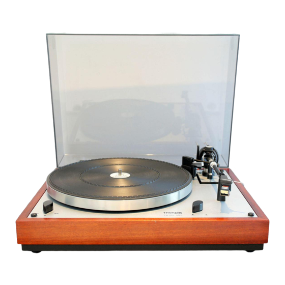
THORENS TD 146 and TD 166 MKII Owner's Manual
Contents
Introduction
I.
II.
Assembling
the turntable
III.
Electrical
and
installation
IV.
Tracking
force
adjustment
V.
Antiskating
adjustment
VI.
Operation of
the TD 146
VII.
Operation of
the TD 166
MkII
VIII.
Mounting
and
adjustment
of the
pickup
cartridge
IX.
Technical
specifications
X.
THORENS
factory
warranty
Please send any questions, comments, or corrections to:
Ron Stewart (rgs@hiwaay.net)
Advertisement
Table of Contents

Related Manuals for THORENS TD 146


Summary of Contents for THORENS TD 146
- Page 1 THORENS TD 146 and TD 166 MKII Owner's Manual Contents Introduction Unpacking Assembling the turntable III. Electrical connections installation Tracking force adjustment Antiskating adjustment Operation of the TD 146 VII. Operation of the TD 166 MkII VIII. Mounting adjustment of the...
- Page 2 Links Here are links to some other pages with information about Thorens turntables and other vintage equipment. The Analog Dept. is a very comprehensive site about Thorens (and other) turntables. In particular, if you own a TD-160, you need to visit this site.
- Page 3 You have purchased a high-quality component that has been designed to afford many hours of listening pleasure. The THORENS TD 146 and TD 166 MkII Turntables are precision instruments which, with reasonable care, will deliver optimum reproduction quality and protect your records for years to come.
- Page 4 I. Unpacking The arrangement of the packed turntable is shown in Figure 2. The upper styrofoam packing may easily be removed by grasping the opening on either side and lifting straight up. The turntable can now be taken out of the lower styrofoam packing.
- Page 5 mounted cartridge pickup. the AC mains aapter (6) antiskating weight Figure 3 The lower styrofoam packing contains the outer turntable platter with rubber mat, the tone arm counterweight, and the center-hole adapter (4) for 45 RMP records. The rubber drive belt is packed underneath the turntable platter (Figure 4).
- Page 6 Important notice! The apparatus incorporates a transport lock for the subchassis. This must be unscrewed before the turntable is used (Figure 5). Unscrew the two screws until the subchassis is freely suspended. Figure 5 < Previous Next >...
- Page 7 II. Assembling the turntable The motor spindle, motor pulley, turntable bearing and tone arm assembly are designed to very close tolerances. As precision parts, they should be protected against shock and strain. Exercise particular care in fitting or removing any part of the turntable assembly.
- Page 8 The TP 11 Mk III tone arm consists of the bearing assembly and the TP 63 cartridge wand, illustrated in Figure 7. The cartridge wand with pickup cartridge is plugged into the bearing assembly and secured by tightening the knurled collar. Instructions for mounting a pickup cartridge are given in Section VIII.
- Page 9 III. Electrical connections and installation 1. The turntable may be powered from any line voltage by using the appropriate THORENS AC Adapter (6). Verify that the line voltage of the adapter delivered with your turntable corresponds to the line voltage intended for use.
- Page 10 Hum may also be produced by the close proximity of amplifiers or other appliances. Your THORENS dealer or service representative Figure 8 should be consulted if hum- free performance cannot be achieved. One should avoid a position such as shown in Figure 9.
- Page 11 should be taken that mains transformers incorporated within any ancillary units be not situated too close to the pickup cartridge. Magnetic cartridges are sensitive to the influence of magnetic fields of mainns transformers and may produce hum as a result. The turntable should be installed in a location...
- Page 12 IV. Tracking force adjustment 10 mN (milliNewton) .= 1 p (pond) = 1 g (gram weight) Before the tracking force can be set, the tone arm with the cartridge must be balanced as follows. Turn on the turntable (see Section VI or VII). Turn the lift knob to the play position thus...
- Page 13 counterweight scale is now calibrated for the pickup to be used. The counterweight scale is graduated in grams. To apply the desired tracking force, turn the entire counterweight AB towards the tone arm bearing until the appropriate point on the scale corresponds to the marker line on the ton arm tube.
- Page 14 indicate the presence of tracking distortion, which can be eliminated by increasing the tracking force by 0.25 or 0.5 grams. This measure will actually extend the lift expectancy of the record played, since tracking distortion is invariably accompanied by groove deformation and hence premature wear.
- Page 15 To counteract this tendency, an additional weight on the THORENS TP 11 MkIII Tone Arm applies an antiskating force directed outward. The required antiskating force is indicated in Figure Figure 11 12 and Table I.
- Page 16 The figures of Table I are applicable for both spherical and elliptical styli for tracking forces of up to 2.5 grams. For elliptical styli, tracking forces greater than 2.5 grams should be avoided to prevent excessive record wear. If distortion should occur even though the stylus force recommended by the Figure 12...
- Page 17 increase the antiskating setting until the distortion ceases in both channels. If the distortion moves to the other channel, the antiskating force is too high and must be reduced. < Previous Next >...
- Page 18 VII. Operation of the TD 166 MkII The knob (1) to the left in of the turntable platter is used to turn on the unit and select the speed simultaneously. Turning the knob (1) to "33" selects 33 1/3 RMP, turning to "45"...
- Page 19 < Previous Next >...
- Page 20 VI. Operation of the TD 146 turntable The knob (1), situated left in front of the turntable platter, controls the turntable speed, the starting of the turntable and the interruption of record play. Turning the control knob on the right...
- Page 21 Start To start the unit, press the knob (1) further on againnst a loading spring towards the arrow START (Figure 14). Tone arm lift Position the tone arm over the first groove of the record. Move the lift knob (2) to "play"...
- Page 22 Auto-Stop When the tone arm reaches the inner groove, the auto-stop lift the tone arm and stops the turntable platter. The lift knob (2) returns to its position and the unit will be switched off. The knob (1) remains in its speed position (33 1/3 or 45 RMP).
- Page 23 VIII. Mounting and adjustment of the pickup cartridge The TP 63 cartridge wand has been designed for low effective mass and for functional convenience in interchangeable use of more than one pickup cartridge with the turntable. It can be kept safely in the hinged storage case when not in use.
- Page 24 A and B, fulfill additional functions; as a consequence, the assembly scheme indicated in Figure 19 should be maintained. The A-spacer is identifiable by the guiding ridge along each mounting hole. The shoulders fit into the mounting slits of the cartridge wand to prevent misalignment of the spacer assembly,...
- Page 25 of the wand. Disassemble it. Select two screws of appropriate length together with washers and insert them through the mounting holes of the pickup cartridge and the spacers. Secure the assemblagee by screwing on the metal lifting handle with the attached insulating spacer.
- Page 26 chosen, the stylus tip will lie within the sighting slits. After the correct stylus position has been achieved, the mounting screws are tightened. Thereafter, the pickup cartridge should be compared with the edge of the arm on the handle slide as shown in Figure 22.
- Page 27 Section III have been followed, consult your THORENS dealer for assistance. 8. Insert the cartridge wand into the bearing assembly and tighten the knurled nut.
- Page 28 9. After the tone arm has been mounted and adjusted, it is necessary to verify the correct horizontal position of the cartridge with respect to the platter. Place a mirror on the platter and lower the pickup stylus onto its surface. When viewed from the front, the cartridge must be position...
- Page 29 Rumble unweighted > 50 db according to DIN 45 539 Rumble weighted > 70 db according to DIN 45 539 Rumble measured with THORENS Rumpelmesskoppler (rumble measuring device) according to DIN 45 539 unweighted > 60 db weighted > 75 db Power requirement 16 V ~ max.
- Page 30 Bearing friction 0.20 mN (20 mp) in both planes Cartridge mounting standard 1/2" Capacitance of cable 190 pF +/- 10% Auto-Stop (TD 146 only) opto-electronic Dimensions Turntable with base (W X D) 430 x 360 mm Height with cover closed...
- Page 31 The above warranty is valid only if the enclosed warranty card, duly filled out, be returned within 10 days after purchase to the THORENS General Representative in your country; his address will be provided by your dealer. Should a defect appear within the warranty period, please contact your THORENS General Representative, describing completely the defective operation and quoting the Model and Serial Number of your unit.
- Page 32 Mains voltage - Fuses Check that the receiver is set to the correct mains voltage -- see figure on page 7. 230 volts, 50 Hz: The receiver is set to 230 V +/- 10%, 50 Hz, at the factory and fitted with a 200 mA mains fuse for this voltage. 115 volts, 60 Hz Set the mains voltage selector for 115 V (use a screwdriver).
- Page 33 Mains switch Check that the receiver is set to the correct mains voltage (see instructions at back of receiver) and that the correct fuse is fitted. Plug in the mains plug. Press in the mains button marked Power. When switched on the receiver goes over to manual station tuning, F . Manual station tuning If the Servo AFC circuit is connected, it will be automatically disconnected when you manually tune in to a station.
- Page 34 time e.g. 1/2 year to 1 year, the battery could be discharged so that the data stored in the memory is lost. In this event, the programming must be done again. Also after this kind of interval, the receiver must be left switched on for a period to allow the battery time to charge. Under normal conditions the battery will have a life of 10 years.
- Page 35 Tandberg Programmable Tuner TPT 3011 Technical Data Power requirements: 230/115 V +/- 10%, 50/60 Hz Power consumption: 23 W Dimensions: Width: 17 1/8" (43.5 cm) Depth: 13 3/4" (35.0 cm) Height: 3 1/4" (8.3 cm) Weight: 12.6 lbs (5.8 kg) Technical Data according to IHF-T-200, 1975 Tuning range: 87.5 - 108 MHz...
- Page 36 Sensitivity mono DIN 45301 at 26 dB signal/noise ratio 0.8 microvolts/75 ohms RMS, dev. +/- 22.5 kHz: Sensitivity stereo DIN 45500 at 46 dB signal/noise ratio 20 microvolts/75 ohms RMS, dev. +/- 40 kHz: Signal/noise ratio, weighted DIN 45500 Mono: 66 dB, Stereo: 62 dB quasi-peak dev.
Need help?
Do you have a question about the TD 146 and is the answer not in the manual?
Questions and answers