Table of Contents
Advertisement
Advertisement
Table of Contents

Related Manuals for Agilent Technologies N8700


Summary of Contents for Agilent Technologies N8700
- Page 1 Agilent Technologies System DC Power Supply Series N8700 User’s Guide ...
-
Page 2: Legal Notices
Legal Notices Waste Electrical and Assistance Electronic Equipment (WEEE) © Agilent Technologies, Inc. 2009 This product comes with the standard Directive 2002/96/EC product warranty. Warranty options, No part of this document may be extended support contacts, product photocopied, reproduced, or translated to... -
Page 3: Safety Notices
Do not proceed beyond a WARNING notice until the indicated conditions are fully understood and met. Series N8700 User’s Guide... - Page 4 This User’s Manual contains the operating instructions, installation instructions, and specifications of the Agilent Technologies Series N8700 3.3kW and 5kW System DC Power Supplies. Specific chapters in this manual contain the following information: Quick Reference – Chapter 1 is a quick reference section that ...
-
Page 5: Table Of Contents
Contents 1 - Quick Reference The Agilent N8700 DC Power Supplies – At a Glance ......... 8 The Front Panel - At a Glance ................. 10 The Rear Panel – At a Glance ................. 12 2 - Installation General Information ..................16 Inspecting the Unit ................... - Page 6 Types of Service Available................130 Repackaging for Shipment................130 Operating Checklist ..................130 Error Messages ....................132 Recycling Plastic Components ..............136 Appendix D - Compatibility Differences – In General ................138 Compatibility Command Summary ............... 139 Index ................................141 Series N8700 User’s Guide...
-
Page 7: Quick Reference
Quick Reference The Agilent N8700 DC Power Supplies – At a Glance ......... 8 The Front Panel - At a Glance ................. 10 The Rear Panel – At a Glance ................. 12 This chapter concisely describes the Agilent Technologies Series N8700 Power Supplies. -
Page 8: The Agilent N8700 Dc Power Supplies - At A Glance
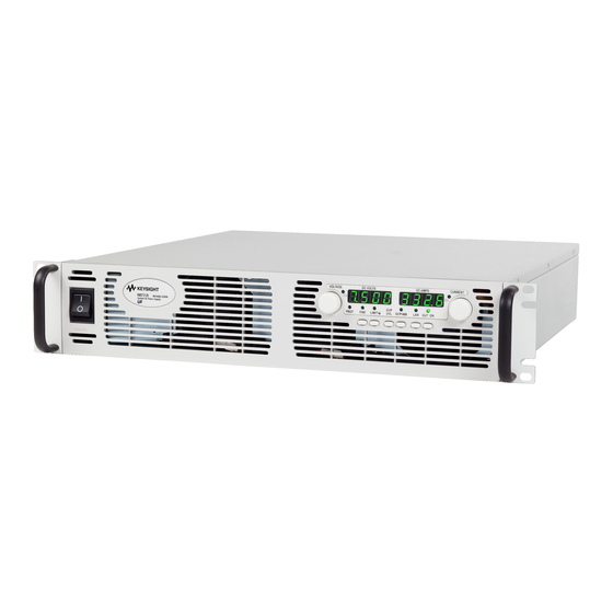
1 Quick Reference The Agilent N8700 DC Power Supplies – At a Glance The Agilent Technologies Series N8700 System DC Power Supplies are general-purpose, 2U (two rack units) high, switching power supplies that are available with a wide variety of output voltage and current ratings. -
Page 9: Programmable Functions
0 – 11A N8742A 0 – 600V 0 – 5.5A Note 1: Minimum output voltage is ≤ 0.2% of the rated output voltage. Note 2: Minimum output current is ≤ 0.4% of the rated output current. Series N8700 User’s Guide... -
Page 10: The Front Panel - At A Glance
Start-Up function: Press and hold the OUT ON button to toggle between the Safe-Start and Auto-Restart modes. The display cycles between SAF and AU7. Releasing the OUT ON button while one of the modes is displayed selects that mode. Series N8700 User’s Guide... - Page 11 9 – LAN indicator Indicates the LAN has been configured and is operating normally. Set another unit on the N8700 unit’s Web home page and the LAN indicator blinks to identify that unit. 10 – LAN button View address: Press the LAN button to view the IP and Ethernet address. The display first scrolls through the four segments of the IP address, followed by the six segments of the Ethernet (EA) address.
-
Page 12: The Rear Panel - At A Glance
SHOCK HAZARD The AC power cable provides a chassis ground through the WARNING ground conductor. Be certain that your power source is three-conductor for single-phase models or four-conductor for 3-phase models with the ground conductor (green/yellow) connected to earth ground. Series N8700 User’s Guide... - Page 13 Down: The output current is programmed by the front panel. programming The output current is programmed by the external resistor. 9 – Enable/Disable control Down: The J1 Enable+/Enable– pins are not active. The J1 Enable+/Enable– pins are active. Series N8700 User’s Guide...
- Page 14 Current Prog. Return Signal return for Pin 10. Referenced internally to pin 12. Pin 24: Current Monitor Output for monitoring the output current. Pin 25: Parallel Output for current balancing in parallel operation. Connected internally to pin 24. Series N8700 User’s Guide...
-
Page 15: Installation
Before getting started, check the list under “Items Supplied” and verify that you have received these items with your instrument. If anything is missing, please contact your nearest Agilent Sales and Service Office. Series N8700 User’s Guide... -
Page 16: General Information
Agilent Sales and Service Office immediately. Refer to Appendix C for more information. Until you have checked out the power supply, save the shipping carton and packing materials in case the unit has to be returned. Series N8700 User’s Guide... -
Page 17: Installing The Unit
Do not operate the power supply in an area where the ambient temperature exceeds +40°C. Agilent N8700 power supplies generate magnetic fields, which may affect the NOTE operation of other instruments. If your equipment is susceptible to magnetic fields, do not position it adjacent to the power supply. -
Page 18: Rack Installation
Do not block the air intake at the front, or the exhaust at the rear of the unit. The Agilent N8700 power supplies can be mounted in a standard 19- inch rack panel or cabinet. They are designed to fit in two rack units (2U) of space. -
Page 19: Connecting The Line Cord
450V, 20 A, 70 °C 4 x 2.5 mm 2.5 m Harmonized 2 Note2 (380-415 VAC nominal) Note 1: 2-wire plus one green/yellow safety ground conductor 2: 3-wire plus one green/yellow safety ground conductor : 10 AWG corresponds to 4mm Series N8700 User’s Guide... - Page 20 208 V, phase- to-phase distribution. phase Disconnect device phase phase Option 400 units wired for nominal AC input Earth 380 – 415 VAC (safety ground) 400 V 3-phase power supply attached to 400 V, phase- to-phase distribution. phase Series N8700 User’s Guide...
- Page 21 Tightening torque: 14 – 16.2 ft-lb (19 – 22 Nm). Refer to the following figure. 3-phase cable (shown) has four conductors. Single-phase cable has three conductors. Series N8700 User’s Guide...
- Page 22 Route the wires inside the cover to prevent pinching while sliding the cover towards the rear panel for attachment. Fasten the cover to the unit using the M3 x 8mm flat head screws provided. Screw tightening torque: 4.8 in-lb (0.54 Nm). Refer to the following figure. Series N8700 User’s Guide...
-
Page 23: Connecting The Load
60 °C. For ambient temeratures other than 30 °C, multiply the above ampacities by the following constants: Temp (°C) Constant Temp (°C) Constant 21-25 1.08 31-35 0.91 26-30 1.00 36-40 0.82 Note 2. Resistance is nominal at 20 °C wire temperature. Series N8700 User’s Guide... - Page 24 Flat washers Spring washer Install the shield after you have finished connecting the load wires. Route the load wires through the openings in the back of the shield. If necessary, use diagonal cutters and remove the Series N8700 User’s Guide...
- Page 25 The connector specifications are as follows: Wire Size: AWG 18 to AWG 10 Stripping Length: 10 mm (0.4 in) Torque: 4.4 – 5.3 in-lb (0.5 – 0.6 Nm) Series N8700 User’s Guide...
- Page 26 Attach the load wires to the notched shield tab using a tie-wrap or equivalent as shown in the following figure. Load wires Series N8700 User’s Guide...
-
Page 27: Output Voltage Sensing
The following figure illustrates the internal connections of the J2 connector. Power Load Supply Rem.sense Load lines, twisted Local sense Error pair, shortest length Amp. Local sense possible. Rem.sense Series N8700 User’s Guide... -
Page 28: Remote Sensing
Turn on the power supply. Load lines. Twisted pair shortest length possible. Load Power Supply Rem.sense Local sense ocal sense Rem.sense Sense lines. Twisted pair or shielded wires. Series N8700 User’s Guide... -
Page 29: Load Considerations
Sense either at the remote distribution terminals or, if one load is more sensitive than the others, directly at the critical load. Distribution terminal Load#1 Power Supply Load#2 Rem.sense Local sense Load#3 ocal sense Rem.sense Series N8700 User’s Guide... -
Page 30: Battery Charging
+ output connection of the power supply. Connect the diode’s cathode to the + battery terminal or external voltage source. Connect the diode’s anode to the + output terminal of the power supply. Series N8700 User’s Guide... -
Page 31: Parallel Connections
As short as possible MASTER Twisted POWER SUPPLY pair J1-25 J1-12 Parallel Common LOAD Curr Prog Curr Prog Rtn J1-8 J1-12 J1-10 J1-23 SLAVE POWER SUPPLY Local Sensing Series N8700 User’s Guide... -
Page 32: Setting Up The Master Unit
The current limit of each unit should be programmed to the desired load current limit divided by the number of parallel units. Series N8700 User’s Guide... -
Page 33: Series Connections
It is recommended that diodes be connected in parallel with each output to prevent reverse voltage during start up sequence or in case one unit shuts down. Each diode should be rated to at least the rated output voltage and output current of the power supply. Series N8700 User’s Guide... - Page 34 The analog programming circuits of these power supplies are referenced to the negative sense (-S) potential. Therefore, the analog voltage circuits used to control each series-connected unit must be separated and floated from each other. Series N8700 User’s Guide...
-
Page 35: J1 Connector Connections
J1. Chapter 3 describes how to configure the J1 connector when using it to program the output voltage and current. Series N8700 User’s Guide... - Page 37 output on/off functions safe-start and auto-restart analog programming of voltage and current front panel locking Refer to chapters 4 and 5 for information on programming your power supply using SCPI commands. Series N8700 User’s Guide...
-
Page 38: Operating The Power Supply Locally
OVP setting. Check to make sure that the output voltage cannot be set higher than the OVP setting. Press the OVP/UVL button again. Rotate the voltage knob and reset the OVP level of the unit to its maximum setting. Series N8700 User’s Guide... - Page 39 Press the OUT ON button to reset the OCP protection. The output should return to its previous setting. Turn the POWER switch off. Remove the short from the +V and –V output terminals. Series N8700 User’s Guide...
-
Page 40: Normal Operation
5 seconds after the adjustment has been completed and then go blank because the output is off. The current knob can be set to coarse or fine resolution. Press the FINE button to select finer resolution. The FINE indicator turns on. Series N8700 User’s Guide... -
Page 41: Protection Functions
Refer to Appendix A for the maximum OVP settings. Use one of the following methods to reset the OVP circuit after it activates. If the condition that caused the over-voltage shutdown is still present, the OVP circuit will turn the output off again. Series N8700 User’s Guide... - Page 42 OUT ON button to reset OCP. With this method, the over- current protection is disabled. If the load current is still higher than the current limit setting, the power supply will only attempt to limit the current at the current limit setting. Series N8700 User’s Guide...
- Page 43 NOTE If the front panel has been locked from the front panel, it cannot be unlocked by SYST:COMM:RLST. Conversely, if the front panel has been locked by SYST:COMM:RLST, it cannot be unlocked from the front panel. Series N8700 User’s Guide...
-
Page 44: Output On/Off Controls
Shut-Off function enables or disables the output according to the signal level or the open/short applied to J1 pin 15. When the output has been disabled by the Shut-Off function, the display shows SO to indicate the output is disabled. Series N8700 User’s Guide... - Page 45 You must also press the OUT ON button or send an OUTPut:PROTection:CLEar command to resume operation. SW1 switch 9 ENA+/ENA– pins Output Display Prot Indicator Down (default) Not active Voltage/Current Opened Blinking Shorted Voltage/Current Series N8700 User’s Guide...
-
Page 46: Power Supply Ok Signal
Power Supply OK signals are referenced to Chassis Common (J1 pins 2 and 3). POWER SUPPLY POWER SUPPLY POWER SUPPLY J1-2,3 J1-16 J1-15 J1-2,3 J1-16 J1-15 J1-2,3 J1-16 J1-15 Supply OK Shut Off Supply OK Shut Off Supply OK Shut Off Series N8700 User’s Guide... -
Page 47: Analog Programming Of Output Voltage And Current
J1 pin 21 Output voltage/ function signal current control Both Down (default) No effect Open Local Either one, or both Up 0 or Short 0~0.6V Analog 1 or Open Open Local CURRENT LIMIT OUTPUT VOLTAGE PROGRAMMING PROGRAMMING Series N8700 User’s Guide... - Page 48 SW1 switch 3 Voltage Programming Current Programming (J1 pin 9) (J1 pin 10) Down (default) 0 – 5V 0 – 5V 0 – 10V 0 – 10V Series N8700 User’s Guide...
- Page 49 0 – 5 kΩ 0 – 10 kΩ 0 – 10 kΩ OUTPUT VOLTAGE CURRENT LIMIT PROGRAMMING PROGRAMMING PROGRAMMING PROGRAMMING RESISTOR RESISTOR OPTIONAL SETS OPTIONAL SETS LOWER LIMIT LOWER LIMIT OPTIONAL SETS OPTIONAL SETS UPPER LIMIT UPPER LIMIT Series N8700 User’s Guide...
- Page 50 J1 pin 11 Voltage Monitor J1 pin 24 Current Monitor 0 – 10V J1 pin 11 Voltage Monitor J1 pin 24 Current Monitor J1 pin 12 is the signal common for J1 pins 11 and 24. Series N8700 User’s Guide...
-
Page 51: Operating The Power Supply Remotely
Programmable Instruments) is a programming language for controlling instrument functions over the GPIB. SCPI is layered on top of the hardware-portion of IEEE 488.2. The same SCPI commands and parameters control the same functions in different classes of instruments. Series N8700 User’s Guide... -
Page 52: Connecting To The Interfaces
4 Operating the Power Supply Remotely Connecting to the Interfaces The Agilent N8700 power supplies support remote interface communication using a choice of three interfaces: GPIB, USB, and LAN. All three interfaces are live at power-on. GPIB Interface For detailed information about GPIB interface connections, refer to the Agilent... - Page 53 The VISA address is: USB0::2391::2055::model-serialnumber::0:INSTR NOTE where 2391 is the Agilent code, 2055 is the N8700 code, model is the 6- character model number, and serialnumber is the 10-character serial number located on the label on the side of the unit.
- Page 54 IP address has been assigned. Press the front panel LAN button to view the IP address. Each Agilent N8700 power supply is shipped with a default hostname with the NOTE format: A-modelnumber-serialnumber where modelnumber is the instrument’s 6-character model number (e.g.
- Page 55 Press the front panel LAN button to view the IP address. Use the Connection Expert utility of the Agilent IO Libraries Suite to add the N8700 power supply and verify a connection. To add the instrument, you can request the Connection Expert to discover the instrument.
- Page 56 These latter methods are a convenient way to communicate with the power supply without using I/O libraries or drivers. Ethernet Connection Monitoring Agilent N8700 power supplies that have the LXI label on the front panel provide Ethernet connection monitoring. With Ethernet connection monitoring, the instrument’s LAN port is continually...
- Page 57 Using Telnet In an MS-DOS Command Prompt box type: telnet hostname 5024 where hostname is the N8700 hostname or IP address, and 5024 is the instrument’s telnet port. You should get a Telnet session box with a title indicating that you are connected to the power supply.
- Page 58 This value is the Internet Protocol (IP) address of the instrument. An IP address is required for all IP and TCP/IP communications with the instrument. An IP Address consists of 4 decimal numbers separated by periods. Each decimal number ranges from 0 through 255. Series N8700 User’s Guide...
- Page 59 Enter the new password in the Enter New field and in the Confirm New field. The password can be up to 12 alpha-numeric characters (letters, numbers, underscore); case insensitive. The first character must be a letter. If the fields are blank, password checking is disabled. Series N8700 User’s Guide...
- Page 60 USB interface or the GPIB interface as previously described. Install the Setup utility on your computer. Run the Setup utility by clicking Start|Programs|Agilent|N8700 Setup Utility. Configure the following LAN address parameters. These are located under the Settings tab. For a description of these parameters, refer to the previous section.
- Page 61 You can also use the Setup utility to view model-specific information about your power supply. Click the Model About tab to view the model number, serial number, active firmware version, backup firmware version, and output ratings. Series N8700 User’s Guide...
-
Page 62: Scpi Commands - An Introduction
For the first command in a message, the path is a null string. For each subsequent command the path is defined as the characters that make up the keywords of the Series N8700 User’s Guide... - Page 63 ABORt<NL> VOLTage 20<NL> VOLTage:TRIGgered MINimum<NL> Colons (:) separate higher-level keywords from lower-level keywords. Use a blank space to separate parameters from keywords. If a command requires more than one parameter, use commas to separate adjacent parameters. Series N8700 User’s Guide...
- Page 64 Three permitted command terminators are: newline (<NL>), which is ASCII decimal 10 or hex 0A. end or identify (<END>) both of the above (<NL><END>). In the examples of this guide, the message terminator is assumed. Series N8700 User’s Guide...
-
Page 65: Parameter Types
<AARD> Arbitrary ASCII Response Data. Permits the return of undelimited 7-bit ASCII. This data type has an implied message terminator. <SRD> String Response Data. Returns string parameters enclosed in double quotes. Series N8700 User’s Guide... - Page 66 Clear. Device Clear also prepares the power supply to accept a new command string. The following statement shows how to send a device clear over the GPIB interface using Agilent BASIC: CLEAR 705 IEEE-488 Device Clear Series N8700 User’s Guide...
-
Page 67: Language Reference
(command) or three letters and a ? (query). They are defined by the IEEE 488.2 standard to perform common interface functions. Common commands are grouped along with the subsystem commands according to the function they perform. Series N8700 User’s Guide... -
Page 68: Scpi Command Summary
:PROTection :STATe <Bool> Enables/disables over-current protection VOLTage [:LEVel] [:IMMediate][:AMPLitude] <NRf+> Sets the output voltage :TRIGgered[:AMPLitude] <NRf+> Sets the triggered output voltage :LIMit :LOW <NRf+> Sets the low-voltage limit :PROTection [:LEVel] <NRf+> Sets the over-voltage protection level Series N8700 User’s Guide... -
Page 69: Common Commands
Saves an instrument state *SRE <NRf> Set service request enable register *SRE? Return service request enable register *STB? Return status byte *TRG Trigger *TST Performs self-test, then returns result *WAI Holds off bus until all device commands done Series N8700 User’s Guide... -
Page 70: Calibration Commands
This command lets you change the calibration password. A new password is automatically stored in nonvolatile memory. If the password is set to 0, password protection is removed and the ability to enter calibration mode is unrestricted. The default password is 0 (zero). Series N8700 User’s Guide... -
Page 71: Measure Commands
Measurement overflows return a reading of 9.91E+37. MEASure[:SCALar]:CURRent[:DC]? MEASure[:SCALar]:VOLTage[:DC]? These queries perform a measurement and return the DC output current in amperes or DC output voltage in volts. Series N8700 User’s Guide... -
Page 72: Output Commands
OUTPut:PON:STATe is AUTO. All conditions that generate the fault must be removed before the latch can be cleared. The output is then restored to the state it was in before the fault condition occurred. Series N8700 User’s Guide... -
Page 73: Source Commands
1.05; whichever is lower. The minimum value is either the value in the table, or the low voltage setting divided by 0.95; whichever is higher. Series N8700 User’s Guide... - Page 74 The maximum setting is the value in the table. An over-voltage condition can be cleared with the Output Protection Clear command after the condition that caused the OVP trip is removed. Model (V rating) 100V 150V 300V 600V Min. protection limit Max. protection limit Series N8700 User’s Guide...
-
Page 75: Status Commands
Data LOGICAL LOGICAL OPER *STB? *SRE<n> *SRE? *ESR? *ESE<n> *ESE? OPERATION STATUS SERVICE CONDITION PTR/NTR EVENT ENABLE REQUEST GENERATION LOGICAL 10 1024 1024 1024 1024 STAT:OPER:COND? STAT:OPER:ENAB <n> STAT:OPER:ENAB STAT:OPER:PTR |:NTR <n> STAT:OPER:PTR |:NTR ? STAT:OPER:EVEN? Series N8700 User’s Guide... - Page 76 (OPER) of the Status Byte register. This bit (bit 7) is the logical OR of all the Operational Event register bits that are enabled by the Status Operation Enable register. The Preset value = 0. Series N8700 User’s Guide...
- Page 77 OV = The output is disabled by the over-voltage protection STATus:QUEStionable:CONDition? This query returns the value of the Questionable Condition register. That is a read-only register, which holds the real-time (unlatched) questionable status of the power supply. Series N8700 User’s Guide...
- Page 78 Clears the Standard Event Status, Operation Status Event, and Questionable Status Event registers Clears the Status Byte and the Error Queue If *CLS immediately follows a program message terminator (<NL>), then the output queue and the MAV bit are also cleared. Series N8700 User’s Guide...
- Page 79 *OPC? prevents processing of all subsequent commands. It can be used at the end of a command line so that the program can monitor the bus for data until it receives the "1" from the Output Queue. Series N8700 User’s Guide...
- Page 80 This command instructs the power supply not to process any further commands until all pending operations are completed. Pending operations are as defined under the *OPC command. *WAI can be aborted only by sending the power supply a Device Clear command. Series N8700 User’s Guide...
-
Page 81: System Commands
ERRORS (see Appendix C for error codes). SYSTem:VERSion? This query returns the SCPI version number to which the instrument complies. The returned value is of the form YYYY.V, where YYYY represents the year and V is the revision number for that year. Series N8700 User’s Guide... - Page 82 This command stores the present state of the power supply to memory locations 0 through 15. All saved instrument states are lost when the unit is turned off. NOTE *TST? This query always returns a zero. Series N8700 User’s Guide...
-
Page 83: Trigger Commands
Only BUS can be selected as the trigger source. *TRG This command generates a trigger when the trigger source is set to BUS. The command has the same affect as the Group Execute Trigger (<GET>) command. Series N8700 User’s Guide... -
Page 85: Programming Examples
You have a royalty-free right to use, modify, reproduce and distribute the example programs (and/or any modified version) in any way you find useful, provided you agree that Agilent Technologies has no warranty, obligations, or liability for any example programs. -
Page 86: Output Programming Example
'1 for on, 0 for off With Instrument ' Send a power reset to the instrument .WriteString "*RST" ' Query the instrument for the IDN string .WriteString "*IDN?" IDN = .ReadString ' Set the voltage .WriteString "VOLT" & Str$(VoltSetting) Series N8700 User’s Guide... - Page 87 ' Check instrument for any errors .WriteString "Syst:err?" ErrString = .ReadString ' give message if there is an error If Val(ErrString) Then MsgBox "Error in instrument!" & vbCrLf & ErrString End If End With End Sub Series N8700 User’s Guide...
-
Page 88: Trigger Programming Example
' amps trigVoltSetting = 5 ' volts trigCurrSetting = 3 ' amps With Instrument ' Send a power reset to the instrument .WriteString "*RST" ' Query the instrument for the IDN string .WriteString "*IDN?" IDN = .ReadString Series N8700 User’s Guide... - Page 89 ' Check instrument for any errors .WriteString "Syst:err?" ErrString = .ReadString ' Give message if there is an error If Val(ErrString) Then MsgBox "Error in instrument!" & vbCrLf & ErrString End If End With End Sub Series N8700 User’s Guide...
-
Page 91: Appendix A Specifications
Outline Diagram ....................96 This chapter lists the specifications and supplemental characteristics of the Agilent N8700 power supplies. A dimensional line drawing of the unit is included at the end of the chapter. Unless otherwise noted, specifications are warranted over the ambient temperature range of 0°to 40°C. -
Page 92: Performance Specifications
Minimum voltage is guaranteed to a maximum of 0.2% of the rated output voltage. NOTE 1 Minimum current is guaranteed to a maximum of 0.4% of the rated output current. 20MHz NOTE 2 From 5Hz - 1MHz NOTE 3 Series N8700 User’s Guide... -
Page 93: Supplemental Characteristics
Voltage 3.3kW units 100 PPM/°C from rated output voltage Voltage 5kW units 100 PPM/°C from rated output voltage Current 3.3kW units 200 PPM/°C from rated output current Current 5kW units 100 PPM/°C from rated output current Series N8700 User’s Guide... - Page 94 Statements provided to comply with requirements of the German Sound Emission Directive, from 18 January 1991: Sound Pressure Lp <70 dB(A), * At Operator Position, * Normal Operation, * According to EN 27779 (Type Test). Schalldruckpegel Lp <70 dB(A) * Am Arbeitsplatz, * Normaler Betrieb, * Nach EN 27779 (Typprüfung). Series N8700 User’s Guide...
- Page 95 3-phase models: 0.94 at nominal input and rated output power 5kW units Efficiency 82% – 88% 3.3kW units 83% – 88% 5kW units Inrush Current < 50A Single-phase models < 50A 3-phase, 200V models < 20A 3-phase, 400V models Series N8700 User’s Guide...
-
Page 96: Outline Diagram
92.0mm 92.0mm 442.5+/-1.0mm Bus-Bar Detail Output Cover Detail 8V to 100V Models 8V to 100V Models 5.0mm 30.0mm 10.5mm 50.0mm 108.0mm NOTES: Holes marked “A” are for chassis slide mounting. Use only screws designated #10-32x0.38” maximum. Series N8700 User’s Guide... -
Page 97: Appendix B - Verification And Calibration
This appendix also includes calibration procedures for the Agilent N8700 power supplies. Instructions are given for performing the procedures from a controller over the GPIB. Perform the verification tests before calibrating your power supply. If the power... -
Page 98: Equipment Required
1156DT-3Y, 0-280V, 50A, 24.2 KVA or equivalent Test Records Test records for each power supply model are provided after the test procedure sections. 3.3 kW test records are provided followed by the 5 kW test records. Series N8700 User’s Guide... -
Page 99: Measurement Techniques
-LS -S Load Resistor DC voltmeter, DC voltmeter, Current scope, or scope, or shunt rms voltmeter rms voltmeter Differential amplifier Electronic load Electronic load output or resistor or resistor 50 ohm termination input Scope or rms voltmeter Series N8700 User’s Guide... - Page 100 Open the load and record the voltage reading from the DVM again. The difference between the DVM readings in steps 4 and 5 is the load effect, which should not exceed the value listed in the test record for the appropriate model under CV Load Effect. Series N8700 User’s Guide...
- Page 101 AC coupling. Set the oscilloscope’s time base to 5 ms/div, and the vertical scale to 10 mV/div. Turn the bandwidth limit on (usually 20 or 30 MHz), and set the sampling mode to peak detect. Series N8700 User’s Guide...
- Page 102 Record the voltage at time “t” in the performance test record under Transient Response. Loadi ng T ransi ent tttt U nl oadi ng T ransi ent Series N8700 User’s Guide...
- Page 103 With the electronic load in CV mode, set it for the output’s full- scale voltage. The CC annunciator on the front panel must be on. If it is not, adjust the load so that the voltage drops slightly. Series N8700 User’s Guide...
- Page 104 The difference between the DVM reading in steps 6 and 8 is the source effect, which should not exceed the value listed in the test record for the appropriate model under CC Source Effect. 10 Return the voltage and current settings to zero. Series N8700 User’s Guide...
- Page 105 Current Programming & Readback, High Current 400A, 8V CC Load Effect, Source Effect 400A, 8V N8731A Load Requirements Current shunt 0.0005 500 A Agilent N3300 Electronic load modules 6 – N3306A Fixed Resistor for CV Ripple and Noise 0.02 3.5 kW Series N8700 User’s Guide...
- Page 106 Current Programming & Readback, High Current 330A, 10V CC Load Effect, Source Effect 330A, 10V N8732A Load Requirements Current shunt 0.0005 500 A Agilent N3300 Electronic load modules 6 – N3306A Fixed Resistor for CV Ripple and Noise 0.03 3.5 kW Series N8700 User’s Guide...
- Page 107 Current Programming & Readback, High Current 220A, 15V CC Load Effect, Source Effect 220A, 15V N8733A Load Requirements Current shunt 0.001 300A Agilent N3300 Electronic load modules 6 – N3306A Fixed Resistor for CV Ripple and Noise 0.068 3.5 kW Series N8700 User’s Guide...
- Page 108 Current Programming & Readback, High Current 165A, 20V CC Load Effect, Source Effect 165A, 20V N8734A Load Requirements Current shunt 0.001 300 A Agilent N3300 Electronic load modules 6 – N3306A Fixed Resistor for CV Ripple and Noise 0.21 3.5 kW Series N8700 User’s Guide...
- Page 109 Current Programming & Readback, High Current 110A, 30V CC Load Effect, Source Effect 110A, 30V N8735A Load Requirements Current shunt 0.01 100 A Agilent N3300 Electronic load modules 6 – N3306A Fixed Resistor for CV Ripple and Noise 0.27 3.5 kW Series N8700 User’s Guide...
- Page 110 Current Programming & Readback, High Current 85A, 40V CC Load Effect, Source Effect 85A, 40V N8736A Load Requirements Current shunt 0.01 100 A Agilent N3300 Electronic load modules 6 – N3306A Fixed Resistor for CV Ripple and Noise 0.47 3.5 kW Series N8700 User’s Guide...
- Page 111 Current Programming & Readback, High Current 55A, 60V CC Load Effect, Source Effect 55A, 60V N8737A Load Requirements Current shunt 0.01 100 A Agilent N3300 Electronic load modules 6 – N3306A Fixed Resistor for CV Ripple and Noise 3.5 kW Series N8700 User’s Guide...
- Page 112 Current Programming & Readback, High Current 42A, 80V CC Load Effect, Source Effect 42A, 80V N8738A Load Requirements Current shunt 0.01 100 A Agilent N3300 Electronic load modules 7 – N3305A Fixed Resistor for CV Ripple and Noise 3.5 kW Series N8700 User’s Guide...
- Page 113 Current Programming & Readback, High Current 33A, 100V CC Load Effect, Source Effect 33A, 100V N8739A Load Requirements Current shunt 0.01 100 A Agilent N3300 Electronic load modules 7 – N3305A Fixed Resistor for CV Ripple and Noise 3.5 kW Series N8700 User’s Guide...
- Page 114 Current Programming & Readback, High Current 22A, 150V CC Load Effect, Source Effect 22A, 150V N8740A Load Requirements Current shunt 0.01 100 A Agilent N3300 Electronic load modules 7 – N3305A Fixed Resistor for CV Ripple and Noise 3.5 kW Series N8700 User’s Guide...
- Page 115 11A, 300V N8741A Load Requirements Current shunt 15 A Use fixed resistor instead of load modules 27.3 3.5 kW (or Amrel 5KW 600V 300A electronic load) Fixed Resistor for CV Ripple and Noise 27.3 3.5 kW Series N8700 User’s Guide...
- Page 116 CC Load Effect, Source Effect 5.5A, 600V N8742A Load Requirements Current shunt 15 A Use fixed resistor instead of load modules 3.5 kW (or Amrel 5KW 600V 300A electronic load) Fixed Resistor for CV Ripple and Noise 3.5 kW Series N8700 User’s Guide...
- Page 117 Current Programming & Readback, High Current 250A, 20V CC Load Effect, Source Effect 250A, 20V N8754A Load Requirements Current shunt 0.001 300 A Agilent N3300 Electronic load modules 9 – N3306A Fixed Resistor for CV Ripple and Noise 0.08 5.5 kW Series N8700 User’s Guide...
- Page 118 Current Programming & Readback, High Current 170A, 30V CC Load Effect, Source Effect 170A, 30V N8755A Load Requirements Current shunt 0.001 300 A Agilent N3300 Electronic load modules 9 – N3306A Fixed Resistor for CV Ripple and Noise 0.176 5.5 kW Series N8700 User’s Guide...
- Page 119 Current Programming & Readback, High Current 125A, 40V CC Load Effect, Source Effect 125A, 40V N8756A Load Requirements Current shunt 0.001 300 A Agilent N3300 Electronic load modules 9 – N3306A Fixed Resistor for CV Ripple and Noise 0.32 5.5 kW Series N8700 User’s Guide...
- Page 120 Current Programming & Readback, High Current 85A, 60V CC Load Effect, Source Effect 85A, 60V N8757A Load Requirements Current shunt 0.01 100 A Agilent N3300 Electronic load modules 9 – N3306A Fixed Resistor for CV Ripple and Noise 0.705 5.5 kW Series N8700 User’s Guide...
- Page 121 Current Programming & Readback, High Current 65A, 80V CC Load Effect, Source Effect 65A, 80V N8758A Load Requirements Current shunt 0.01 100 A Agilent N3300 Electronic load modules 11 – N3305A Fixed Resistor for CV Ripple and Noise 1.23 5.5 kW Series N8700 User’s Guide...
- Page 122 Current Programming & Readback, High Current 50A, 100V CC Load Effect, Source Effect 50A, 100V N8759A Load Requirements Current shunt 0.01 100 A Agilent N3300 Electronic load modules 11 – N3305A Fixed Resistor for CV Ripple and Noise 5.5 kW Series N8700 User’s Guide...
- Page 123 Current Programming & Readback, High Current 34A, 150V CC Load Effect, Source Effect 34A, 150V N8760A Load Requirements Current shunt 0.01 100 A Agilent N3300 Electronic load modules 11 – N3305A Fixed Resistor for CV Ripple and Noise 5.5 kW Series N8700 User’s Guide...
- Page 124 17A, 300V N8761A Load Requirements Current shunt 15 A Use fixed resistor instead of load modules 17.6 5.5 kW (or Amrel 5KW 600V 300A electronic load) Fixed Resistor for CV Ripple and Noise 17.6 5.5 kW Series N8700 User’s Guide...
- Page 125 8.5A, 600V N8762A Load Requirements Current shunt 15 A Use fixed resistor instead of load modules 70.6 5.5 kW (or Amrel 5KW 600V 300A electronic load) Fixed Resistor for CV Ripple and Noise 70.6 5.5 kW Series N8700 User’s Guide...
-
Page 126: Calibration
Step 1. Connect the Agilent 3458A voltage input to the output. Step 2. Enable voltage calibration mode. *RST OUTP ON CAL:STAT ON Step 3. Set the current limit high enough to allow unrestricted voltage programming. ISET 0.5 Step 4. Select voltage calibration. CAL:VOLT Series N8700 User’s Guide... - Page 127 Step 6. Calculate the shunt current (I=V/R) and enter the data. CAL:DATA <data> Step 7. Select the second current calibration point. CAL:LEV P2 *OPC? Step 8. Calculate the shunt current (I=V/R) and enter the data. CAL:DATA <data> Step 9. Exit calibration mode. CAL:STAT OFF Series N8700 User’s Guide...
-
Page 129: Appendix C Service
..................130 Error Messages ....................132 Recycling Plastic Components ..............136 This chapter discusses the procedures involved for returning a failed instrument to Agilent Technologies for service or repair. A procedure is included for diagnosing specific symptoms. Series N8700 User’s Guide... -
Page 130: Types Of Service Available
Repackaging for Shipment If the unit is to be shipped to Agilent Technologies for service or repair, be sure to: Attach a tag to the unit identifying the owner and indicating the ... - Page 131 2. Front panel controls are nonfunctional. Is the power supply in Local Lockout mode? Turn off the POWER switch and wait until the display turns off. Turn on the POWER switch and press the REM/LOC button. Series N8700 User’s Guide...
-
Page 132: Error Messages
Attempted to set the over-voltage protection below the voltage setting. VOLT setting conflicts with VOLT:LIM:LOW setting Attempted to program the voltage below the under-voltage limit setting. VOLT:LIM:LOW setting conflicts with VOLT setting Attempted to set the under-voltage limit above the voltage setting Series N8700 User’s Guide... - Page 133 A suffix was incorrectly specified for a numeric parameter. Suffix too long −134 The suffix contains more than 12 characters. Suffix not allowed −138 A suffix is not supported for this command. Character data error −140 Generic character data error Series N8700 User’s Guide...
- Page 134 The device has insufficient memory to perform the requested operation. Lists not same length −226 One or more lists are not the same length. Data corrupt or stale −230 Possible invalid data. A new reading was started but not completed. Series N8700 User’s Guide...
- Page 135 A condition causing an unterminated query error occurred. Query DEADLOCKED −430 A condition causing a deadlocked query error occurred. Query UNTERMINATED after indefinite response −440 A query was received in the same program message after a query indicating an indefinite response was executed. Series N8700 User’s Guide...
-
Page 136: Recycling Plastic Components
LEXAN 243R NYLON 6/6 Line cord strain relief (qty 1) Polyamide PA Display insulator – clear (qty 1) LEXAN FR60 Cover insulator – clear (qty 1) LEXAN FR60 Chassis insulator – clear (qty 1) LEXAN FR60 Series N8700 User’s Guide... -
Page 137: Appendix D Compatibility
The Agilent N8700 power supplies are programmatically compatible with the Agilent 603xA power supplies. This means that you can remotely program the Agilent N8700 power supplies using the same commands that are used to program the 603xA power supplies. Do not mix Compatibility with SCPI commands in the same program. This will CAUTION result in unpredictable instrument behavior. -
Page 138: Differences - In General
Sending a second query without reading the response to the first will generate an error. Model number queries will only return the N8700 model numbers. Status functions Serial Poll will be controlled by the SCPI status model and will not act like a 603xA power supply. -
Page 139: Compatibility Command Summary
Index Compatibility Command Summary The following table documents the compatibility commands that the Agilent N8700 power supplies support. All compatibility commands are accepted; however, some commands do nothing. Compatibility Command Description Similar SCPI Command ASTS? Queries the accumulated status (ASTS). The response represents the... - Page 140 CV – constant voltage CC – constant current OR – overrange OV – overvoltage tripped OT – overtemperature tripped AC – AC line voltge overage.dropout FOLD – foldback tripped ERR – programming error RI – remote inhibit tripped Series N8700 User’s Guide...
-
Page 141: Index
............67 current readback accuracy ..........103 *CLS ................. 78 current shunt ..............99 *ESE ................. 79 CV/CC crossover ............... 41 *ESR? ................79 CV/CC signal ..............41 *IDN? ................82 *OPC ................79 Series N8700 User’s Guide... - Page 142 INIT .................. 83 INIT CONT ..............83 inspection ................16 OCP ..................11 IO ..................52 OPER ..................80 IP Address ................58 operating checklist ............130 items supplied ..............16 optional commands ............62 Series N8700 User’s Guide...
- Page 143 RQS ..................80 Telnet ................57, 60 SAF ..................10 transient recovery time ........... 102 safe-start ................44 trigger commands .............. 83 safety ................3, 17 TRIG ................. 83 SCPI TRIG SOUR ..............83 command completion ........... 66 Series N8700 User’s Guide...
- Page 144 ............42 USB ID string ..............53 USB interface ..............53 warning .................. 3 UUL ..................11 Web server ................56 UVL ..................11 web URL’s ................4 wire sizes ................23 verification ................97 Series N8700 User’s Guide...
- Page 145 Manual Updates The following updates have been made to this manual since its publication date. 9/28/10 Information about battey charging has been added to page 30. Information about parallel connections has been updated on pages 31 and 32. 2/28/11 Text changes have been made to the single-phase distribution figure on page 20, and to the Note on page 21.
Need help?
Do you have a question about the N8700 and is the answer not in the manual?
Questions and answers