Table of Contents
Advertisement
Advertisement
Table of Contents

Related Manuals for Samsung SNB-5003


Summary of Contents for Samsung SNB-5003
-
Page 1: Network Camera
NETWORK CAMERA SNB-5003/SNB-5004 User Manual SND-5083/SND-5084... - Page 2 Disclaimer Samsung Techwin makes the best to verify the integrity and correctness of the contents in this document, but no formal guarantee shall be provided. Use of this document and the subsequent results shall be entirely on the user’s own responsibility.
-
Page 3: Important Safety Instructions
overview important Safety inStructionS 1. Read these instructions. 2. Keep these instructions. 3. Heed all warnings. 4. Follow all instructions. 5. Do not use this apparatus near water. 6. Clean only with dry cloth. 7. Do not block any ventilation openings, Install in accordance with the manufacturer’s instructions. -
Page 4: Explanation Of Graphical Symbols
overview warninG TO REDUCE THE RISK OF FIRE OR ELECTRIC SHOCK, DO NOT EXPOSE THIS PRODUCT TO RAIN OR MOISTURE. DO NOT INSERT ANY METALLIC OBJECT THROUGH THE VENTILATION GRILLS OR OTHER OPENNINGS ON THE EQUIPMENT. Apparatus shall not be exposed to dripping or splashing and that no objects filled with liquids, such as vases, shall be placed on the apparatus. - Page 5 class construction An apparatus with CLASS construction shall be connected to a MAINS socket outlet with a protective earthing connection. Battery Batteries(battery pack or batteries installed) shall not be exposed to excessive heat such as sunshine, fire or the like. Disconnection Device Disconnect the main plug from the apparatus, if it’s defected.
- Page 6 overview Please read the following recommended safety precautions carefully. y Do not place this apparatus on an uneven surface. y Do not install on a surface where it is exposed to direct sunlight, near heating equipment or heavy cold area. y Do not place this apparatus near conductive material.
-
Page 7: Table Of Contents
Important Safety Instructions Product Features Recommended PC Specifications Recommended Micro SD/SDHC/ SDXC Memory Card Specifications What’s Included At a Glance (SNB-5003) At a Glance (SNB-5004) At a Glance (SND-5083) At a Glance (SND-5084) iNSTALLATioN & Mounting the Lens CoNNeCTioN... -
Page 8: Web Viewer
overview web vieweR Connecting to the Camera Login Installing Silverlight Runtime Installing STW WebViewer Plugin Using the Live Screen Playing the recorded video SeTup SCReeN Setup Video & Audio Setup Network Setup Event Setup System Setup AppeNDix Specification Product Overview Troubleshooting Open Source Announcement 8_ overview... -
Page 9: Product Features
proDuct featureS • HD video Quality • multi-Streaming This network camera can display videos in different resolutions and qualities simultaneously using different CODECs. • web Browser-based monitoring Using the Internet web browser to display the image in a local network environment. •... -
Page 10: Sdxc Memory Card Specifications
overview recommenDeD pc SpecificationS • CPU : Intel Core 2 Duo 2.4 GHz or higher (for using 1280x1024 30 fps) Intel Core i7 2.8 GHz or higher (for using 1280x1024 60 fps) Web Plug-in is optimized to SSE 4.1 Instruction Set. •... - Page 11 Please check if your camera and accessories are all included in the product package. Appearance Item Name Quantity Description Model Name SNB-5003 or SNB-5004 or Camera SND-5083 or SND-5084 SNB-5003/ Instruction book, SNB-5004/ Installer S/W CD, SND-5083/ CMS S/W DVD...
- Page 12 Appearance Item Name Quantity Description Model Name Used to install the C Mount SNB-5003/ C Mount Adapter camera lens SNB-5004 Automatic Iris Lens Useful for camera lens SNB-5003/ Connector installation SNB-5004 SNB-5003/ 6-position Terminal Block Used for alarm in/out terminals...
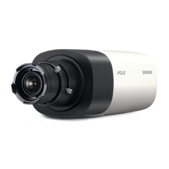
- Page 13 GLance (SnB-5003) front Side Item Description Used to fix the camera on a mounting bracket. The screw size : It is the specification for the screws used to fasten the Mounting Bracket camera to the support. Screw Hole 1/4"...
- Page 14 overview rear Side Item Description Micro SD Memory Compartment for the Micro SD memory card. Card Compartment AUDIO OUT Used to connect to speakers. Audio terminal AUDIO IN Used to connect to a microphone. The button restores all camera settings to the factory default. Press and hold for about 5 seconds to reboot the system.
- Page 15 Item Description Power Port Used to plug the power cable. Network Port Used to connect the PoE or Ethernet cable for network connection. Used to connect the alarm input sensor or external day/ ALARM IN night sensor. ALARM OUT Used to connect the alarm output signal. Alarm I/O Port Used for earth-grounding.
- Page 16 overview at a GLance (SnB-5004) front Side Item Description Used to fix the camera on a mounting bracket. The screw size : It is the specification for the screws used to fasten the Mounting Bracket camera to the support. Screw Hole 1/4"...
- Page 17 rear Side Item Description Micro SD Memory Compartment for the Micro SD memory card. Card Compartment AUDIO OUT Used to connect to speakers. Audio terminal AUDIO IN Used to connect to a microphone. The button restores all camera settings to the factory default. Press and hold for about 5 seconds to reboot the system.
- Page 18 overview Item Description Lightning protective Used to discharge the lightning current safely outside in order to protect the grounding port camera. Power Port Used to plug the power cable. Network Port Used to connect the PoE or Ethernet cable for network connection. Used to connect the alarm input sensor or external day/ ALARM IN night sensor.
- Page 19 at a GLance (SnD-5083) appearance Item Description Dome cover Case cover used to protect the lens and the main unit. Camera Case Housing part that covers the camera body. English _19...
- Page 20 overview components jk l 20_ overview...
- Page 21 Item Description Internal Cover It is a cover to protect the main body. Lens Lens for the camera. Focus Adjusting Turn it left and right to adjust the lens focus and rotate it clockwise to fix it. Lever Zoom Adjusting It can be used to adjust or fix the lens zoom.
- Page 22 overview at a GLance (SnD-5084) appearance Item Description Dome cover Case cover used to protect the lens and the main unit. Camera Case Housing part that covers the camera body. 22_ overview...
- Page 23 components ij k English _23...
- Page 24 overview Item Description Internal Cover It is a cover to protect the main body. Lens Lens for the camera. Zoom in (Tele) Zoom out (Wide) Zoom/Focus Control Focusing on a near object (Near) Button Focusing on a far object (Far) Focus Control Press this button for automatic focus control.
- Page 25 & connection mountinG tHe LenS (SnB-5003/SnB-5004) Disconnect the power before proceeding. The C lens and CS lens are not included in the product package. It is recommended that megapixel lens are use on this camera to optimise performance. mounting the cS lens on a camera Turn the CS lens clockwise to attach it.
-
Page 26: Connecting The Auto Iris Lens Connector
installation & connection connecting the auto iris Lens connector Plug the iris connector of the lens in the camera connecting groove. focusing Select a target to film, turn the zoom lever of the lens to adjust the magnification and then focus the lens so that target is clearly displayed. - Page 27 inStaLLation (SnD-5083/SnD-5084) precautions before installation Ensure you read out the following instructions before installing the camera: • It must be installed on the area (ceiling or wall) that can withstand 5 times the weight of the camera including the installation bracket. •...
- Page 28 installation & connection installation 1. Attach the installation template to the selected area and punch 3 holes as shown in the figure. 2. Use the 2 supplied screws to fix the camera to the 2 punched holes. Set the <FRONT TOP> mark imprinted on the camera to face the direction of camera monitoring.
-
Page 29: Adjusting The Monitoring Direction
adjusting the monitoring direction for the camera (SnD-5083/ SnD-5084) Tilt Lens rotation ` adjusting the monitoring direction You can adjust the camera direction only when the camera is fixed on the ceiling. Where, rotating the camera unit to the left or right is called Pan, adjusting the tilt is called Tilt, and turning the lens on its axis is called Rotation. - Page 30 Do not insert the Micro SD memory card while it’s upside down by force. Otherwise, it may damage the Micro SD memory card. inserting a micro SD memory card Push the Micro SD memory card in the direction of the arrow shown in the diagram. <SNB-5003/SNB-5004> <SND-5083/SND-5084> 30_ installation & connection...
-
Page 31: Removing A Micro Sd Memory Card
Gently press down on the exposed end of the memory card as shown in the diagram to eject the memory card from the slot. <SNB-5003/SNB-5004> <SND-5083/SND-5084> Pressing too hard on the Micro SD memory card can cause the card to shoot out uncontrollably from the slot when released. - Page 32 installation & connection memory carD information (not incLuDeD) what is a memory card? The memory card is an external data storage device that has been developed to offer an entirely new way to record and share video, audio, and text data using digital devices. Selecting a memory card that’s suitable for you Your camera supports Micro SD/SDHC/SDXC memory cards.
-
Page 33: Connecting With Other Device
connectinG witH otHer Device Monitor to install Grounding cable Power Ethernet Monitor to install Ethernet Power The CVBS out terminal of the product is provided for easier installation, and is not recommended for monitoring purposes. English _33... -
Page 34: Ethernet Connection
& connection ethernet connection Connect the Ethernet cable to the local network or to the Internet. power Supply (SnB-5003/SnB-5004) Use the screwdriver to connect each line (+, –) of the power cable to the corresponding power port of the camera. - Page 35 Max Distance 100M PoE Support IEEE 802.3af Grounding the product (SnB-5003/SnB-5004) Connect the ground wire to the ground terminal which is located above the power input terminal by using a screwdriver. Grounding protects the product from a surge or lightning.
- Page 36 installation & connection connecting to audio input/output Speaker Microphone Microphone Microphone Network Speaker Speaker Microphone Speaker Speaker Microphone 36_ installation & connection...
- Page 37 • audio out : Mono signal line output (Max.2.4 Vpp) • Line out impedance : 600Ω connecting to the i/o port box (SnB-5003/SnB-5004) Connect the Alarm I/O signal to the corresponding port of the rear port box. • ALARM IN : Used to connect the alarm input sensor or external day/night sensor.
- Page 38 & connection connecting an external rS-485 device (SnB-5003/SnB-5004) Connect the camera with an external device using the [rS-485 +, -] ports. You can control the pan/tilt operations of the camera via RS-485 communications. The GND connection is recommended for RS-485 communications. If you encounter a communication failure, connect the GND pin as appropriate to correct the GND level between camera and external device.
- Page 39 Refer to the alarm out connection diagram below when connecting devices that exceed the voltage and current specifications. alarm out wiring Diagram (SnB-5003/SnB-5004) External connection Inside of the camera DC 5V or 3.3V...
-
Page 40: Connecting The Camera Directly
network connection and setup You can set up the network settings according to your network configurations. connectinG tHe camera DirectLy to LocaL area networKinG connecting to the camera from a local pc in the Lan 1. Launch an Internet browser on the local PC. 2. -
Page 41: Connecting The Camera Directly To A Dhcp
connectinG tHe camera DirectLy to a DHcp BaSeD DSL/caBLe moDem INTERNET DSL/Cable Modem Camera External Remote PC DDNS Server (Data Center, KOREA) 1. Connect the user PC directly with the network camera. 2. Run the IP Installer and change the IP address of the camera so that you can use the web browser on your desktop to connect to the Internet. - Page 42 network connection and setup connectinG tHe camera DirectLy to a pppoe moDem INTERNET PPPoE Modem Camera External Remote PC DDNS Server (Data Center, KOREA) 1. Connect the user PC directly with the network camera. 2. Run the IP Installer and change the IP address of the camera so that you can use the web browser on your desktop to connect to the Internet.
-
Page 43: Connecting The Camera To A Broadband Router
connectinG tHe camera to a BroaDBanD router witH tHe pppoe/caBLe moDem This is for a small network environment such as homes, SOHO and ordinary shops. Camera INTERNET PPPoE or PPPoE or Broadband Cable Modem Cable Modem Router External Remote PC Camera DDNS Server (Data Center, KOREA) -
Page 44: Buttons Used In Ip Installer
network connection and setup ButtonS uSeD in ip inStaLLer e f g Item Description Model name of the connected camera. Device Name Click the column to sort the list by model name. However, search will be stopped if clicked during the search. Alias This function is not currently implemented. -
Page 45: Static Ip Setup
Exits the IP Installer program. For the IP installer, use only the installer version provided in the installation CD or use the latest one if available. You can download the latest version from the Samsung web site (www.samsungcctv.com). Static ip Setup manual network Setup Run <ip installer_v2.XX.exe>... - Page 46 network connection and setup 3. In the <address> pane, provide the necessary information. • MAC (Ethernet) Address : The MAC address imprinted on the camera label is automatically displayed and requires no user setting. IP related parameters can be set only when DHCP is not checked.
- Page 47 if using a Broadband router • IP Address : Enter an address falling in the IP range provided by the Broadband Router. ex) 192.168.1.2~254, 192.168.0.2~254, 192.168.XXX.2~254 • Subnet Mask : The <Subnet mask> of the Broadband Router will be the <Subnet mask>...
-
Page 48: Auto Network Setup
network connection and setup auto network Setup Run <ip installer_v2.XX.exe> to display the camera search list. At the initial startup, both [auto Set] and [manual Set] will be grayed out. For cameras found with the IPv6 setting, these buttons will be grayed out as the cameras do not support this function. -
Page 49: Dynamic Ip Setup
Dynamic ip Setup Dynamic ip environment Setup • Example of the Dynamic IP environment - If a Broadband Router, with cameras connected, is assigned an IP address by the DHCP server - If connecting the camera directly to modem using the DHCP protocols - If IPs are assigned by the internal DHCP server via the LAN checking the Dynamic ip 1. -
Page 50: Port Range Forward (Port Mapping
network connection and setup port ranGe forwarD (port mappinG) Setup If you have installed a Broadband Router with a camera connected, you must set the port range forwarding on the Broadband Router so that a remote PC can access the camera in it. manual port range forwarding 1. - Page 51 Port forwarding can be done without additional router setup if the router supports the UPnP (Universal Plug and Play) function. After connecting the network camera, set <Quick connect> of <Samsung DDNS> to <On> in the “Setup Network DDNS” menu.
-
Page 52: Setup Connecting To The Camera From A
network connection and setup connectinG to tHe camera from a SHareD LocaL pc 1. Run the IP Installer. It will scan for connected cameras and display them as a list. 2. Double-click a camera to access. The Internet browser starts and connects to the camera. -
Page 53: Connecting To The Camera
web viewer connectinG to tHe camera normally, you would 1. Launch the Internet browser. 2. Type the IP address of the camera in the address bar. ex) • IP address (IPv4) : 192.168.1.100 http://192.168.1.100 - the Login dialog should appear. •... - Page 54 To register your device to the <DDnS> server, visit www.samsungipolis.com and register your device first, and then set the Web Viewer’s <network> - <DDnS> to <Samsung DDnS>, as well as providing <product iD> that had been used for DDNS registration.
- Page 55 LoGin Whenever you access the camera, the login window appears. Enter the User ID and password to access the camera. 1. Enter “admin” in the <user name> input box. The administrator ID, “admin”, is fixed and can not be changed. 2.
-
Page 56: Installing Silverlight Runtime
web viewer inStaLLinG SiLverLiGHt runtime If your PC has not installed Silverlight Runtime or has just installed an old runtime version, you will be redirected to the Silverlight Runtime installation page automatically when accessing the web viewer. to install on windows oS 1. - Page 57 to install on mac oS 1. Run the file trailing with “.dmg”. 2. Run the install package file automatically created, ending with “.pkg”. 3. Click <continue>. 4. Select your language on the language selection screen, and click <continue>. English _57...
- Page 58 web viewer 5. Click <agree>. 6. Click <install>. 7. Enter the password of the account currently logged in, and click <install Software> and continue. 8. Once completed, click <close>. 58_ web viewer...
- Page 59 inStaLLinG Stw webviewer pLuGin If connecting to a camera for the first time, you will see the installation message. Then, install the required WebViewer Plugin to access the camera and control the video from it in real time. 1. When the monitoring page is accessed for the very first time, the installation page is displayed.
- Page 60 web viewer 5. Click [oK]. The old version of Web Viewer Plug-in is deleted. 6. Click [install] to begin installation of the Web Viewer Plug-in. 7. Click [finish]. STW Web Viewer Plug-in installation is completed. 60_ web viewer...
-
Page 61: Using The Live Screen
uSinG tHe Live Screen Item Description Monitoring Move to the monitoring screen. Playback Switch to the monitoring screen that plays recording data in the Micro SD memory. Setup Move to the Setup screen. Displays the Live video on the screen. Viewer Screen You can use the mouse wheel to activate the digital zooming in Viewer screen. -
Page 62: To Capture The Snapshot
Connect the external PTZ to the RS-485 terminal and control the PTZ camera lens direction with the arrow keys. External PTZ Only for SNB-5003/SNB-5004. The pan/tilt operations will be enabled only if the camera is connected to a pan/ tilt-compliant receiver. - Page 63 )] icon to enable it again. to use microphone Click [mic ( )] icon to activate the microphone. to control the ptZ (SnB-5003/SnB-5004) 1. Press the [ptZ ( )] tab. 2. When the PTZ icon appears on the screen, use the direction buttons to adjust the camera angle, zoom factor or focus to your preference.
- Page 64 web viewer pLayinG tHe recorDeD viDeo Before you can play the video, you must configure the record settings. For details on record settings, refer to “Storage”. (page 103) name of event search screen and its function Item Description Set the search date and time from the data saved in the Micro SD memory Search range setting card.
-
Page 65: To Play The Content After Searching By Event
to play the content after searching by event 1. Click the [playback ( )] button. 2. Specify the start time and end time of your search. 3. Select an event type for your search within the specified period. 4. Click the [event search] button. The search results will be displayed in the list. - Page 66 web viewer name of time search screen and its function Item Description Time bar The section in the specific period is played by moving the time bar. Set the search date using the calendar. Search date setting Dates for which there is video in the Micro SD memory card are displayed within the boxes on the calendar.
-
Page 67: To Play After Searching By Time
to play after searching by time 1. Click [time Search ( 2. Click a desired date in the calendar. The video on the specified date will be played. 3. If the video playback is stopped, select a time and click [play ( The video on the selected time will be played. - Page 68 web viewer to back up the searched video 1. During playback, click [ ] on the scene to back up. The scheduling window for backup start and end time appears. 2. Click [ ] button. The Save As window appears. 3.
- Page 69 to play an avi file The AVI file does not contain the recording time data. 1. Separate the micro SD memory card from the camera. Before separating the micro SD memory card, set the <Device> to <Off> in the “Setup Event ...
-
Page 70: Video Profile
setup screen Setup You can configure the video & audio, network, event and system settings of the camera in the network. 1. In the Live screen, click [ Setup ( ) ] . 2. The Setup screen appears. Microsoft Silverlight 5.0 or higher is required to be installed on the PC for setup pages that provide preview video. - Page 71 • E-mail/FTP profile : Video profile to be transferred to the specified email or FTP site. Only the MJPEG codec can be set as the E-mail/FTP profile. • Record profile : This is the profile that is applied to video recording. •...
-
Page 72: To Add/Change The Video Profile
setup screen to add/change the video profile The profile setup can be added or modified to accommodate various profiles depending on the recording conditions. 1. Select one from the <video profile> options. 2. Provide the name and select a codec. 3. - Page 73 • Encoding priority : You can set the video transfer method to Framerate or Compression. • GOV length : It specifies the distance (in terms of number of frames) between two consecutive I-Frames in a video sequence when H.264 codec was selected. (One I-Frame + 0~Several P-Frames) •...
- Page 74 setup screen to use crop encoding 1. Select <use>. 2. Click <Set area>. The Crop Encoding Area Setup window will pop up. 3. Select <ratio>. • Ratio: It sets up the aspect ratio of the user specified area. - 4:3 : The aspect ratio shall be set to 4:3 as close as to the user specified area.
-
Page 75: Video Setup
video setup 1. From the Setup menu, select the <video & audio ( )> tab. 2. Click <video setup>. 3. Select a <video source> mode. • Flip mode : Turn upside down the image that is captured by the camera. •... -
Page 76: Audio Setup
setup screen audio setup You can configure the I/O settings of the audio source from the camera. 1. From the Setup menu, select the <video & audio ( )> tab. 2. Click <audio setup>. 3. Set the audio input value. •... -
Page 77: Camera Setup
camera setup You can change the camera settings according to the environment where the camera is located. 1. From the Setup menu, select the <video & audio ( )> tab. 2. Click <camera setup>. 3. Configure the settings as necessary of : Sensor, SSDR, White balance, Back light, Exposure, Day/Night, Special, OSD 4. - Page 78 Set SSDr (Samsung Super Dynamic range) In a scene where the difference between bright and dark is severe, you can increase the brightness of the dark area alone to regulate the overall brightness. 1. Select <SSDr>. 2. Set <mode> to <on>.
- Page 79 The maximum and minimum shutter values are initialized whenever you turn on or off the WDR mode. In case of SNB-5003/SNB-5004, some of the WDR functions may be restricted when the manual or P-iris lens (manual) is used. English _79...
- Page 80 Set exposure (SnB-5003/SnB-5004) You can adjust the exposure level of the camera. 1. Select <exposure>. 2. Select each item and set it properly. • Brightness : Adjust the screen brightness. • Minimum shutter : The limit of the longest exposure time.
- Page 81 to Set exposure (SnD-5083) You can adjust the exposure level of the camera. 1. Select <exposure>. 2. Select each item and set it properly. • Brightness : Adjust the screen brightness. • Minimum shutter : The limit of the longest exposure time. Shutter is the mode to set up the range of the sensor exposure time which will specify the upper and lower limits for the electronic shutter movement.
- Page 82 setup screen to Set exposure (SnD-5084) You can adjust the exposure level of the camera. 1. Select <exposure>. 2. Select each item and set it properly. • Brightness : Adjust the screen brightness. • Minimum shutter : The limit of the longest exposure time.
- Page 83 Set Day/night (SnB-5003/SnD-5083/SnD-5084) 1. Select <Day/night>. 2. Select each item and set it properly. • Mode: Mode is used to adjust the color of Color or Black and White. - Color : The video is always output in color.
- Page 84 setup screen to Set Day/night (SnB-5004) 1. Select <Day/night>. 2. Select each item and set it properly. • Mode: Mode is used to adjust the color of Color or Black and White. - Color : The video is always output in color.
- Page 85 to Setup Special 1. Select <Special>. 2. Select each item and set it properly. • Sharpness mode : Adjust the overall sharpness of the image. If selecting <on>, you can adjust the sharpness of the image. • Sharpness level : The higher the level is, the sharper and clearer the outline of the image becomes.
- Page 86 setup screen to Set oSD 1. Select <oSD>. 2. Select each item and set it properly. • Title overlay : It specifies if the camera name shall be displayed on the screen. • Camera title : It specifies the name of the camera to be displayed on the screen.
- Page 87 focus setup (SnB-5004) You can adjust the focus of video image. 1. From the Setup menu, select the <video & audio ( )> tab. 2. Click <focus setup>. 3. Set up the focus in the following sequence. 1) Focus initialize : Click [ ] button to move to the default flange back position.
- Page 88 setup screen focus setup (SnD-5084) You can adjust the focus and zoom ratio of video image. 1. From the Setup menu, select the <video & audio ( )> tab. 2. Click <focus setup>. 3. Set the focus and zoom. • Focus : Manually adjusts the lens focus (Far ...
- Page 89 (SnB-5003/SnB-5004) Configure the connection settings to the external pan/tilt receiver so that you can control the PTZ operations via the receiver connected to the RS-485 port of the camera. 1. Select the <video & audio ( )> tab from Setup menu.
- Page 90 setup screen 5. Adjust the direction. • [change direction to ( )] : The camera direction is adjusted. • [moving speed control ( )] : The bigger the number is, the faster the moving speed becomes. 6. Set the zoom and focus. •...
-
Page 91: Network Setup
networK Setup interface 1. From the Setup menu, select the <network ( )> tab. 2. Click <interface>. 3. Set the <interface> and <ipv6 setup> as necessary. • IP type : Select an IP connection type. - Manual : Specify the IP address, Subnet mask, Gateway, DNS1, and DNS2. - Page 92 Setting the HTTP port for Safari and Google Chrome browsers to 65535 is not allowed by security policy. • Device port : Set a port used to transfer video signals with the Samsung protocols. • RTSP port : Used to transfer videos in the RTSP mode; the default is 554.
- Page 93 • Samsung DDNS : Select this if you use the DDNS server provided by Samsung Techwin. - Product ID : Enter the product ID that is registered with the Samsung DDNS service. - Quick connect : It sets port forwarding automatically when used with a UPnP (Universal Plug and Play) supporting router.
-
Page 94: Registering With Ddns
DDnS to register your product with the Samsung DDnS 1. Visit the iPOLiS web site (www.samsungipolis.com) and sign in with a registered account. 2. From the top menu bar, select <DDnS Service> - <my DDnS>. 3. Click [proDuct reGiStration]. - Page 95 Samsung DDnS in camera setup 1. From the DDNS setup page, set <DDnS> to <Samsung DDnS>. 2. Provide the <product iD> that you registered product ID with the DDNS site. 3. Click [apply ( When the connection is successfully made, you will see the message of <(Success)>...
- Page 96 setup screen ip filtering You can create a list of IPs that you want to grant or deny access to them. 1. From the Setup menu, select the <network ( )> tab. 2. Click <ip filtering>. 3. Select <filtering type>. •...
- Page 97 You can select a secure connection system or install the public certificate for this purpose. 1. From the Setup menu, select the <network ( )> tab. 2. Click <SSL>. 3. Select a secure connection system. To access the camera using HTTPS mode, you have to type the IP address for the camera in the form of “https://<Camera_IP>”.
- Page 98 setup screen 802.1x When connecting network, you can choose whether using 802.1x protocol, and then install the certification. 1. From the Setup menu, select the <network ( )> tab. 2. Click <802.1x>. 3. Set the <ieee 802.1x setting(eapoL using eap-tLS)>. •...
- Page 99 You can specify the priority to secure a stable transfer rate for a specific IP. 1. From the Setup menu, select the <network ( )> tab. 2. Click <QoS>. 3. Click the [add ( )] button. The IP list will be created. 4.
- Page 100 setup screen • Enable SNMP Trap : SNMP trap is used to send important events and conditions to the Admin. - Community : Enter the trap community name to receive messages. - IP address : Enter the IP address to which messages will be sent. - Authentication failure : It specifies whether an event shall be generated when the community information is invalid.
- Page 101 Disable for UPnP Discovery. • Friendly name : Display the camera name. Friendly name is displayed in the format of SAMSUNG-<Model Name>-<MAC Address>. In the Windows operating system which basically supports UPnP, the cameras connected to the network are displayed.
-
Page 102: Event Setup
setup screen event Setup ftp / e-mail You can configure the FTP/E-mail server settings so that you can transfer the images taken with camera to your PC if an event occurs. 1. From the Setup menu, select the <event ( )>... - Page 103 • E-mail configuration - Server address : Enter the IP address of the email server that you transfer the alarm or event images to. - Use authentication : Select whether to use authorization. - Use SSL : Specify the use of SSL. - ID : Enter the user ID for logging into the email server.
- Page 104 • Record file type : It specifies the file format of the recorded images. - STW : It is Samsung Techwin’s unique file format. - AVI : It is the conventional avi format.
-
Page 105: Alarm Input
alarm input You can set the alarm input type, activation time, and operation mode. 1. From the Setup menu, select the <event ( )> tab. 2. Click <event setup>. 3. Select <alarm input> from <event action setup>. 4. Set whether or not to <enable>. 5. -
Page 106: Time Schedule
• Goto preset : Moves to the specified preset location when setting the alarm input. Only for SNB-5003/SNB-5004. Only if the camera pan/tilt receiver is installed, Goto preset is available. 8. When done, click [apply (... -
Page 107: Tampering Detection
tampering detection You can set to detect tampering attempts and trigger events, such as sudden change of camera’s framing direction, blocked lens and other overall change of scenes from the video. 1. From the Setup menu, select the <event ( )>... -
Page 108: Motion Detection / Video Analytics
setup screen motion detection / video analytics Events of motion detection and video analysis can be set to trigger event signal output. 1. From the Setup menu, select the <event ( )> tab. 2. Click <event setup >. 3. Select <motion detection / video analytics>... - Page 109 Motion detection and Video analytics cannot be used simultaneously. Before using, set the minimum and maximum motion sizes to suit desired motion range to be detected. Detected size of an object may have difference with the actual size according to its shape. Up to 16 objects from the top side of the screen can be displayed.
-
Page 110: To Use Motion Detection
setup screen to use motion detection It detects a motion that meets all conditions specified by sensitivity, size and area. 1. Select a motion detection mode. 2. Select <Sensitivity> tab to set the sensitivity level. You can set the sensor’s sensitivity to detect a motion out of the background from the monitoring video. - Page 111 4. Select <area> tab. You can specify an area on the screen to include or exclude the area to/from detection. You can specify up to 4 areas. • Detection area : Sets the entire screen as excluded from detection, and adds specified area as motion detection area.
- Page 112 setup screen to use video analytics It detects event that meets all conditions specified by sensitivity, size and area and the event condition rules. 1. Select the video analysis mode. 2. Set <Sensitivity>, <Size> and <area>. For further details on settings, refer to “to use motion detection”.
- Page 113 to set the video analysis rules ` passing 1. Set the type to <passing, entering/ exiting>. 2. Set the event rule to <virtual line based rules>. 3. On the screen, click on preferred starting and ending point of the virtual line, then a popup window appears.
- Page 114 setup screen ` appearing (Disappearing) 1. Set the analysis type to <appearing (Disappearing)>. 2. Select the desired event rule: • Defined area based rules : It detects event of appearing object that appears in the area and remaining for a certain time period while not passing through the area borders, and opposite case of disappearing of objects existed in the area.
-
Page 115: Face Detection
face detection You can set to detect recognized face and trigger an event accordingly. 1. From the Setup menu, select the <event ( )> tab. 2. Click <event setup>. 3. Select <face detection> from < event action setup>. 4. Set whether or not to <enable>. 5. -
Page 116: Audio Detection
setup screen audio detection You can set to detect sound over the specified level and trigger an event accordingly. 1. From the Setup menu, select the <event ( )> tab. 2. Click <event setup>. 3. Select <audio detection> from <event action setup>. - Page 117 alarm output setup 1. From the Setup menu, select the <event ( )> tab. 2. Click <alarm output setup>. 3. Set the camera’s type of alarm output. If you change the alarm output type, the alarm out button on the monitoring page and alarm output type displayed on Event Setup page will be changed accordingly.
-
Page 118: System Setup
setup screen SyStem Setup product information 1. From the Setup menu, select the <System ( )> tab. 2. Click <product information>. 3. Check the camera information, or provide details according to your network environment. • Model : Model name of the product. •... -
Page 119: Date & Time
Date & time 1. From the Setup menu, select the <System ( )> tab. 2. Click <Date & time>. 3. Specify the time and date that will be applied to the camera. • Current system time : Displays the current time settings of your system. •... - Page 120 Audio Output. Video Transfer, Changing Video Information, Alarm Output : Set the profile to <All>, and select at your preference for the rest. PTZ control : Select <PTZ>. (Only for SNB-5003/SNB-5004) 4. When done, click [apply ( 120_ setup screen...
- Page 121 upgrade / reboot 1. From the Setup menu, select the <System ( )> tab. 2. Click <upgrade / reboot>. 3. Select a desired item and set it appropriately. • Upgrade : Performs upgrading the system. • Factory default : Resets the system to the factory default.
- Page 122 If you forcibly terminate the upgrade process, upgrade will not be completed properly. During restarting the system, accessing with web viewer will not be made. You can download the latest version from the Samsung web site (www.samsungcctv.com). to back up the current settings 1.
- Page 123 You can check the system log or event log. 1. From the Setup menu, select the <System ( )> tab. 2. Click <Log>. 3. Select a log type. • System : You can check the system logs where any system changes are recorded including the time information.
- Page 124 setup screen profile access You can check the profile information. 1. From the Setup menu, select the <System ( )> tab. 2. Click <profile access>. • Profile access : Show the information of the newly added profile. - Profile : Show the information of the newly added codec.
- Page 125 Specification Description Items SNB-5003 SNB-5004 SND-5083 SND-5084 Imaging Device 1/3” 1.4M PS CMOS Total Pixels 1.4M, 1,312(H) x 1,069(V) Effective Pixels 1.37M, 1,305(H) x 1,049(V) Scanning System Progressive Color : 0.05 Lux (1/30sec, F1.2, Video 50IRE), 0.0008 Color : 0.05 Lux (1/30sec, F1.2, 50IRE), 0.0008 Lux Min.
- Page 126 Auto (ICR) / Color / B/W / External / Schedule Schedule Backlight Off / BLC Compensation Wide Dynamic Range 130dB Contrast Enhancement SSDR (Samsung Super Dynamic Range) (Off / On) Digital Noise SSNRIII (2D+3D Noise Filter) (Off / On) Reduction Operational Digital Image...
- Page 127 Audio In Supply voltage: 2.5VDC(4mA), Input impedance: approx. 2K Ohm Audio out Line out (3.5mm stereo mini jack) Operational RS-485 - Samsung-T/E, Pelco-D/P, Serial Interface Sungjin Motion detection, Tampering, Audio Detection, Face Detection, Video Alarm Triggers Analytics, Alarm Input, Network Disconnection...
- Page 128 Description Items SNB-5003 SNB-5004 SND-5083 SND-5084 H.264 : CBR or VBR Bitrate Control Method MJPEG : VBR Streaming Capability Multiple Streaming (Up to 10 Profiles) G.711 µ-law /G.726 Selectable Audio Compression G.726 (ADPCM) 8KHz, G.711 8KHz Format G.726 : 16Kbps, 24Kbps, 32Kbps, 40Kbps...
- Page 129 Description Items SNB-5003 SNB-5004 SND-5083 SND-5084 ONVIF Profile S Application Programming SUNAPI 2.0 Interface SVNP 1.2 English, French, German, Spanish, Italian, Chinese, Korean, Russian, Webpage Language Japanese, Swedish, Denish, Portuguese, Czech, Polish, Turkish, Rumanian, Serbian, Dutch, Croatian, Hungarian, Greek, Norway, Finland Network Supported OS : Windows XP / VISTA / 7 / 8, MAC OS X 10.7...
-
Page 130: Product Overview
SnB-5003 Unit : mm (inch) 136.2(5.36") 73.1(2.88") Ø 6.5 HoLe (Ø 0.26") Ø 1/4'-20 unc-2B 14 (0.55") 56.1 (2.21") 130_ appendix... - Page 131 SnB-5004 Unit : mm (inch) 147.8(5.82") 73.1(2.88") Ø 6.5 HoLe (Ø 0.26") Ø 1/4'-20 unc-2B 14 (0.55") 67.7 (2.67") English _131...
- Page 132 appendix SnD-5083/SnD-5084 Unit : mm (inch) Ø 132.1 (5.2") Ø 97 (3.82") 132_ appendix...
-
Page 133: Troubleshooting
trouBLeSHootinG PROBLEM SOLUTION y Check to make sure that the camera’s Network settings are appropriate. y Check to make sure that all network cables have been connected properly. I can’t access the camera from a y If connected using DHCP, verify that the camera is able to acquire web browser. - Page 134 appendix PROBLEM SOLUTION y Verify the settings in the following sequence: <Motion detection / Video analytics> of <Event setup> is set A. Check <Data & Time> settings. to <Enable>, but no notification B. The <Motion detection / Video analytics> should be set to <Enable>. e-mail reaches me even when an C.
- Page 135 Corresponding Source code from us for a period of three years after our last shipment of this product by sending email to help.cctv@samsung.com. If you want to obtain the complete Corresponding Source code in the physical medium such as CD-ROM, the cost of physically performing source distribution might be charged.
- Page 136 Gnu GeneraL puBLic LicenSe The “Program”, below, refers to any such program or work, and a “work based on the Program” means either Version 2, June 1991 the Program or any derivative work under copyright law : that is to say, a work containing the Program or a portion Copyright (C)1989, 1991 Free Software Foundation, Inc.
- Page 137 3. You may copy and distribute the Program (or a work 7. If, as a consequence of a court judgment or allegation of based on it, under Section 2)in object code or executable patent infringement or for any other reason (not limited to form under the terms of Sections 1 and 2 above provided patent issues), conditions are imposed on you (whether that you also do one of the following :...
-
Page 138: Gnu General Public License
no warranty You should also get your employer (if you work as a programmer)or your school, if any, to sign a “copyright 11. BECAUSE THE PROGRAM IS LICENSED FREE OF disclaimer” for the program,if necessary. Here is a sample ; CHARGE, THERE IS NO WARRANTY FOR THE PROGRAM, alter the names: TO THE EXTENT PERMITTED BY APPLICABLE LAW. - Page 139 Finally, every program is threatened constantly by software The “Corresponding Source” for a work in object code patents. States should not allow patents to restrict form means all the source code needed to generate, install, development and use of software on general-purpose and (for an executable work) run the object code and to omputers, but in those that do, we wish to avoid the special modify the work, including scripts to control those activities.
- Page 140 5. conveying modified Source versions. d) Convey the object code by offering access from a designated place (gratis or for a charge), and offer You may convey a work based on the Program, or the equivalent access to the Corresponding Source in modifications to produce it from the Program, in the form of the same way through the same place at no further source code under the terms of section 4, provided that you...
- Page 141 7. additional terms. However, if you cease all violation of this License, then your license from a particular copyright holder is reinstated (a) “Additional permissions” are terms that supplement the provisionally, unless and until the copyright holder explicitly terms of this License by making exceptions from one or more and finally terminates your license, and (b) permanently, if of its conditions.
- Page 142 14. revised versions of this License. In the following three paragraphs, a “patent license” is any express agreement or commitment, however denominated, The Free Software Foundation may publish revised and/ or not to enforce a patent (such as an express permission new versions of the GNU General Public License from time to to practice a patent or covenant not to sue for patent time.
- Page 143 openSSL combined License The OpenSSL toolkit stays under a dual license, i.e. both the conditions of the OpenSSL License and the original SSLeay license apply to the toolkit. See below for the actual license texts. Actually both licenses are BSD-style Open Source licenses. In case of any license issues related to OpenSSL please contact openssl-core@openssl.org.
- Page 144 SNMP v1, SNMP v2c provided with the distribution. and SNMP v3 using both IPv4 and IPv6. For more additional information, send email to help.cctv@samsung.com. 3. All advertising materials mentioning features or use of this software must display the following acknowledgement:...
- Page 145 3. Neither the name of the Regents of the University of 3. Neither the name of Thomas BERNARD nor the names California nor the names of its contributors may be used of its contributors may be used to endorse or promote to endorse or promote products derived from this software products derived from this software without specific prior without specific prior written permission.
- Page 146 THIS SOFTWARE IS PROVIDED BY THE COPYRIGHT THIS SOFTWARE IS PROVIDED BY THE COPYRIGHT HOLDERS AND CONTRIBUTORS “AS IS” AND ANY HOLDERS AND CONTRIBUTORS “AS IS” AND ANY EXPRESS OR IMPLIED WARRANTIES, INCLUDING, EXPRESS OR IMPLIED WARRANTIES, INCLUDING, BUT NOT LIMITED TO, THE IMPLIED WARRANTIES OF BUT NOT LIMITED TO, THE IMPLIED WARRANTIES OF MERCHANTABILITY AND FITNESS FOR A PARTICULAR MERCHANTABILITY AND FITNESS FOR A PARTICULAR...
- Page 147 THIS SOFTWARE IS PROVIDED BY THE COPYRIGHT THIS SOFTWARE IS PROVIDED BY APPLE AND ITS HOLDERS AND CONTRIBUTORS “AS IS” AND ANY CONTRIBUTORS “AS IS” AND ANY EXPRESS OR IMPLIED EXPRESS OR IMPLIED WARRANTIES, INCLUDING, WARRANTIES, INCLUDING, BUT NOT LIMITED TO, THE BUT NOT LIMITED TO, THE IMPLIED WARRANTIES OF IMPLIED WARRANTIES OF MERCHANTABILITY AND MERCHANTABILITY AND FITNESS FOR A PARTICULAR...
- Page 148 Copyright (c) 2006 Free Software Foundation, Inc. mozilla public License Since we, at Samsung Techwin, used the Mozilla Firefox component without modifying the source code according to the MOZILLA Public license 1.1, we are not obliged to provide the source code of the corresponding component.
- Page 149 1.11. ‘’Source Code’’ means the preferred form of the Covered (d) Notwithstanding Section 2.2(b) above, no patent license is Code for making modifications to it, including all modules it granted: 1) for any code that Contributor has deleted from contains, plus any associated interface definition files, scripts the Contributor Version;...
-
Page 150: Disclaimer Of Warranty
3.5. Required Notices. You must duplicate the notice in Exhibit 6.2. Effect of New Versions. Once Covered Code has been A in each file of the Source Code. If it is not possible to put published under a particular version of the License, You may such notice in a particular Source Code file due to its structure, always continue to use it under the terms of that version. -
Page 151: Limitation Of Liability
8.3. If You assert a patent infringement claim against Participant 13. muLtipLe-LicenSeD coDe. alleging that such Participant’s Contributor Version directly or Initial Developer may designate portions of the Covered Code indirectly infringes any patent where such claim is resolved as Multiple-Licensed. Multiple-Licensedmeans that the Initial (such as by license or settlement) prior to the initiation of patent Developer permits you to utilize portions of the Covered Code infringement litigation, then the reasonable value of the licenses... - Page 152 the independent JpeG Group’s JpeG Software The software included in this product contains copyrighted software that is licensed under the JPEG license. • JPEG license - Code project – Generating Outline OpenGL, Libjpeg This distribution contains the sixth public release of the Permission is NOT granted for the use of any IJG author’s Independent JPEG Group’s free JPEG software.
- Page 153 t-Kernel License - This Product uses the Source Code of T-Kernel under T-License granted by the T-Engine Forum(www.t-engine.org) t-License [License agreement for Source code of t-Kernel] established by T-Engine Forum on January 23, 2004 revised on June 17, 2004 revised on December 21, 2006 revised on March 24, 2009 article 1.
- Page 154 article 4. License of Source code 4. The Distributor of Modification shall determine the name of the Modified Source Code subject to the rules separately 1. As provided for in this Article, T-Engine Forum shall established by T-Engine Forum and publish an appropriate notice as required by the rules on the Patch for Modification provide, and grant a license to use, the Source Code free and the Modified Source Code.
- Page 155 article 9. indemnity T-Kernel. Provided, however, that the Ported Source Code may be treated in the same way as the Modified Source 1. Neither T-Engine Forum nor the copyright holder of the Code until the time of registration hereunder. Source Code shall be liable for any damages (including, 5.
-
Page 156: End Of Terms And Conditions
5. Submission of Contributions. Unless You explicitly state authorized to submit on behalf of the copyright owner. For the purposes of this definition, "submitted" means any form of otherwise, any Contribution intentionally submitted for electronic, verbal, or written communication sent to the Licensor inclusion in the Work by You to the Licensor shall be under the or its representatives, including but not limited to communication terms and conditions of this License, without any additional... - Page 157 BZip2 License This program, "bzip2", the associated library "libbzip2", and all documentation, are copyright (C) 1996-2007 Julian R Seward. All rights reserved. component name License bzip2-1.0.5 BZip2 http://www.bzip.org/ Redistribution and use in source and binary forms, with THIS SOFTWARE IS PROVIDED BY THE AUTHOR ``AS or without modification, are permitted provided that the IS'' AND ANY EXPRESS OR IMPLIED WARRANTIES, following conditions are met:...
- Page 158 pHp 3.01 License The PHP License, version 3.01 Copyright (c) 1999 - 2010 The PHP Group. All rights reserved. component name License php-5.2.17 PHP 3.01 http://www.php.net/distributions Redistribution and use in source and binary forms, with or Redistributions of any form whatsoever must retain the without modification, is permitted provided that the following following acknowledgment: "This product includes PHP conditions are met:...
- Page 159 Samsung Techwin cares for the environment at all product manufacturing stages, and is taking measures to provide customers with more environmentally friendly products.
- Page 160 SAMSUNG TECHWIN AMERICA Inc. SAMSUNG TECHWIN EUROPE LTD. 100 Challenger Rd. Suite 700 Ridgefield Park, NJ 07660 Samsung House, 1000 Hillswood Drive, Hillswood Business Toll Free : +1-877-213-1222 Direct : +1-201-325-6920 Park Chertsey, Surrey, UNITED KINGDOM KT16 OPS Fax : +1-201-373-0124 TEL : +44-1932-45-5300 FAX : +44-1932-45-5325 www.samsungcctvusa.com...