
Related Manuals for Psion Teklogix 7535


Summary of Contents for Psion Teklogix 7535
- Page 1 7535/7530 Hand-Held Computer User Manual May 18, 2005 Part No. 8100063.A ISO 9001 Certified Quality Management System...
- Page 3 © Copyright 2005 by Psion Teklogix Inc., Mississauga, Ontario This document and the information it contains is the property of Psion Teklogix Inc., is issued in strict confidence, and is not to be reproduced or copied, in whole or in part, except for the sole purpose of promoting the sale of Teklogix manufactured goods and services.
-
Page 4: Support Services
Type, model, and serial number should also be provided. Before returning any prod- ucts to Psion Teklogix, please call the Customer Services Group for a Return Autho- rization number. -
Page 5: Table Of Contents
Text Conventions ......4 7535/7530 Features ......4 About The 7535 Hand-Held Computer . - Page 6 Chapter 3: Getting To Know Your 7535/7530 Features Of The 7535 ......35 Features Of The 7530 ......36 The Battery.
- Page 7 3.13.1 Caring For The Touchscreen ....63 3.13.2 Cleaning The 7535/7530 ..... . 64 Chapter 4: Working With Windows CE Navigating In Windows CE .NET And Applications.
- Page 8 5.12.4 Advanced Information ..... . 206 5.12.5 Tools Menu ......208 Psion Teklogix 7535/7530 Hand-Held Computer User Manual...
- Page 9 6.7.2 Sending Data To The Host ....237 6.7.3 Psion Teklogix Keyboard And VT220 Equivalent Keys ..237 6.7.4 Block Mode (Local Editing) .
- Page 10 Contents 6.11 Resetting The 7535/7530 Hand-Held Computer ... . 249 6.12 The Parameters Menu ......250 6.12.1 Security Settings .
- Page 11 7.10 Bluetooth Peripherals ......338 7.11 The 7535/7530 Picker Cradle ..... . 338 7.11.1 Picker Cradle Mounting Recommendations .
- Page 12 8.11 RD7950 Integrated UHF RFID Reader (7535 Only) ..369 8.12 7535 1900 mAh Lithium-Ion Battery Pack ....371 8.13 7530 1900 mAh Lithium-Ion Battery Pack .
- Page 13 C.3 Battery Contacts ......C-2 C.4 7535 USB Cable – PN 1010099 ....C-2 C.5 7535 USB Cable –...
-
Page 15: Program License Agreements
GREEMENTS Microsoft's End User License Agreement You have acquired a device (“DEVICE”) that includes software licensed by Psion Teklogix Inc. from Microsoft Licensing Inc. or its affiliates (‘MS”). Those installed software products of MS origin, as well as associated media, printed materials, and “online” or electronic documentation (“SOFTWARE”) are protected by international intellectual property laws and treaties. -
Page 16: License Agreement
Software is distributed within an exact copy of the original MDC self-extracting installation file. In other words, nothing may be left out of the Shareware as distributed on MDC's web site at http://www.mtghouse.com. Psion Teklogix 7535/7530 Hand-Held Computer User Manual... - Page 17 7015 (May 1991) or DFARS 252.227-7014 (Jun 1995), as a "commercial item" as defined in FAR 2.101 (a), or as "Restricted computer software" as defined in FAR 52.227-19 (Jun 1987) (or any equiv- Psion Teklogix 7535/7530 Hand-Held Computer User Manual...
- Page 18 OTHERWISE. NO ORAL OR WRITTEN INFORMATION OR ADVICE GIVEN BY LICENSOR OR AN LICENSOR AUTHORIZED REPRESENTATIVE SHALL CREATE A WARRANTY OR IN ANY WAY INCREASE THE SCOPE OF THIS WARRANTY. SHOULD THE SOFTWARE PROVE Psion Teklogix 7535/7530 Hand-Held Computer User Manual...
- Page 19 This License constitutes the entire agreement between the parties with respect to the use of the Soft- ware and supersedes all prior or contemporaneous understandings regarding such subject matter. No amendment to or modification of this License will be binding unless in writing and signed by MDC. Psion Teklogix 7535/7530 Hand-Held Computer User Manual...
- Page 20 DO NOT EXCLUDE, RESTRICT, OR MODIFY, AND ARE IN ADDITION TO, THE MANDA- TORY STATUTORY RIGHTS APPLICABLE TO THE LICENSE OF THE SOFTWARE TO YOU. Meetinghouse Data Communications, Inc. 150 Greenleaf Avenue, Unit F Portsmouth, NH 03801 Revised 8/12/2002 Psion Teklogix 7535/7530 Hand-Held Computer User Manual...
- Page 21 2003 Year of Manufacture: Standard(s) to which Conformity is Declared: The 7535 Hand Held Micro-computer with Portable Docking Module, supplied by Psion Teklogix, has been tested and found to comply with FCC PART 15, SUBPART B - UNINTENTIONAL RADIATORS, CLASS B COMPUTING DEVICES FOR HOME &...
-
Page 22: Approvals And Safety Summary
Dette udstyr opfylder de Væsentlige krav i EU's direktiv 1999/5/EC om Radio- og teleterminaludstyr. (Erklæring findes på: www.psionteklogix.com). Dette utstyret er i overensstemmelse med hovedkravene i R&TTE-direktivet (1999/5/EC) fra EU. (Erklæring finnes på: www.psionteklogix.com). VIII Psion Teklogix 7535/7530 Hand-Held Computer User Manual... - Page 23 Use of the 802.11b WORKABOUT PRO C & S in France: Owing to French Government restrictions, the 802.11b 7535/7530 Hand-Held Computers are limited to indoor use. They may be used outdoors, on private property, only with prior authorization from the French Ministry of Defense.
-
Page 24: Important Note
If you have any reason to suspect that interference is taking place, turn off the WORKABOUT PRO and contact your cardiologist for assistance. Psion Teklogix 7535/7530 Hand-Held Computer User Manual... - Page 25 FCC guidelines and those standards. To main- tain compliance with the FCC RF exposure guidelines, if you wear the Workabout Pro on your body, use the supplied, or Psion Teklogix approve, carrying case. If you do not use a body-worn accessory, ensure the antenna is at least 1.5 cm from your body when transmitting.
- Page 26 AUTION Danger of explosion if a 7535/7530 battery is incorrectly handled, charged, disposed of or replaced. Replace only with the same or equivalent type recommended by the manufacturer. Dispose of used batteries according to the instructions described in “Lithium-Ion Battery Safety Precautions”...
- Page 27 1.2 Text Conventions ....... 4 1.3 7535/7530 Features ......4 1.4 About The 7535 Hand-Held Computer .
-
Page 29: Chapter 1: Introduction
1.1 About This Manual This manual describes how to configure, operate and maintain the Psion Teklogix 7535 and 7530 hand-held computers. While the function of these units is generally identical, any differences are clearly described in this manual. Chapter 1: Introduction provides a basic overview of the 7535/7530 hand-helds. -
Page 30: Text Conventions
Warning: These statements provide critical information that may prevent physical injury, equipment damage or data loss. 1.3 7535/7530 Features Note: Any differences between the 7535 and the 7530 are clearly indicated. • Rugged design: 7530 IP67 rating protects against dust and temporary water immersion. - Page 31 Operating System: Windows CE. NET • Programming environment: HTML, XML Psion Teklogix Mobile devices SDK for CE .NET Java, Embedded Visual C++, Microsoft Visual Studio .NET 2003 Standard CE .NET APIs - MFC, ATL • Wireless communications: IEEE 802.11b 11 Mbps 2.4 GHz Compact Flash radio IEEE 802.11g 54 Mbps 2.4 GHz Compact Flash radio (future)
- Page 32 One SDIO/MMC slot One Type II Compact Flash slot One Type III Extended PC Card Slot (7530 only) • External ports: Tether Port with: RS232 serial (decoded scanner, printer) Undecoded scanner support USB host Psion Teklogix 7535/7530 Hand-Held Computer User Manual...
-
Page 33: About The 7535 Hand-Held Computer
Remote WLAN management 1.4 About The 7535 Hand-Held Computer The 7535 is ruggedized hand-held personal computers, running the Microsoft Windows CE. NET operating system. It is intended for use in commercial and light industrial applications with a focus on real time wireless data transactions. -
Page 34: The 7535 Hand-Held Computer
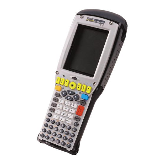
Chapter 1: Introduction The 7535 Hand-Held Computer 1.4.1 The 7535 Hand-Held Computer Figure 1.1 7535 With 58-Key Keyboard Psion Teklogix 7535/7530 Hand-Held Computer User Manual... - Page 35 Chapter 1: Introduction The 7535 Hand-Held Computer Figure 1.2 7535 Docking Port Laser Figure 1.3 Tether Port Aperture Figure 1.4 Scanner Window Psion Teklogix 7535/7530 Hand-Held Computer User Manual...
-
Page 36: Regulatory Labels
Chapter 1: Introduction Regulatory Labels 1.4.2 Regulatory Labels This label is affixed below the scanner window. Figure 1.5 Laser Warning Label This label is affixed below the scanner window. Figure 1.6 LED Radiation Warning Label Psion Teklogix 7535/7530 Hand-Held Computer User Manual... - Page 37 Chapter 1: Introduction Regulatory Labels Figure 1.7 Radio Labels Figure 1.8 Manufacturer’s Label Warning: Using controls or adjustments or performing procedures other than those specified herein may result in hazardous radiation exposure. Psion Teklogix 7535/7530 Hand-Held Computer User Manual...
-
Page 38: About The 7530 Hand-Held Computer
It supports wide area mobile applications and is built using industry standards-based software and hardware components, making it easy to integrate existing or future site infrastructures. 1.5.1 The 7530 Hand-Held Computer Figure 1.9 7530 With 37-Key Keyboard Psion Teklogix 7535/7530 Hand-Held Computer User Manual... -
Page 39: Regulatory Labels
Regulatory Labels Scanner Window Tether Port Docking Port Figure 1.10 7530 Scanner Window, Tether Port And Scanner Window 1.5.2 Regulatory Labels This label is affixed below the scanner window. Figure 1.11 Laser Warning Label Psion Teklogix 7535/7530 Hand-Held Computer User Manual... - Page 40 Chapter 1: Introduction Regulatory Labels Figure 1.12 LED Radiation Warning Label Psion Teklogix 7535/7530 Hand-Held Computer User Manual...
- Page 41 2.1.3.2 Attaching The Pistol Grip ....19 2.2 Powering Up The 7535/7530......20 2.2.1 Installing The Battery And Switching The Hand-Held On .
-
Page 43: Chapter 2: Basic Checkout
Preparing The 7535/7530 For Operation 2.1 Preparing The 7535/7530 For Operation Typically, 7535/7530 hand-helds are configured at the factory and arrive ready for use. Although these hand-helds are equipped with an internal Compact Flash and SD I/O slot, these slots are not intended for user modification. If a device needs to be changed or added in these slots, contact qualified Psion Teklogix personnel. -
Page 44: Attaching Carrying Accessories
Psion Teklogix recommends that a carrying accessory – a hand strap, pistol grip or shoulder strap – be installed on the 7535/7530 before use. If your hand-held is not fitted with a hand strap or pistol grip, you can install either using the carrying accessory kit supplied. -
Page 45: Attaching The Pistol Grip
Attaching The Pistol Grip Note: A Phillips head screwdriver is required. The pistol grip is attached to the back of the 7535/7530 using the four threaded inserts in the upper part of the 7535/7530 casing. Four black #4-40 Phillips head screws are provided with this accessory. -
Page 46: Powering Up The 7535/7530
Note: Psion Teklogix offers a Portable Docking Module (PDM) along with its power supply to help speed the checkout and confirmation process for your 7535/7530. The PDM can power your hand-held with or without a battery installed in the unit. Refer to Chapter 7: Peripheral Devices &... -
Page 47: Installing The Battery And Switching The Hand-Held On
Press and hold down the <ENTER/ON> key for at least one second. • When all four LEDs flash yellow, release the <ENTER/ON> button. A splash screen displaying the Psion Teklogix logo and the Windows CE .NET logo appears. When Windows CE has successfully loaded, the startup desktop is displayed. -
Page 48: Configuring An Ieee 802.11 Radio In The Unit
(including access keys). Important: If the 7535/7530 is equipped with a radio that has never been con- figured, the radio settings dialog box opens automatically when the unit is powered on. In this case, skip to Step 4 on page 24. - Page 49 This tab lists your radio statistics. Choosing the Zero button resets the statistics of the last four items – Packets IN, Packets OUT, IN errors and OUT errors. • Display the next tab in this window – Wireless Information. Psion Teklogix 7535/7530 Hand-Held Computer User Manual...
- Page 50 Configure button to display the Wireless Properties dialog box. Connect button – To force connection to a specific, existing network, highlight the network to which you want your 7535/7530 to connect, and choose the Connect button. Figure 2.8 Wireless Information Tab This tab lists available networks –...
- Page 51 – leave the checkbox next to This is an ad hoc network blank. If you are using an Ad Hoc network – a network in which 7535/7530s pass data directly to other 7535/7530s without an access point – highlight This is an ad hoc network, and add a checkmark in the checkbox to enable Ad Hoc.
- Page 52 Network Key & Key Index fields Figure 2.10 Accessing Network Key And Key Index Key Index: This field is used to identify the WEP key. • Enter a value from 1 to 4. Psion Teklogix 7535/7530 Hand-Held Computer User Manual...
- Page 53 The radio will search for the SSID and will compare the WEP and authentication information you specified. If there is a match between your hand- held settings and the access point settings, the hand-held will communicate on the network through the access point. Psion Teklogix 7535/7530 Hand-Held Computer User Manual...
-
Page 54: Assigning An Ip Address
In the $NETWLAN1 Settings window, display the IP Information tab. Figure 2.11 IP Information Note: Choosing the Renew button forces the 7535/7530 to renew or find a new IP address. This is useful if, for example, you are out of communication range for a longer period of time and your 7535/7530 is dropped from the network. -
Page 55: Name Servers Tab
Display the Name Servers tab. Figure 2.13 Name Servers Tab The DNS and WINS fields in the Name Servers tab allow you to specify additional WINS and DNS resolvers. The format for these fields is ###.###.###.###. Psion Teklogix 7535/7530 Hand-Held Computer User Manual... -
Page 56: Advanced Features
2.3.3.1 Rearranging Preferred Networks The 7535/7530 attempts to connect with the networks listed in this dialog box in sequence, beginning at the top of the list. If you need to rearrange this list of networks – move networks up and down in the list: •... -
Page 57: Checking The Scanner
7535/7530 via USB. For information about the USB application, refer to Appendix D: USB Setup Application. By connecting the 7535/7530 to a PC with a cable and running ActiveSync on the PC, you can: •... -
Page 58: Calibrating The Touchscreen
7535 hand-helds can be ordered with or without a touchscreens. If your 7535/7530 is equipped with a touchscreen, it will need to be calibrated. Refer to “Calibrating The Touchscreen” on page 46 for details. 2.7 Resetting The Hand-Held... - Page 59 ETTING 3.1 Features Of The 7535 ......35 3.2 Features Of The 7530 ......36 3.3 The Battery .
-
Page 60: Chapter 3: Getting To Know Your 7535/7530
3.13.1 Caring For The Touchscreen..... 63 3.13.2 Cleaning The 7535/7530..... . . 64... -
Page 61: Features Of The 7535
Chapter 3: Getting To Know Your 7535/7530 Features Of The 7535 3.1 Features Of The 7535 7535 Screen Sound Port Ambient Light Sensor Tether Port Docking Port Figure 3.1 Front Of 7535 Scanner Window Warning Label Stylus (Pointing Tool) Battery Pack Tether Port Figure 3.2 Back Of 7535... -
Page 62: Features Of The 7530
Chapter 3: Getting To Know Your 7535/7530 Features Of The 7530 3.2 Features Of The 7530 Stylus (Pointing Tool) Sound Port 7530 Screen Ambient Light Sensor Microphone Beeper Port Figure 3.3 Front Of 7530 Psion Teklogix 7535/7530 Hand-Held Computer User Manual... -
Page 63: The Battery
Figure 3.4 Back Of 7530 3.3 The Battery The hand-held operates with a Lithium-Ion battery pack. Preparing the unit for operation requires that a battery pack be charged and installed in the 7535/7530. 3.3.1 Battery Safety Important: Before attempting to install, use or charge the battery pack, it is critical that you review and follow the important safety guidelines in the section entitled “Lithium-Ion Battery Safety Precautions”... -
Page 64: Battery Chargers
Chapter 3: Getting To Know Your 7535/7530 Battery Chargers Removing The Battery Pack • If your unit is equipped with a hand strap, unhook it from the base of the battery. • Press down the release tab at the top of the battery, and slide the battery out. -
Page 65: Switching The Hand-Held On And Off
Ethernet connection. • Powered Cradle (7535 Model # HU1010, 7530 Model # CV1010) – can charge the hand-held with the battery installed in the hand-held. It can take from 1.5 to 4 hours to charge a battery. The unit’s intelligent charging system protects the battery from over-charging by terminating the charge process when the battery is at maximum capacity. -
Page 66: The Keyboard
‘on’. 3.5 The Keyboard The 7535 offers two types of keyboard layouts – a 58-key keyboard and a 36-key, large button keyboard. The 7530 also offers two types of keyboard layouts – a 63-key and a 37-key keyboard. Most of the keys on these keyboards operate much like a desktop computer. -
Page 67: The Keys
Chapter 3: Getting To Know Your 7535/7530 Activating Modifier Keys The <SHIFT>, <CTRL> and <ALT> keys operate much like a desktop keyboard except that they are not chorded (two keys held down simultaneously). The modifier key must be pressed first followed by the key whose function you want modified. -
Page 68: Alphanumeric Keyboards - 58-Key And 63-Key
In addition to alphanumeric keys that are directly accessible on the keyboard (no key combination is required) and the keys described in this chapter, the 58-key keyboard (7535) and the 63-key keyboard (7530) also provides function keys and macro keys. -
Page 69: Numeric Keyboards - 36-Key And 37-Key
Chapter 3: Getting To Know Your 7535/7530 Numeric Keyboards - 36-Key And 37-Key 3.5.4 Numeric Keyboards - 36-Key And 37-Key On 36-key 7535s and 37-key 7530s, all alpha characters are printed on the unit plastic in orange typeface above the numeric keys. To access an alpha character, you must first press the <ORANGE>... - Page 70 ‘Accept’ key between alpha selections. The ‘Accept’ key is presented as an arrow ⇒ symbol above the ‘0’ (zero) key. Pressing this key signals the 7535/7530 to display the alpha character you’ve chosen and await the next selection from the same key.
-
Page 71: The Keypad Backlight
Chapter 3: Getting To Know Your 7535/7530 The Keypad Backlight Suppose you want to type the letters ‘a’, ‘d’ and ‘g’. These alpha characters are accessed from the numeric keys <2>, <3> and <4>. • With the <ORANGE> key locked ‘on’, press <2> to type the letter ‘a’. -
Page 72: Calibrating The Touchscreen
3.6.3 Calibrating The Touchscreen If your 7535/7530 touchscreen has never been calibrated, or if you find that the stylus pointer is not accurate when you tap on an item, use the Stylus Properties dialog box in the Control Panel to recalibrate the screen. -
Page 73: 7535/7530 Indicators
Chapter 3: Getting To Know Your 7535/7530 7535/7530 Indicators • Select the Calibration tab, and then choose the Recalibrate button. Figure 3.7 Calibration Screen • Follow the directions on the calibration screen to calibrate the screen. 3.7 7535/7530 Indicators 7535s and 7530s use LEDs (Light Emitting Diode), onscreen messages and audio tones as indicators. -
Page 74: Charge Led
Radio Traffic LED Scanner LED Charge LED Figure 3.8 Keyboard LEDs Note: The LED function is identical between 7535 and 7530 hand-helds. 3.7.1.1 Charge LED The lower-right LED is reserved for internal charger/power status. This indicator is active even when the hand-held is inserted in a docking station (and in suspend mode) so that the charge status of the battery can be detected easily. -
Page 75: Radio Traffic Led
User Application LED This indicator is available for user-loaded custom Windows CE .NET applications. Refer to the 7535/7530 SDK Manual for details about this LED. Neither Windows CE .NET nor Tekterm use this LED. Psion Teklogix 7535/7530 Hand-Held Computer User Manual... -
Page 76: Onscreen Indicators
Figure 3.9 Taskbar The taskbar changes dynamically, and only those icons that are applicable are displayed. For example, if a radio is not installed in your 7535/7530, the radio signal icon is not displayed in the taskbar. Windows® Start Button If you have a touchscreen, you can display the Start Menu by tapping on the Windows®... - Page 77 When the battery power is completely depleted, a final warning window indicates that the 7535/7530 will be powered down. If the 7535/7530 is using external AC power, an AC icon is displayed in the taskbar. Full Empty...
- Page 78 Chapter 3: Getting To Know Your 7535/7530 Onscreen Indicators Narrow Band Radio Signal Quality Increasing radio signal quality is represented by vertical bars within this icon. Good Weak No Radio Reception Reception Link Tethered Devices When a peripheral is attached to the tether port and activated, an associated icon appears in the taskbar.
-
Page 79: Audio Indicators
For detailed scanner specifications and decode zone tables, refer to “Internal Scanner Specifications” beginning on page 353. The 7535 and 7530 support a wide range of scanner options to address a variety of user application requirements. The scanner installed in your unit can be configured using the Scanner Properties dialog box in the Control Panel. - Page 80 Chapter 3: Getting To Know Your 7535/7530 Internal Scanners However, external decoded scanners must be configured by scanning special configura- tion bar codes. In these cases, the scanner manufacturer provides programming manuals for configuration purposes. • For Symbol decoded scanners, refer to the appropriate programming guide: •...
-
Page 81: Scanning Techniques
Chapter 3: Getting To Know Your 7535/7530 Scanning Techniques It is critical that you review the warnings listed in the “Approvals and Safety” section at the beginning of this manual before using any of the scanners described in this chapter. “Scanning Techniques” outlines the mechanics of a successful scan. In addition, review “Scan LED Indicators”... -
Page 82: Troubleshooting
Chapter 3: Getting To Know Your 7535/7530 Troubleshooting 3.8.3 Troubleshooting If the scanner is not working, investigate the following: • Is the unit on? • Check that the bar code symbology being scanned is enabled for the hand-held you are using. Check any other parameters that affect the scan- ning procedure or the bar code. -
Page 83: Operating Internal Pdf Laser Scanners
Chapter 3: Getting To Know Your 7535/7530 Operating Internal PDF Laser Scanners 3.8.5 Operating Internal PDF Laser Scanners This scanner decodes PDF417 two-dimensional bar codes. • Turn the hand-held on. Wait until the unit has booted up completely. • Aim at the bar code and press the scan key or the trigger. The beam expands into a rectangle covering the bar code to properly scan it. -
Page 84: Operating Rfid/Scanner Modules
Turn the hand-held on. Wait until the unit has booted up completely. • Position the scanner window of the 7535/7530 no more than 1 centimetre from the tag. Depending on the type of tag you are reading, you may actu- ally need the 7535/7530 scanner window to touch the RFID tag. -
Page 85: Connecting & Disconnecting Tethered Peripherals
Chapter 3: Getting To Know Your 7535/7530 Connecting & Disconnecting Tethered Peripherals Scanning A Bar Code • Turn the hand-held on. Wait until the unit has booted up completely. • Aim at the bar code and press the scan key or the trigger. The beam expands, covering the bar code to properly scan it. -
Page 86: Monitoring The Battery And Maximizing Run Time
Keep in mind however that heavy usage or operating the 7535/7530 at temperature extremes will shorten the battery life. Lithium-Ion batteries do not require conditioning cycles and the 7535/7530 battery system (including chargers) requires no user interaction to maintain peak performance. - Page 87 Chapter 3: Getting To Know Your 7535/7530 Monitoring The Battery And Maximizing Run Time • The display backlight is the largest drain on the battery. Try to keep its brightness as low as possible. • The hand-held is ‘event’ driven – that is, when the unit is not in use, it reverts to sleep mode (even when it appears to be running), saving battery power.
-
Page 88: Storing Batteries
Chapter 3: Getting To Know Your 7535/7530 Storing Batteries 3.10.1 Storing Batteries Long term battery storage is not recommended. If storage is necessary: • Always try to use a ‘first-in first-out’ approach to minimize storage time. • Lithium-Ion batteries age much faster at elevated temperatures. Store bat- teries at temperatures between 0°... -
Page 89: Uploading Data In A Docking Station
Ethernet network. They are typically used to upload transaction data to a server computer when a radio link is not available. When a 7535/7530 is properly inserted in a docking station, a dock icon is displayed in the taskbar at the bottom of the unit screen. -
Page 90: Cleaning The 7535/7530
• Avoid abrasive cleaners, solvents or strong chemicals for cleaning. The 7535/7530 has a plastic case that is susceptible to harsh chemicals. The plastic is partially soluble in oils, mineral spirits and gasoline. The plastic slowly decomposes in strong alkaline solutions. - Page 91 4.5 Using A Dialog Box ......82 Psion Teklogix 7535/7530 Hand-Held Computer User Manual...
-
Page 93: Chapter 4: Working With Windows Ce
4.1.2 Navigating Using The Keyboard While all 7530s are equipped with touchscreens, 7535s can be ordered with or without touchscreens. If your 7535 has a standard screen (rather than a touchscreen), choosing icons and navigating dialog boxes, displaying the desktop, and so on requires keyboard input. -
Page 94: Working With Files, Folders And Programs
Go to Start Menu <BLUE><0> Table 4.1 Keyboard Navigation Keep in mind that unlike a desktop computer, the 7535/7530 does not support key chording (pressing two keys at the same time). You must press one key followed by the next in sequence. -
Page 95: The Startup Desktop
Use the arrow keys to highlight the icon you want to open or launch. • Press <ENTER>. 4.3 The Startup Desktop When the 7535/7530 boots up, the startup desktop (shell) is displayed. Any applications stored in the Startup folder start up immediately. Note: The startup folder is located in \Windows\StartUp and \Flash Disk\StartUp. -
Page 96: The Desktop Icons
PC desktop that is running Windows. My Computer Choosing this icon displays the contents of your 7535/7530 computer. If you’re not sure how to work with the files, folders and programs displayed, refer to “Working With Files, Folders And Programs” on page 68. -
Page 97: Using The Taskbar
Chapter 4: Working With Windows CE Using The Taskbar The 7535/7530 is equipped with a taskbar at the bottom of the screen. It displays icons through which you can view the battery capacity and radio signal quality of your unit. If the hand-held is attached to a charger, cradle, docking station or PDM, an associated icon is displayed. -
Page 98: The Start Menu
A check mark indicates active items. 4.4 The Start Menu Note: Some of the Start Menu items may be disabled based on the 7535/7530’s current security settings. The Start Menu lists the operations you can access and work with. It is available from the startup desktop or from within any application. -
Page 99: The Desktop
Type the underlined alpha character – for example, to display the Power Info dialog box, type the letter p. 4.4.1 The Desktop Choosing the Desktop option from the Start Menu displays the 7535/7530 desktop. Psion Teklogix 7535/7530 Hand-Held Computer User Manual... -
Page 100: Security Settings
Security Settings 4.4.2 Security Settings Choosing the Security option from the Start Menu displays a dialog box in which you can define the access level for the 7535/7530 – Supervisor or User. Figure 4.6 Security Levels Assigning The Supervisor Security Level The security level is represented by an icon in the shape of a lock in the taskbar. - Page 101 The Teklogix level security is now available in the Security Level dialog box. • Select the radio button next to Teklogix. To activate this security level, you’ll need to enter the appropriate Psion Teklogix level password in the Password field. Psion Teklogix 7535/7530 Hand-Held Computer User Manual...
- Page 102 Figure 4.9 Configuring Security This dialog box allows you to determine which security levels will have an associated icon displayed in the taskbar. By default, a security icon is not displayed for user-level security. Psion Teklogix 7535/7530 Hand-Held Computer User Manual...
-
Page 103: Programs
DOS commands such as dir to display all the directories in the drive. Internet Explorer The 7535/7530 is equipped with Microsoft Internet Explorer consistent with all Windows CE .NET devices on the market. You can access the Internet Options icon through the Start Menu under Settings, Control Panel or by double-tapping on the desktop icon My Computer and then, double-tapping on the Control Panel icon. -
Page 104: Shortcuts
Chapter 4: Working With Windows CE Shortcuts Windows Explorer The Windows Explorer installed on your 7535/7530 is consistent with all Windows CE .NET 4.2 devices. You can access this option from the Start Menu under Programs, Windows Explorer. Remote Desktop Connection Remote Desktop Connection is a 7535/7530 application used to connect to a Windows Terminal Server so that you can run a “session”... - Page 105 The Task Manager allows you to switch to another task or to end an active task. To display the task manager window: • Tap on Shortcut, Task Manager, or Press <ALT> <ESC>. Figure 4.12 Task Manager Psion Teklogix 7535/7530 Hand-Held Computer User Manual...
-
Page 106: Settings
Control Panel The Control Panel contains applets used to configure hardware, the operating system and the shell. If your 7535/7530 is running with the Psion Teklogix Tekterm application or another application, additional configuration applets may appear in the Control Panel. -
Page 107: Run
Figure 4.14 Run Dialog Box 4.4.7 Shutdown The Shutdown menu includes the following options: Suspend, Warm Reset and Cold Reset. Figure 4.15 Shutdown Sub-Menu Psion Teklogix 7535/7530 Hand-Held Computer User Manual... -
Page 108: Using A Dialog Box
Using A Dialog Box Note: This menu varies slightly depending on the security level chosen. When the 7535/7530 is set to User level, the Shutdown option is replaced by Suspend. A sub-menu is not available. At Teklogix security level, an additional option is available in the sub-menu –... - Page 109 Checkbox: This box allows you to select or deselect an option. To select or deselect a checkbox, press the <TAB> key to highlight the checkbox, and press the <SPACE> key to select or deselect it. Psion Teklogix 7535/7530 Hand-Held Computer User Manual...
- Page 110 Saving Your Choices: Once you’ve made all your changes, press the <ENTER> key to save your changes and exit the window. Note: A dialog box item that is displayed in grey text indicates that it is not currently available. Psion Teklogix 7535/7530 Hand-Held Computer User Manual...
- Page 111 5.6.3 Outgoing Tab ......121 5.6.4 Active Conn. Tab ......122 Psion Teklogix 7535/7530 Hand-Held Computer User Manual...
-
Page 112: Chapter 5: Configuration
5.10.3.8 UPC E ......170 5.10.3.9 UPC/EAN Shared Settings ....171 Psion Teklogix 7535/7530 Hand-Held Computer User Manual... - Page 113 5.10.5.14 2D DataMatrix ..... .186 5.10.5.15 2D Maxicode ..... . .186 Psion Teklogix 7535/7530 Hand-Held Computer User Manual...
- Page 114 5.12.5.4 Driver Mode Configuration ....214 5.12.5.5 Modem Information....215 Psion Teklogix 7535/7530 Hand-Held Computer User Manual...
-
Page 115: Remote Desktop Connection
Note: If you are uncertain how to move around a dialog box and make selec- tions, review “Using A Dialog Box” on page 82. When the 7535/7530 boots up, the startup desktop (shell) is displayed, and any applications stored in the Startup folder start up immediately. -
Page 116: Control Panel Icons
Control Panel. • Press the <ENTER> key. The Control Panel folder contains icons used in the setup of your 7535/7530. Figure 5.1 Control Panel 5.4 Control Panel Icons The Control Panel provides a group of icons that allow you to customize and adjust settings on your 7535/7530. - Page 117 This dialog box also allows you to activate card slots. (Refer to “Power Saving Schemes” on page 110 for details.) Psion Teklogix 7535/7530 Hand-Held Computer User Manual...
- Page 118 The client checks that the cer- tificate has been digitally signed by a certification authority that the client explicitly trusts. “Certificate Assignment” on page 115 directs you to the appropriate setup information. Psion Teklogix 7535/7530 Hand-Held Computer User Manual...
- Page 119 7535/7530 scanner will successfully read. Network And Dial-up Connections Displays a network window from which the 7535/7530 802.11 radio can be configured and an existing configuration can be executed. Refer to “Config- uring An IEEE 802.11 Radio In The Unit” on page 22 for details.
-
Page 120: Basic Setup
This icon is displayed only if a Narrow Band radio is installed in the 7530. It provides access to the Narrow Band setup screens. 5.5 Basic Setup 5.5.1 Display Properties • In the Control Panel, choose the Display icon. Figure 5.2 Choosing The Display Icon Psion Teklogix 7535/7530 Hand-Held Computer User Manual... -
Page 121: Display Contrast
The backlight is activated for a configurable amount of time if the ambient light is below a specified threshold and if the 7535/7530 is in use (key press, scanner trigger or data received from the host). The Display Properties dialog box in the Control Panel allows you to specify the intensity of the backlight along with how the backlight behaves in low-light conditions and when the unit is not in use. - Page 122 Note: Backlight changes take affect immediately. You do not need to reset the unit. ON Threshold The 7535/7530 is equipped with an ambient light sensor. This sliding bar allows you to determine how dark the ambient light needs to be before the backlight turns on. Intensity This parameter is used to adjust the light intensity of the 7535/7530 backlight.
-
Page 123: Display Appearance
ON, the backlight remains ON at the configured intensity when the 7535/7530 is operating with external power (not battery power). If the 7535/7530 is drawing power from its battery, this option is ignored and the other parameters defined in Display Properties dialog box take affect. -
Page 124: Keyboard Properties
In the Control Panel, choose the Keyboard icon. Figure 5.6 Choosing The Keyboard Icon 5.5.2.1 Key Repeat • In the Keyboard Properties dialog box, open the Repeat tab. Figure 5.7 Key Repeat Properties Psion Teklogix 7535/7530 Hand-Held Computer User Manual... -
Page 125: Keyboard Backlight
In the Keyboard Properties dialog box, open the Backlight tab. Figure 5.8 Keyboard Backlight Properties ON Threshold The ON Threshold sliding bar allows you to determine how dark the ambient light needs to be before the keyboard backlight turns on. Psion Teklogix 7535/7530 Hand-Held Computer User Manual... -
Page 126: Keyboard One Shot Modes
Chapter 5: Configuration Keyboard One Shot Modes Intensity This parameter is used to adjust the light intensity of the 7535/7530 keyboard backlight. Sliding the bar to the left darkens the keyboard backlight intensity, and sliding it to the right lightens the intensity. -
Page 127: Keyboard Macro Keys
Recording And Saving A Macro You can program up to 12 macro keys on a 58-key 7535 and a 63-key 7530. On a 36-key 7535 and a 37-key 7530, you can program a maximum of 6 macro keys. - Page 128 Executing A Macro To execute a macro: • Press the macro key to which you’ve assigned the macro. For example, if you created a macro for macro key 1, press <M1> to execute the macro. Psion Teklogix 7535/7530 Hand-Held Computer User Manual...
-
Page 129: Unicode Mapping
All user-defined Unicode mappings are listed in the Unicode Mapping tab in order of virtual key value, and then by order of the shift state. If a Unicode mapping is not listed, the Unicode mapping is mapped to the default Unicode value. Psion Teklogix 7535/7530 Hand-Held Computer User Manual... - Page 130 Pressed’. Press <SPACE> to select the shift state you want to assign. Removing Unicode Values • In the Unicode Mapping tab, highlight the item you want to delete, and choose the Remove button. Psion Teklogix 7535/7530 Hand-Held Computer User Manual...
-
Page 131: Scancode Remapping
If the scancode is remapped to a virtual key, that virtual key is displayed in the next column labelled ‘V-Key’. A virtual key that is ‘Shifted’ or ‘Unshifted’ is displayed in the third column labelled ‘Function’. Psion Teklogix 7535/7530 Hand-Held Computer User Manual... - Page 132 Virtual Key, Function And Macro The radio buttons along the side of the dialog box allow you to define to what the scan code will be remapped: Virtual Key, Function or Macro. Psion Teklogix 7535/7530 Hand-Held Computer User Manual...
- Page 133 Tap on OK to save your changes. Removing A Remap To delete a remap: • In the Scancode Remapping tab, highlight the scancode you want to delete, and tap on the Remove button. • Tap on OK. Psion Teklogix 7535/7530 Hand-Held Computer User Manual...
-
Page 134: Volume And Sound Properties
Figure 5.16 Choosing The Volume Icon 5.5.3.1 Volume Adjustments Figure 5.17 Volume Settings • Slide the volume button to the left to lower the beeper volume or to the right to increase the beeper volume. Psion Teklogix 7535/7530 Hand-Held Computer User Manual... -
Page 135: Power Management Properties
Chapter 5: Configuration Sound • Under the heading Enable sounds for, enable the conditions under which you want the 7535/7530 to emit a beep. 5.5.3.2 Sound Figure 5.18 Sound Settings The 7530 hand-held computer is equipped with a sound port. This dialog box allows you to determine the sound file that will be emitted from this port. -
Page 136: Battery Capacity
In the Power Properties dialog box, open the Schemes tab. Figure 5.21 Power Scheme Properties – AC Power And Battery Power Power Scheme This dropdown menu allows you to specify whether the unit is using AC Power or Battery Power. Psion Teklogix 7535/7530 Hand-Held Computer User Manual... -
Page 137: Suspend Threshold
‘on’ (see “Display Backlight” on page 95). When the 7535/7530 is idle – not receiving any user input (a key touch, a scan, and so on) or system activity (serial data, an activity initiated by an application, and so on), the hand-held uses the value assigned in the Switch State To Suspend field to determine when the unit will go to sleep (appear to be off). -
Page 138: Charger
This tab enables or disables power to individual CF, PC Card and SDIO slots in the unit. Figure 5.24 Card Slot Activation Remember to tap on the Apply button and then tap on OK to save your changes. Psion Teklogix 7535/7530 Hand-Held Computer User Manual... -
Page 139: Stylus Properties
Figure 5.25 Stylus Icon 5.5.5.1 Setting Double-Tap Sensitivity • In the Double-Tap tab, follow the directions to tailor the sensitivity of the stylus when you tap on the touchscreen. Figure 5.26 Setting Stylus Sensitivity Psion Teklogix 7535/7530 Hand-Held Computer User Manual... -
Page 140: Touchscreen Calibration
Follow the directions in the Calibration tab to recalibrate the screen. 5.5.5.3 Touchscreen Options This tab allows you to disable the touchscreen. • Choose the Options tab, and select the checkbox next to Disable the touch panel. Psion Teklogix 7535/7530 Hand-Held Computer User Manual... -
Page 141: Certificate Assignment
For a detailed description about Certificate setup for both the server and client-side devices (7535/7530s), refer to the following website: www.microsoft.com/windows2000/techinfo/planning/walkthroughs/default.asp - "Security Services" Note: When importing certificates, the 7535/7530 only recognizes .cer files. Psion Teklogix 7535/7530 Hand-Held Computer User Manual... -
Page 142: Bluetooth Setup
, choose the Bluetooth Device Properties icon to display Control Panel the Bluetooth Control screen. Figure 5.30 Bluetooth Icon The Bluetooth Control dialog box is used to display the other Bluetooth devices with which you can communicate. Psion Teklogix 7535/7530 Hand-Held Computer User Manual... -
Page 143: The Devices Tab
Click on the Scan button to list available devices. Figure 5.32 Available Bluetooth Devices Wait for the 7535/7530 to complete its scan (approximately 20 seconds). When scanning starts, the Scan button will change to Stop – if necessary, you can tap on this button to stop the process. - Page 144 Port column of the Services list box. You can choose to use BSP or COM as the port name. BSP is the latest Microsoft Bluetooth stack standard, but older applications assume serial ports are COM. When using COM as the port name, Psion Teklogix 7535/7530 Hand-Held Computer User Manual...
- Page 145 Devices list box, indicating that this device has a PIN set. Once a PIN is entered, it is saved in the registry. To remove the PIN: • Choose Set PIN, and press <ENTER>. Psion Teklogix 7535/7530 Hand-Held Computer User Manual...
-
Page 146: The Servers Tab
The Bluetooth connection is initiated from your 7535/7530 to the remote device – therefore the 7535/7530 is called the ‘client’ and the remote is called the ‘server’. The Servers tab displays the server profiles that can be activated in your 7535/7530. -
Page 147: Outgoing Tab
Note: To add a service to the Outgoing port, an active service must first be deactivated. Then you can choose the ‘Outgoing’ option from the Activa- tion menu (highlight a service, right-click or press the <SPACE> bar to display the Activation menu). Psion Teklogix 7535/7530 Hand-Held Computer User Manual... -
Page 148: Active Conn. Tab
Then click on OK. Although the name will have changed in the Properties menu in Bluetooth Controls, the radio only reads it on boot-up. For the changes to take effect, you must reset the 7535/7530. Psion Teklogix 7535/7530 Hand-Held Computer User Manual... -
Page 149: The Properties Tab
The Properties tab displays information about your 7535/7530, and provides some port options. The Device Name field shows the device name of your 7535/7530. This name can be changed (see the Note on the previous page for details). Device Class shows the Class of Device (e.g. desktop, hand-held), which is always set to Handheld. -
Page 150: The Bluetooth Gprs Phone
1. To set up the internet parameters, choose the Network And Dial-up Connections icon from the Control Panel. Figure 5.37 Network And Dial-up Connection Icon 2. Choose the Make New Connection icon. Figure 5.38 Creating A GPRS Connection Psion Teklogix 7535/7530 Hand-Held Computer User Manual... - Page 151 5. In the dropdown menu labelled Select a modem, choose the name of the modem with which you want to connect, and then choose the Configure button to display the Device Properties dialog box. Psion Teklogix 7535/7530 Hand-Held Computer User Manual...
- Page 152 Chapter 5: Configuration The Bluetooth GPRS Phone The 7535/7530 communicates with your phone and retrieves the parameters for the Device Properties dialog box. The 7535/7530 then disconnects. Figure 5.41 Port Settings 6. Under the Call Options tab, turn off Cancel the call if not connected within, and press <ENTER>...
- Page 153 The phone number you enter is network carrier dependent. Once you’ve specified all the necessary information, choose the Finish button. 8. In the Control Panel, choose the Dialing icon. Figure 5.44 Dialing Icon Psion Teklogix 7535/7530 Hand-Held Computer User Manual...
- Page 154 Network and Dial-up Connections icon. 11. In the network connection window, the new network configuration – in this case – GPRS Network – is displayed. Choose the new icon. Figure 5.46 GPRS Network Connection Psion Teklogix 7535/7530 Hand-Held Computer User Manual...
- Page 155 Figure 5.47 Successful Connection • Select the Hide button to move this message to the background. You can now access the internet. Figure 5.48 Accessing The Internet Psion Teklogix 7535/7530 Hand-Held Computer User Manual...
-
Page 156: Total Recall
Chapter 5: Configuration Total Recall 5.7 Total Recall Total Recall is a Psion Teklogix utility developed to maintain applications and setting over cold boots. This utility is based on a backup and restore concept. • In the Control Panel, choose the Total Recall icon Figure 5.49 Total Recall Icon... - Page 157 This dialog box lists the possible storage destinations for the profile file. • To begin, type a name for the profile in the field labelled Profile Name. The image type – OS Version and Registry Type for the 7535/7530 is also listed here. • Choose this icon to expand your settings for AutoRetore Profile and Profile Location.
- Page 158 The By File option allows you to select predefined file types. • Remove the check mark next to All Files. You’ll notice the checkbox next to By File changes , indicating that additional options are available. Psion Teklogix 7535/7530 Hand-Held Computer User Manual...
- Page 159 Choose Remove Files – a dialog box is displayed listing the files that will be backed up. • Highlight the item you want to remove from the list, and tap on the Remove button. Psion Teklogix 7535/7530 Hand-Held Computer User Manual...
- Page 160 Depending on what you have selected for inclusion in your profile, you can view a list of the selected files, databases and/or registry. Figure 5.57 Viewing Selections • Choose the Next button to perform the operation. Psion Teklogix 7535/7530 Hand-Held Computer User Manual...
-
Page 161: Restoring A Profile
Choose Restore Selected Profile from the dropdown menu, and choose the Profile Name displayed in the drop down box. Note: You can also manually restore an auto restore profile located in flash or a storage device. Psion Teklogix 7535/7530 Hand-Held Computer User Manual... -
Page 162: Ipv6 Support
Figure 5.59 IPv6 Support Icon • Choose the IPv6 Support icon to display the associated dialog box. Figure 5.60 IPv6 Support Tab • Choose the checkbox next to Enable IPv6 Network Support to enable this internet protocol. Psion Teklogix 7535/7530 Hand-Held Computer User Manual... -
Page 163: Narrow Band Radio Setup - 7530 Only
“Auto Radio Address” parameter is enabled. The “CIS Data” (Card Information Structure) is manufacturer information describing the PC Card installed in the 7535/7530. “DSP x.x / FPGA 0xNN” indicates the firmware revision of the radio’s DSP (x.x) and FPGA (0xNN) where x.x and NN represent actual revision numbers. - Page 164 Number of transmitted radio link initialization messages Number of received polls Number of transmitted retries Number of poll timeouts Number of transmitted errors rssi Received Signal Strength Indicator Table 5.1 Protocol Statistics Descriptions Psion Teklogix 7535/7530 Hand-Held Computer User Manual...
- Page 165 Number of extra characters received for last received message (due to delay Rx X in host reporting back actual body size) RxMx Maximum "Rx X" value MChg Number of completed mode changes Table 5.2 Low Level Statistics Descriptions Psion Teklogix 7535/7530 Hand-Held Computer User Manual...
-
Page 166: Channel Tab
This parameter determines the operating radio channel of the 7530 The allowable range for this parameter is . The default value is Note: The Channel Number dropdown menu displays only the channels that have been enabled in the Channel Enable List. Psion Teklogix 7535/7530 Hand-Held Computer User Manual... - Page 167 Setting this parameter to “Slow” means a higher threshold – the 7530 is more tolerant of poor communication quality. When the channel quality of the hand-held radio drops below 46%, the unit monitors the channel quality for 15 timeout periods Psion Teklogix 7535/7530 Hand-Held Computer User Manual...
- Page 168 Manual Switch Table • Tap on the Set Switch Table button to display the Manual Switch Table dialog box. Figure 5.66 Manual Switch Table Psion Teklogix 7535/7530 Hand-Held Computer User Manual...
- Page 169 • Once you’ve assigned the switching order, tap on the OK button to close the dialog box. The channel list is added to the selected channel in the Manual Switch Table dialog box. Psion Teklogix 7535/7530 Hand-Held Computer User Manual...
-
Page 170: Protocol Tab
Enable Cellular Protocol The value assigned to this parameter must be identical to the value assigned to the corresponding parameter in the Psion Teklogix Network Controller, Wireless Gateway or Base Station. A warm reset of the 7530 is required before this parameter can take effect. - Page 171 7530 channel quality decreases. If the channel quality falls to below 46%, the unit begins searching for a new channel. A value from 1 to 200 can be assigned to this parameter. Psion Teklogix 7535/7530 Hand-Held Computer User Manual...
-
Page 172: Power Tab
Tap on the OK button – the dialog box is closed and the new values are saved. To discard the new values, and retain the existing values: • Tap on the X button at the top of the dialog box. 5.9.4 Power Tab Figure 5.69 Power Tab Psion Teklogix 7535/7530 Hand-Held Computer User Manual... -
Page 173: Radio Tab
“Power Off Time” is only used when the “Enable Power Saving” parameter is enabled. The allowable range for this parameter is 1 to 60. 5.9.5 Radio Tab Figure 5.70 Radio Tab Psion Teklogix 7535/7530 Hand-Held Computer User Manual... - Page 174 To discard the new value, and keep the old “Data Squelch” value: • Tap on the X button at the top of the dialog box. The old value is sent to the protocol driver. Psion Teklogix 7535/7530 Hand-Held Computer User Manual...
- Page 175 Tap on the Yes button to go ahead or No to stop the copy process. Statistics • Tap this button to display communication statistics. Refer to “Statistics Screen” beginning on page 137 for details about this screen. Advanced This button launches the “Radio Test Application”. Psion Teklogix 7535/7530 Hand-Held Computer User Manual...
-
Page 176: Scanner Properties Setup
The Teklogix Scanners icon in the Control Panel provides dialog boxes in which you can tailor bar code options and choose the bar codes your scanner will recognize. Figure 5.72 Teklogix Scanner Icon 5.10.1 Bar Codes Figure 5.73 Scanner Properties Psion Teklogix 7535/7530 Hand-Held Computer User Manual... - Page 177 For Symbol decoded scanners, refer to the appropriate programming guide: • P300, or • LS3408. • For Symbol non-decoded scanners, refer to: • LS3200 Programming Guide. • For Power Scan (PSC) decoded and non-decoded scanners, refer to: • Powerscan Programing Guide (PSC). Psion Teklogix 7535/7530 Hand-Held Computer User Manual...
-
Page 178: Non-Decoded Scanners
Use the <UP> and <DOWN> arrow keys to highlight a parameter. • To change a parameter value, press <SPACE> or the <RIGHT> arrow key. If a field requires text entry, a text box is displayed in which you can enter the appropriate value. Psion Teklogix 7535/7530 Hand-Held Computer User Manual... -
Page 179: Non-Decoded Options
If this parameter is enabled, the characters +, %, and / are used as escape characters. The combination of an escape character and the next character is converted to an equivalent ASCII character. Psion Teklogix 7535/7530 Hand-Held Computer User Manual... - Page 180 This identifier defines the general category or specific use of the data contained in the rest of the bar code. Note: If your unit is operating with the Psion Teklogix TESS application, this parameter should not be used in conjunction with the TESS AIAG feature.
-
Page 181: Code 128
Note: The appended character is treated as any other keyboard character. For example, if <BKSP> is pressed, the usual action for that key is performed. If your unit is operating with the Psion Teklogix ANSI emulation application, the hand-held transmits the escape sequence associated with the function immediately after the bar code data. -
Page 182: Ean 13
If this parameter is enabled, the country code is included with the decoded bar code data. Include Check If this parameter is enabled, the check digit is included with the decoded bar code data. Psion Teklogix 7535/7530 Hand-Held Computer User Manual... - Page 183 Note: The appended character is treated as any other keyboard character. For example, if <BKSP> is pressed, the usual action for that key is per- formed. If your hand-held is operating with the Psion Teklogix ANSI emu- lation application, the hand-held transmits the escape sequence associated with the function immediately after the bar code data.
-
Page 184: Ean 8
If this parameter is enabled, the check digit will be included with the decoded bar code data. Addendum Important: Before “Addendum” can take effect, the “Short Code” parameter (see page 153) must be enabled. Refer to “Addendum” on page 157. Psion Teklogix 7535/7530 Hand-Held Computer User Manual... -
Page 185: Upc E
Set this parameter to on to enable “Codabar” or off to disable it. Field Size/Chars Refer to the description beginning on page 154 for details. 5.10.2.9 Code 93 Enabled Set this parameter to on to enable “Code 93”. Psion Teklogix 7535/7530 Hand-Held Computer User Manual... -
Page 186: Code 11
If this parameter is enabled, the “Mod 10” check digit is calculated. This calculation is the same as the Code 39 Mod 10 check digit. ITF Check If this parameter is enabled, the ITF-14/16 Mod10 check digit is calculated. Psion Teklogix 7535/7530 Hand-Held Computer User Manual... -
Page 187: Msi Plessey
Code 39 Mod 10 check digit. ITF Check If this parameter is enabled, the ITF-14/16 Mod10 check digit is calculated. Include Check If this parameter is enabled, the check digit is included with the decoded bar code data. Psion Teklogix 7535/7530 Hand-Held Computer User Manual... -
Page 188: Decoded (Internal) Scanners
Field Size/Chars Refer to the description beginning on page 154 for details. 5.10.3 Decoded (Internal) Scanners Figure 5.75 Decoded (Internal) Scanner • Tap on the Scanner dropdown menu, and choose Decoded (internal). Psion Teklogix 7535/7530 Hand-Held Computer User Manual... -
Page 189: Options - Decoded (Internal) Scanner
Interleaved 2 of 5). Higher security levels should be selected for decreasing levels of bar code quality. As security levels increase, the scanner’s aggressiveness decreases. Double-tapping on this parameter displays a dialog box in which you can enter a value from 1 to 4. Psion Teklogix 7535/7530 Hand-Held Computer User Manual... - Page 190 Smart Raster, Always Raster, Programmable Raster, Slab Pattern, Cyclone Pattern or Semi-Omni Pattern. 2D Raster Height And 2D Raster Expand Rate These parameter determine the laser pattern’s height and rate of expansion. Psion Teklogix 7535/7530 Hand-Held Computer User Manual...
-
Page 191: Data Options - Decoded (Internal) Scanner
Delete Char Set ECIs Setting this parameter to on enables the scanner to delete any escape sequences representing Character Set ECIs – Extended Channel Interpretations (also known as GLIs) from its buffer before transmission. Psion Teklogix 7535/7530 Hand-Held Computer User Manual... -
Page 192: Code 39
Code 32 Prefix Note: “Convert to Code 32” must be enabled in order for this parameter to function. When this parameter is enabled, the prefix character “A” is added to all “Code 32” bar codes. Psion Teklogix 7535/7530 Hand-Held Computer User Manual... - Page 193 If this parameter is enabled, the characters +, %, and / are used as escape characters. The combination of an escape character and the next character is converted to an equivalent ASCII character. Psion Teklogix 7535/7530 Hand-Held Computer User Manual...
-
Page 194: Code 128
Code 128 symbols. Increasing the performance level reduces the amount of required bar code orientation – this is useful when scanning very long and/or truncated bar codes. Keep in mind that increased levels reduce decode security. Psion Teklogix 7535/7530 Hand-Held Computer User Manual... -
Page 195: Ean 13
See “Prefix/Suffix” beginning on page 157. 5.10.3.7 UPC A Enabled Set this parameter to on to enable “UPC A”. UPC-A, Check Digit If you enable this parameter, the check digit is included with the decoded bar code data. Psion Teklogix 7535/7530 Hand-Held Computer User Manual... -
Page 196: Upc E
Conv. UPC-E To UPC-A This parameter converts UPC-E (zero suppressed) decoded data to UPC-A format before transmission. After conversion, data follows UPC-A format and is affected by UPC-A programming selections (e.g., Preamble, Check Digit). Psion Teklogix 7535/7530 Hand-Held Computer User Manual... -
Page 197: Upc/Ean Shared Settings
When you double-tap on this parameter, a dialog is displayed in which you can enter a value between 2 and 20. A value of 5 or above is recommended when Autodiscriminate is selected and you are decoding a mix of UPC/EAN symbols with and without supplementals. Psion Teklogix 7535/7530 Hand-Held Computer User Manual... -
Page 198: Codabar
Choosing Two discrete lengths allows you to decode only those codes containing two selected lengths. Length within a range allows you to decode a code type within a specified range from 5 to 55. Psion Teklogix 7535/7530 Hand-Held Computer User Manual... -
Page 199: Code 93
4 to 55. Field Size/Chars Refer to page 154 for details. 5.10.3.12 Interleaved 2 of 5 Enabled Set this parameter to on to enable “Interleaved 2 of 5”. Psion Teklogix 7535/7530 Hand-Held Computer User Manual... -
Page 200: Msi Plessey
(i.e., human readable characters), including check digit(s). Double-tapping on this parameter displays a dialog box labelled Set Code Lengths where you can define the code length that will be recognized by your scanner. Psion Teklogix 7535/7530 Hand-Held Computer User Manual... -
Page 201: Discrete 2 Of 5
(i.e., human readable characters), including check digit(s). Double-tapping on this parameter displays a dialog box labelled Set Code Lengths where you can define the code length that will be recognized by your scanner. Psion Teklogix 7535/7530 Hand-Held Computer User Manual... -
Page 202: Pdf-417
If Code 128 Emulation is set to off, the Micro PDF-417 symbols are transmitted with one of the following prefixes: if the first codeword is 903-907, 912, 914, 915 if the first codeword is 908 or 909 if the first codeword is 910 or 911 Psion Teklogix 7535/7530 Hand-Held Computer User Manual... -
Page 203: Rss Code (Reduced Space Symbology)
A composite symbol includes multi-row 2D components making it compatible with linear and area CCD scanners along with linear and rastering laser scanners. The options available for this parameter represent multi-level components of a composite symbol. Psion Teklogix 7535/7530 Hand-Held Computer User Manual... -
Page 204: Decoded (Intermec Iscp)
Tap on the Scanner dropdown menu, and choose Decoded (Intermec ISCP). 5.10.4.1 Code 39 Enable Setting this parameter to on enables “Code 39”. Field Size/Chars Refer to page 154 for details. 5.10.4.2 Code 128 Setting this parameter to on enables “Code 128”. Psion Teklogix 7535/7530 Hand-Held Computer User Manual... -
Page 205: Upc A
Set this parameter to on to enable “EAN 13”. Prefix/Suffix See “Prefix/Suffix” beginning on page 157. 5.10.4.7 UPC/EAN Shared Settings The setting assigned to the “Addendum” parameter associated with this option is shared across all UPC and EAN bar codes. Psion Teklogix 7535/7530 Hand-Held Computer User Manual... -
Page 206: Interleaved 2 Of 5
Set this parameter to on to enable “Code 11”. Field Size/Chars Refer to page 154 for details. 5.10.4.11 Codabar Enabled Set this parameter to on to enable “Codabar”. Field Size/Char Refer to page 154 for details. Psion Teklogix 7535/7530 Hand-Held Computer User Manual... -
Page 207: Imager
Enabled Set this parameter to on to enable “MSI Plessey”. Field Size/Char Refer to page 154 for details. 5.10.5 Imager Figure 5.78 Imager • Tap on the Scanner dropdown menu, and choose Imager. Psion Teklogix 7535/7530 Hand-Held Computer User Manual... -
Page 208: Options - Imager
Setting this parameter to on speeds the “Auto Exposure” process. It allows the imager to rapidly snap a number of bar code capture attempts while finding ideal values for gain, integration and illumination. Psion Teklogix 7535/7530 Hand-Held Computer User Manual... -
Page 209: Code 39
This parameter allows you to enable the following UPC (Universal Product Code) and EAN (European Article Numbering) bar codes: UPC-A, UPC-E, UPC-E1, UPC-8, EAN-13, Bookland EAN-13 and Bookland EAN. Enabled Set this parameter to on to enable “UPC/EAN” bar codes. Psion Teklogix 7535/7530 Hand-Held Computer User Manual... -
Page 210: Codabar
Set this parameter to on to enable “Interleaved 2 of 5”. Field Size/Chars Refer to page 154 for details. 5.10.5.8 Postal: Australian Enabled Set this parameter to on to enable “Postal: Australian”. Field Size/Chars Refer to page 154 for details. Psion Teklogix 7535/7530 Hand-Held Computer User Manual... -
Page 211: Postal: Japanese
Set this parameter to on to enable “Postal: PostNET”. Field Size/Chars Refer to page 154 for details. 5.10.5.13 Postal: Royal Enabled Set this parameter to on to enable “Postal: Royal”. Field Size/Chars Refer to page 154 for details. Psion Teklogix 7535/7530 Hand-Held Computer User Manual... -
Page 212: Datamatrix
Set this parameter to on to enable “2D Micro PDF-417”. Field Size/Chars Refer to page 154 for details. 5.10.5.18 2D QR Code Enabled Set this parameter to on to enable “2D QR Code”. Field Size/Chars Refer to page 154 for details. Psion Teklogix 7535/7530 Hand-Held Computer User Manual... -
Page 213: Rss Code
Set this parameter to on to enable “Composite” bar code scanner. Important: To successfully read this type of bar code, the two types of symbologies included in the composite must be enabled. In addition, “Center Bar Code Only” must be disabled. Psion Teklogix 7535/7530 Hand-Held Computer User Manual... -
Page 214: Decoded (External)
Figure 5.79 Tether And Console Port Settings While you cannot configure the scanner, you can configure communications with a serial decoded scanner using the options in this tab. 5.10.6.1 Tether Port Figure 5.80 Tether Port Settings Psion Teklogix 7535/7530 Hand-Held Computer User Manual... - Page 215 Double-tapping on this option displays a pop-up window in which you can choose the appropriate Parity. Figure 5.82 Parity Settings Stop Bits This parameter specifies the number of stop bits – 1, 1.5 or 2 – used for asynchro- nous communication. Psion Teklogix 7535/7530 Hand-Held Computer User Manual...
-
Page 216: Console Port
Console Port 5.10.6.2 Console Port Figure 5.83 Console Port Settings Enabled This parameter must be set to on in order for the 7535/7530 to recognize the device connected to the console port. Baud Refer to page 189 for details. Data Bits Refer to page 189 for details about this parameter. -
Page 217: Options Tab
Click Data For both integrated and external scanners, this parameter determines which character is sent to the application installed in your 7535/7530 following a double-click. A dialog box appears, asking that you press the key you want to insert. The ASCII/Unicode key value of the keypress is displayed. - Page 218 Good Scan Beep And Bad Scan Beep These parameters determine whether or not the 7535/7530 emits an audible scanner ‘beep’ when a good (successful) scan or a bad (unsuccessful) scan is performed. Set these parameters to either on to enable the beeper or off to disable it.
-
Page 219: Translations
“Output” string. This string entry parameter can be null, or it may contain any combination of standard and special characters (e.g., function keys, <ENTER>, etc.). Psion Teklogix 7535/7530 Hand-Held Computer User Manual... -
Page 220: Snmp (Simple Network Management Protocol) Setup
All Teklogix products support the TEKLOGIX-GENERIC-MIB – a MIB that defines some common features across Teklogix products. All devices also support MIB-II, a management information base that defines the common features of TCP/IP networks. The SNMP Agent software embedded in the 7535/7530 product supports SNMPv1 (RFC 1157). •... -
Page 221: Contact Tab
MIB-II’s sysContact object. Location This parameter is used to identify the physical location of this node (e.g., Warehouse A: Pillar 32B). The content of this parameter is accessible through MIB-II’s sysLocation object. Psion Teklogix 7535/7530 Hand-Held Computer User Manual... -
Page 222: Communities Tab
Enabling Enable SNMP allows the device to respond to SNMP queries and to send Traps. After enabling this option and rebooting the device, the SNMP Agent will automatically start up. To disable this feature, remove the check mark from the check box. Psion Teklogix 7535/7530 Hand-Held Computer User Manual... -
Page 223: Adding A Community
The value assigned here is the name assigned by the network administrator to the set of devices to which this managed node belongs. Rights This menu allows you to specify access – that is, ‘Read-Only’ or Read-Write’ Psion Teklogix 7535/7530 Hand-Held Computer User Manual... -
Page 224: Modifying A Community Setting
Remove button. A Delete Confirmation screen is displayed. • To remove a community, choose the Yes button, or If you decide not to remove the community, choose the No button. Psion Teklogix 7535/7530 Hand-Held Computer User Manual... -
Page 225: Trap Destination Tab
(e.g., an SNMP message received with a bad community name). 5.11.3.2 Adding A Destination To add a new destination: • Choose the Add button. Figure 5.93 Adding A Trap Destination • Type a destination in the text box provided, and press <ENTER>. Psion Teklogix 7535/7530 Hand-Held Computer User Manual... -
Page 226: Changing A Destination
• Choose the Remove button. A Delete Confirmation screen is displayed. • To remove a destination, choose the Yes button, or If you decide not to remove the destination, choose the No button. Psion Teklogix 7535/7530 Hand-Held Computer User Manual... -
Page 227: Permitted Hosts Tab
To add a new host: • Highlight the Add button, and press <ENTER>. Figure 5.96 Adding A Host • Type a new host IP address in the text box provided, and press <ENTER>. Psion Teklogix 7535/7530 Hand-Held Computer User Manual... -
Page 228: Wireless Wan
• Make the necessary changes, and press <ENTER>. 5.12 Wireless WAN A 7535/7530 equipped with a GSM/GPRS or CDMA/1xRTT radio provides wide area networking capabilities. 5.12.1 Taskbar Icons Wireless WAN icons in the taskbar indicate the status of your wide area network connection. -
Page 229: Establishing A Connection
If the icon is not visible in the taskbar (the radio interface has been shut down or the modem has been removed): • In the Control Panel, choose the Wireless WAN icon. Figure 5.97 Wireless WAN Icon Psion Teklogix 7535/7530 Hand-Held Computer User Manual... - Page 230 PPP link to modem active • Authenticating user • User authenticated • Connected Note: Keep in mind that these states may be displayed fairly quickly if the progress of the connection is rapid. Psion Teklogix 7535/7530 Hand-Held Computer User Manual...
-
Page 231: Disconnecting From A Network
To disconnect from the network: • Tap the stylus on the Disconnect button, and then on OK. When the 7535/7530 network connection is severed, the Status field displays Ready to connect. A unit equipped with a GSM/GPRS expansion board displays the signal strength in the main Wireless WAN screen, even while a connection is active. -
Page 232: Advanced Information
Advanced Information 5.12.4 Advanced Information In most cases, when a GSM/GPRS radio and SIM are installed in your 7535/7530, setup is automatic. Follow the steps outlined under the heading “Establishing A Connection” on page 203 to make a connection. The information in this section is for advanced setup purposes. -
Page 233: Error States
• NDIS error An internal software error has occurred. If a warm boot does not clear this condition, Psion Teklogix technical support may need to investigate further. Psion Teklogix 7535/7530 Hand-Held Computer User Manual... -
Page 234: Tools Menu
Wireless WAN user interface will attempt to establish a GPRS connection whenever GPRS is available (e.g. after resume from suspend without further user interaction). To activate the automatic connection mode: • Tap on the OK button. Psion Teklogix 7535/7530 Hand-Held Computer User Manual... - Page 235 Every profile is identified by an arbitrary, unique name. The profile named Default is special in that it is always present and can neither be edited nor deleted. (A sample dialog box is presented in Figure 5.101 on page 208.) The Psion Teklogix 7535/7530 Hand-Held Computer User Manual...
- Page 236 The parameters of the selected profile can be edited when you choose the Edit button. Keep in mind that you cannot edit the Default profile. Delete The selected profile is deleted. You cannot delete the Default profile. Psion Teklogix 7535/7530 Hand-Held Computer User Manual...
- Page 237 Activation is possible only if the Enable automatic configuration: checkbox is unchecked. Reset The Reset button in the New Profile and Edit Profile dialog boxes resets all entry fields to the values they had when the dialog box was opened. Psion Teklogix 7535/7530 Hand-Held Computer User Manual...
-
Page 238: Security Configuration
PIN (such as resume after suspend or modem removal). The stored PIN is also automatically entered in the Current PIN text box whenever the Security Configuration dialog box is called up. Psion Teklogix 7535/7530 Hand-Held Computer User Manual... -
Page 239: Network Configuration
WWAN dialog box changes to ‘Emergency calls only’, ‘No net- work found’, ‘GPRS not available’ or ‘GPRS not allowed’. Psion Teklogix 7535/7530 Hand-Held Computer User Manual... -
Page 240: Driver Mode Configuration
GSM modem connected to a serial port of the computer through USB or through Bluetooth. An external modem connected to a serial port must support 115.2kbit/s, 8bit, no parity and hardware flow control. Psion Teklogix 7535/7530 Hand-Held Computer User Manual... -
Page 241: Modem Information
Figure 5.105 Modem Data The fields in this dialog box cannot be edited – they only display information about the 7535/7530 modem. If the network operator has not programmed a user’s phone number into his SIM, the Phone: field remains empty. - Page 243 6.2.1 Function Keys And Softkeys .....221 6.2.1.1 7535 Function Keys .....221 6.2.1.2 7530 Function Keys .
- Page 244 6.10.4 Retrieving Default Parameter Values ....249 6.11 Resetting The 7535/7530 Hand-Held Computer ... . . 249 6.12 The Parameters Menu .
- Page 245 6.21.2 802.IQ v2 ......318 Psion Teklogix 7535/7530 Hand-Held Computer User Manual...
-
Page 247: Chapter 6: Tekterm Application
Tekterm supports function keys, softkeys and macro keys. 6.2.1 Function Keys And Softkeys The 7535/7530 is equipped with a series of function keys each of which is defined in the application software. Depending on the type of keyboard on your hand-held –... -
Page 248: 7530 Function Keys
Press the <BLUE> key followed by the alpha key to which the function key you want to use is mapped. For example: To access function key <F11>, press <BLUE> <C>. To access function key <F12>, press <BLUE> <D>, and so on. Psion Teklogix 7535/7530 Hand-Held Computer User Manual... -
Page 249: Softkey Function Keys
<F4> SAVE – Saves a change to a parameter value. LITRL – Literal mode allows special characters to be <F5> entered in a string parameter such as macro key strings. Table 6.1 Softkeys Psion Teklogix 7535/7530 Hand-Held Computer User Manual... -
Page 250: Macro Keys
Refer to “Keyboard Macro Keys” on page 101 for details about creating macros. 7535/7530 hand-helds are equipped with a series of macro keys that can be programmed to replace frequently used keystrokes, along with the function of executable keys like the <ENTER> key, the <BKSP> key, any function key and arrow key, and so on. -
Page 251: Changing The Screen Font Size
259 for additional details. 6.4 Panning The Screen Contents If the content of a screen is too large to fit in the margins of the 7535/7530 display, the content can be panned or shifted to bring the information outside the margins into view. -
Page 252: Using The Task Manager To Switch Between Applications
To end or close an application: • Highlight the application you want to end, and tap on the End Task button. If you’re using the keyboard: • Press <TAB> to highlight the End Task button, and press <ENTER>. Psion Teklogix 7535/7530 Hand-Held Computer User Manual... -
Page 253: The Tekterm Status Area
TESS commands. The 9150 Access Point is also equipped with protocol emulation software. Note: If the message “RESET: Press Enter” flashes at the bottom of the TESS screen when you turn on the 7535/7530, press the <ENTER> key once. Psion Teklogix 7535/7530 Hand-Held Computer User Manual... -
Page 254: Configuration
Bar code only Field – is filled with data from a bar code reader. Keyboard entries are not accepted in this type of field. Serial I/O Field – is filled with data coming from a serial port. Keyboard input is not accepted in this type of field. Psion Teklogix 7535/7530 Hand-Held Computer User Manual... -
Page 255: Ibm 5250 Emulation Keys
Home (Home key) screen. 6.6.5 Data Entry The 7535/7530 accepts data until the operator presses a key that sends a transmission to the host computer. The following actions cause the 7535/7530 to transmit: • Pressing a function key or the <ENTER> key (which is considered to be <F0>) causes the hand-held to transmit. -
Page 256: Tess Edit Modes And Cursor Movement
Note: When the “Enter on Arr” parameter is disabled (set to “N”), the <UP> and <DOWN> arrow keys do not complete an entry field. Refer to page 298 for details about this parameter. Psion Teklogix 7535/7530 Hand-Held Computer User Manual... -
Page 257: Del> Key Behaviour In Tess
• If the <DEL> key is pressed while cursor is in the right most Replace mode position in the field, the 7535/7530 emits a keyboard error beep. • If the <DEL> key is used to clear data in a field that has been... -
Page 258: Bksp> Key Behaviour In Tess
Field mode • If the <BKSP> key is pressed when the field is empty, the 7535/7530 emits a keyboard error beep. • The <BKSP> key does not delete data pre-filled by the host applica- tion. -
Page 259: Tess Status Message
• Press <CTRL> <W> to make this message appear only when the 7535/7530 locks. The message should look similar to the sample below: V6.0 fld 0.6 “V6.0” is the TESS version number. “fld” indicates that TESS is currently in field mode. -
Page 260: Lock Messages
6.6.7 Lock Messages When information is transmitted to the host computer, the keyboard locks to prevent further data entry until the 7535/7530 receives a reply. A locked state is indicated by either “LOCK-B” (base) or “LOCK-H” (host) in the lower left corner of the display. -
Page 261: The Local Menu
The Local Menu 6.6.10 The Local Menu The host can store local procedures in the 7535/7530 for use when the unit is off-line. A menu of these procedures appears whenever <CTRL> <L> is pressed (see “Figure 6.3” on page 235). -
Page 262: Queuing Mode
6.7.1 Configuration To configure the 7535/7530 for ANSI mode, the “Name” and “Type” of session – in this case, ANSI – must be specified in the Applications menu. This menu is described in the section titled, “Applications” on page 267. -
Page 263: Sending Data To The Host
The 7535/7530 provides parameters that determine when the computer transmits characters to the host. The 7535/7530 can be configured to transmit after a number of characters are typed in (the “Xmit Count” parameter) or after some time has elapsed (the “Xmit Wait”... -
Page 264: Block Mode (Local Editing)
Table 6.2 Psion Teklogix Keyboard And VT220 Equivalent Keys 6.7.4 Block Mode (Local Editing) Psion Teklogix 7535/7530s support “block mode” (or Local Editing). Application programs must be specifically written to support this mode. For software that supports this mode, the keys shown in Table 6.3 "Function Of Keys In Block Mode"... -
Page 265: Working With Sessions
Press <CTRL>, and type a lowercase a. • At the TCP> prompt, type cl in lowercase letters followed by the session number you want to close. e.g., Type cl 2 to close session 2. • Press <ENTER>. Psion Teklogix 7535/7530 Hand-Held Computer User Manual... -
Page 266: The Radio Statistics Screen
In the Title field, type a name for the radio screen – e.g., Radio. • Press <F4> to save your changes, and then reset the 7535/7530 – press and hold down the <BLUE> and <ENTER> keys for a minimum of 6 seconds. - Page 267 MAC address of the hand-held computer. • bootnum e.g., C33B – the boot number of the network control- ler. This number increments each time the controller reboots so that hand-helds can detect the reboot when they reinitialize. Psion Teklogix 7535/7530 Hand-Held Computer User Manual...
- Page 268 (hex). • radio address. This is the Cellular Address, including session number (hex). • host terminal number of session (decimal). • session status (hex). • data stream type (hex). • message mask (hex). Psion Teklogix 7535/7530 Hand-Held Computer User Manual...
-
Page 269: The Tekterm Startup Display Menu
6.9 The Tekterm Startup Display Menu The values assigned to Tekterm parameters can be viewed and adjusted to optimize communication at the site in which a 7535/7530 is operating. While some parameters are accessible through the “Parameter Manager”, others can be adjusted through the Windows CE .NET Control Panel. -
Page 270: Working With Menus
Working With Menus 6.10 Working With Menus The 7535/7530 offers two ways to navigate menus and choose values – you can use the keyboard, or you can select items by tapping a stylus on the screen. (Keep in mind that some 7535s are not equipped with touchscreens — in these cases, navigation will be limited to the keyboard.) -
Page 271: Numeric Parameters
“Macro Control Panel” on page 255. A sequence or string of characters can be entered in this type of parameter. When a string entry parameter contains data, it is displayed in reverse video. (Empty fields Psion Teklogix 7535/7530 Hand-Held Computer User Manual... - Page 272 To add another ASCII character in the string entry field, next to the one you’ve already chosen: • Type a numeric character – for example, type the number 7. • Next, press the <BKSP> key. Psion Teklogix 7535/7530 Hand-Held Computer User Manual...
-
Page 273: Using The Touchscreen To Navigate Through Menus
The “»” character appearing to the right of the menu item indicates that it has a sub-menu. Displaying Sub-Menus To display a sub-menu: • Tap the stylus on the menu item with the sub-menu you want to display. Psion Teklogix 7535/7530 Hand-Held Computer User Manual... -
Page 274: Numeric Parameters
To cycle through the set: • Tap the stylus on the alpha field to cycle through the options. Psion Teklogix 7535/7530 Hand-Held Computer User Manual... -
Page 275: Saving Changes To Parameters
Reset the 7535/7530. See “Resetting The 7535/7530 Hand-Held Computer” in the next section. 6.11 Resetting The 7535/7530 Hand-Held Computer Some parameter adjustments require that the 7535/7530 be reset before the changes can take effect. To reset the 7535/7530: • Press and hold down the <BLUE> key and the <ENTER/ON> key simulta- neously until all LEDs illuminate yellow (approximately six seconds). -
Page 276: The Parameters Menu
A reset results in a complete reboot of the unit. All RAM memory contents are lost. The contents of the flash memory and memory card are preserved. When the 7535/7530 is reset, the screen displays the Psion Teklogix and Microsoft® Windows® CE .NET splash screen before displaying the startup desktop. -
Page 277: Display Options
The “More Parameters” sub-menus contain the Tekterm parameters and can only be accessed with the proper security password – either a Supervisory or a Teklogix password. (Refer to “Security Settings” on page 74 for details.). Psion Teklogix 7535/7530 Hand-Held Computer User Manual... -
Page 278: Radio Parameters
Note: A Narrow Band radio is available for 7530 hand-held. For details on set- ting up this radio, refer to “Narrow Band Radio Setup — 7530 Only” on page 137. For 7535/7530s equipped with 802.11 radios, follow the directions following. Psion Teklogix 7535/7530 Hand-Held Computer User Manual... - Page 279 Radio Address The value entered in the “Radio address” parameter is used to identify the 7535/7530 over the radio link. A unique value from 1 to 3840 must be assigned for each hand-held computer. Psion Teklogix 7535/7530 Hand-Held Computer User Manual...
-
Page 280: System Parameters
If an acknowledgement takes longer to receive than the average round trip time calculated, the computer will resend the transmission. Because 7535/7530s cannot calculate an average round trip time without a number of transmissions, a starting point or “Initial Round Trip Time” is required. The com- puter uses the time assigned to the “Initial RTT”... -
Page 281: Keyboard
6.16.1.2 Indicators When the “Indicators” parameter is enabled (set to “Y”), onscreen indicators are displayed to indicate the operating condition of the 7535/7530. Refer to “Onscreen Indicators” on page 50 for a list of possible indicators. Psion Teklogix 7535/7530 Hand-Held Computer User Manual... -
Page 282: Softkeys
<BLUE> and <ORANGE> keys. Figure 6.7 Keyboard Properties Important: Refer to “Keyboard Properties” on page 98 for details about this dialog box. Psion Teklogix 7535/7530 Hand-Held Computer User Manual... -
Page 283: Audio
Scan Reject /windows/default/wav Sounds Ctrl Panel » see text The 7535/7530 emits a beep under a variety of conditions. The “Audio” menu above lists the conditions under which your hand-held will sound. Sounds Ctrl Panel This option displays the Volume & Sounds Properties dialog box. This dialog box is used adjust the beeper volume and to select the conditions under which the 7535/7530 will emit a beep. -
Page 284: Power Mgmt Ctrl Panel
Screen Switch When set to “Y”, the operator can use the “Split screen” parameter to toggle between screens when multiple applications are running on the 7535/7530. Refer to “Split Screen” on page 261 for details about using this function. Psion Teklogix 7535/7530 Hand-Held Computer User Manual... -
Page 285: Windows Properties
6.16.6 Auto Start “Auto Start” determines whether or not Tekterm is automatically launched when the 7535/7530 is reset. If this parameter is set to “N”, Tekterm will not be launched when the hand-held resets. Psion Teklogix 7535/7530 Hand-Held Computer User Manual... -
Page 286: Scanner Control Panel
Default Colours» see text Display Shift If this parameter is enabled (set to “Y”), the display in application screens shifts so that there are no blank columns on the left-most side of the display. Psion Teklogix 7535/7530 Hand-Held Computer User Manual... -
Page 287: Split Screen
“Type” and “View IDs”, are used to tailor the screen view for your needs. Type And View IDs The “Type” parameter determines how a screen will be split. The 7535/7530 supports up to four application screens. The “View IDs” parameter determines which application screens will be displayed in each pane of the split screen. -
Page 288: Splitting And Displaying Screens
TESS session in the right pane. In the “Display Menu”, the letter A represents “Parameters” and B represents “TESS”. The “Type” and “View ID” values would be represented as follows: Split screen Type 2 Way ||| View IDs • Press <ENTER>. Psion Teklogix 7535/7530 Hand-Held Computer User Manual... -
Page 289: Moving Between Split Screens
Chapter 6: Tekterm Application Moving Between Split Screens To display the split screen on the 7535/7530: • Press <CTRL> <DOWN> arrow. 6.18.1.2 Moving Between Split Screens To move the cursor from one pane in a split screen to the next: •... -
Page 290: Custom Characters (Unicode™)
• Highlight “Custom Chars”, and press <F1> to display the custom characters table. 04 Custom Chars Font Small 0000 0000 • Position the cursor on the Fonts at the top of the table. Psion Teklogix 7535/7530 Hand-Held Computer User Manual... -
Page 291: Displaying The Unicode™ Pop-Up Window
• Press <F4> to save your changes. • Reset the 7535/7530 – press and hold down the <ENTER> and <BLUE> key simultaneously for a minimum of six seconds. 6.18.2.2 Displaying The Unicode™ Pop-up Window The Unicode™ values you create are stored in a pop-up window that you can access from any application. - Page 292 The allowable values are: Red, Green, Yellow, Blue, Magenta, Cyan, White and Black. Note: The 7535/7530 must be reset – press and hold down the <BLUE> and <ENTER> keys for a minimum of six seconds – in order for the new colour assignments to take affect.
-
Page 293: Applications
Chapter 6: Tekterm Application Applications 6.19 Applications “TESS” and “ANSI” applications require unique names so that several different sessions of “TESS” and “ANSI” can operate simultaneously. 7535/7530s can support up to 8 sessions at one time. Range Applications Type1 ANSI... -
Page 294: Ansi Settings
For every application session you create, the “Terminal #” assigned must be non-zero and unique. This parameter defines the number for the ANSI session and uniquely identifies all transmissions to and from the 7535/7530. Psion Teklogix 7535/7530 Hand-Held Computer User Manual... -
Page 295: Host Conn
Chapter 6: Tekterm Application Host Conn Other applications running in the 7535/7530, such as a TESS session or another ANSI session must each have a different number. In addition, each Psion Teklogix 7535/7530 using the radio link must have a unique number. - Page 296 The “Auto Login” parameters are used to define whether or not the hand-held will attempt to log in automatically. The Auto Login sequence is as follows: 1. Host sends “Login Prompt”. 2. Hand-held responds with “Login”. 3. Host sends “Password Prompt”. Psion Teklogix 7535/7530 Hand-Held Computer User Manual...
- Page 297 When this parameter is set to “Y”, the host will echo data back to the hand-held after receiving a “Password”. Login Failed When the hand-held unit receives this string, it assumes that the login attempt has failed and returns to the “Enter Pmpt”. Psion Teklogix 7535/7530 Hand-Held Computer User Manual...
- Page 298 The ‘Arrow Key Remap’ table allows these arrow key character sequences to be redefined. Arrow Key Remap Up Arrow Down Arrow Right Arrow 1B Left Arrow Psion Teklogix 7535/7530 Hand-Held Computer User Manual...
-
Page 299: Screen
Display panning is used if the page is longer than the display. Note: The value in this parameter must be an even number. Psion Teklogix 7535/7530 Hand-Held Computer User Manual... - Page 300 Note: The value in this parameter must be an even number. Default font This parameter determines the default font that appears when the 7535/7530 memory is reset. • Use the <RIGHT> or <LEFT> arrow key to scroll through the available options.
- Page 301 Label menu, and type a new name – preferably one that describes the corresponding key’s function. Note: Although you can enter up to 9 characters for each softkey label, the text will be shortened to better fit in the available space on your display. Psion Teklogix 7535/7530 Hand-Held Computer User Manual...
-
Page 302: Xmit Modes
Chapter 6: Tekterm Application Xmit Modes Colour Override Note: If you are using a 7535 equipped with a monochrome display, this menu is not available. Range Colour Override Foreground Black see text Background White see text Foreground And Background When “Colour Override” is set to ‘Y’, the colours chosen in this menu are displayed in the ANSI sessions. - Page 303 Auto-Answer This string can be up to 30 characters long and is sent by the 7535/7530 as a reply to an “ENQ” character from the host. The “Auto-Answer” string is programmable in the same manner as the keyboard macros.
- Page 304 Terminal Programmer’s Manual for more information. Kbd lock When this parameter is disabled (set to “N”), the 7535/7530 does not lock the keyboard after a block mode transmission. When enabled (set to “Y”), the keyboard is locked after a transmission. The application program must unlock the keyboard by resetting the Keyboard Action Mode (KAM), using the Reset Mode (RM) or Enable Manual Input (EMI) controls.
- Page 305 If the parameter is not used, the rules specified in “Transmitted Data Stream” are used to determine end of line characters. EOB chars This string entry parameter specifies a string of up to 8 characters that are sent after each block transmission. Psion Teklogix 7535/7530 Hand-Held Computer User Manual...
-
Page 306: Kbd Modes
When set to “cursor”, pressing the <LEFT> and <RIGHT> arrow keys move the cursor within the current field. Echo Mode This parameter selects echo mode for the 7535/7530. The available modes are “Local”, “Host”, and “Smart”. Local: In this mode, any character entered using the keyboard is displayed before being sent to the host. - Page 307 This parameter determines the “hot-key” for printing the screen contents via the 7535/7530 serial port. The default is <CTRL> P (16). Note: The 7535/7530 port must be set to “printer” (see“Ports — Tether And Console” on page 308). Psion Teklogix 7535/7530 Hand-Held Computer User Manual...
- Page 308 The <ENTER> key normally enters data into a field and moves the cursor to the next field. However, some applications require that the <ENTER> key start a transmission from the 7535/7530. When enabled (set to “Y”), this parameter causes the <ENTER> key to start a transmission.
-
Page 309: Edit Modes
ANSI mnemonics are displayed in reverse video. Other characters are displayed as normal characters. This mode can also be set with the Set Mode (SM) control but can only be reset from the Parameters menu. Psion Teklogix 7535/7530 Hand-Held Computer User Manual... -
Page 310: Serial
ANSI print commands (such as ‘MC’ or Media Copy) control the transfer of data to and from the serial and console ports on the hand-held. At the 7535/7530, the value assigned at the ‘Primary Port’ and ‘Secondary Port’ parameters determines which port the ANSI print command will identify and use as primary and secondary. -
Page 311: Tess Settings
Fields » see text Anchor View N» see text Emulation » see text Each session you create has its own “Settings” parameters. Additional TESS information is documented in “TESS Emulation” on page 227. Psion Teklogix 7535/7530 Hand-Held Computer User Manual... -
Page 312: Host Conn
This parameter defines the terminal number for the TESS session and uniquely identifies all transmissions to and from the 7535/7530. Other applications running in the 7535/7530, such as an ANSI session or another TESS session must each have a different number. In addition, each Psion Teklogix 7535/7530 using the radio link must have a unique number. -
Page 313: Screen
This parameter defines the logical page width (in characters) used by the host computer application. Emulator systems trim the host application screens to this width. This page width cannot be smaller than the width of the 7535/7530 display. Display panning is used if the page is wider than the display. - Page 314 This parameter determines the number of pages that can be stored and recalled at the 7535/7530. Storing frequently used page data at the 7535/7530 reduces the need for the host to retransmit complete page data over the radio link. Retransmitting data can reduce the system response time.
-
Page 315: Characters
Note: Although you can enter up to 8 characters for each softkey label, the text will be shortened to better fit in the available space on your display. Colour Override Note: If you have a 7535 with a monochrome display, this menu is not available. Range Colour Override... - Page 316 Misc. N » This menu contains all the character sets available with your Psion Teklogix computer. In this menu, the “Y” or “N” is used to visually guide you to the selected character set. For example, in the sample menu above, the “Y” next to IBM indicates that a character set has been chosen from this group.
-
Page 317: Tests
Field matching allows the host to pre-load data into an entry field that is compared with the user’s input. The 7535/7530 beeps if the entered data does not match. Hidden field matching means that the data to be matched is not displayed in the entry field. -
Page 318: Features
Binary print When this parameter is enabled (set to “Y”), the page displayed on the 7535/7530 computer is spooled as is, except for trailing white-space removal. When disabled (set to “N”), each line of the page displayed on the hand-held is preceded by a linefeed (LF) and followed by a carriage return (CR). - Page 319 The menu item “Local Process” has a sub-menu attached to it – “Save on Reset”. When this parameter is enabled (set to “Y”), data stored in the 7535/7530 is saved if the unit is reset. Local procedures are defined on page 235.
- Page 320 TESS print commands control the transfer of data to and from the serial and printer ports on the 7535/7530. At the 7535/7530 computer, the value assigned at the ‘Serial Port’ parameter ranks which port the TESS print command will identify and use as the first to fourth port.
- Page 321 SO suffix This parameter determines the end-of-message character on serial output. Enter an ASCII numeric equivalent from 0 to 255 to represent the end character. A value of “0” (zero) indicates no suffix. Psion Teklogix 7535/7530 Hand-Held Computer User Manual...
-
Page 322: Scanner
Append F0 When enabled (set to “Y”), this parameter causes an <F0> code to be appended to the bar code. The <F0> code completes the entry of the bar code data in the field. Psion Teklogix 7535/7530 Hand-Held Computer User Manual... -
Page 323: Fields
When enabled (set to “Y”), the cursor moves according to field location. If disabled (set to “N”), the cursor moves according to the numeric order of the fields. Psion Teklogix 7535/7530 Hand-Held Computer User Manual... - Page 324 The <ENTER> key normally enters data into a field and moves the cursor to the next field. However, some applications require that the <ENTER> key start a transmission from the 7535/7530. When enabled (set to “Y”), this parameter causes the <ENTER> key to be interpreted as <F0> which starts a transmission.
- Page 325 Enh Edit Mode This mode provides extended (enhanced) functions to users of Psion Teklogix’ IBM 5250 terminal emulation. When this parameter is enabled (set to “Y”), the arrow keys move the cursor anywhere on the screen, unrestricted by fixed or entry fields.
-
Page 326: Anchor View
Send CR with FKEY A function key press generates a string of text to be sent back to the host. If this parameter is enabled, a carriage return is appended to the function key. Psion Teklogix 7535/7530 Hand-Held Computer User Manual... - Page 327 Note: This operation is only performed on screens received from the host. Data sent to the host remains unaffected. Passthru Printing Setting this parameter to ‘Y’ allows the host to send data directly to the 7535/7530 serial port. This option is most commonly used for printing. AIAG Character This parameter is used to enter a decimal representation of the ASCII character code of the AIAG character.
- Page 328 The application program distinguishes this field as Serial I/O by preceding the field with a special character. If this character precedes a fixed field, the data will be sent to the 7535/7530’s serial port. If it precedes an entry field, the field accepts data from the hand-held’s serial port.
- Page 329 When the system request key is pressed, a Telnet “Interrupt Process” command is generated. The “Interrupt Process” command is sent to the host in place of the standard mechanism used to send the system request key press to a host using Telnet. Psion Teklogix 7535/7530 Hand-Held Computer User Manual...
- Page 330 Telnet. LU Name Enabled If enabled (set to ‘Y’), this parameter allows the 7535/7530 to negotiate a specific device name for itself. LU Name The value assigned in this field is used when the “LU Name Enabled”...
- Page 331 7535/7530. Otherwise, if set to “screen text”, the hand-held locks the keyboard and displays the error message contained in the WEC command on the screen at the line specified by the host. In this case, the 7535/7530 must be unlocked manually using the function key mapped to RESET.
- Page 332 AS/400 host treats the terminal. IBM-5251-11 is a standard 5250 terminal. IBM-5555-001 is a Korean language terminal. Virtual Dev Enabled If enabled (set to ‘Y’), this parameter allows the 7535/7530 to negotiate a specific device name for itself. Virtual Dev Prefix The prefix assigned in this field is used when the “Virtual Dev Enabled”...
- Page 333 “Features – 2392/Telnet” beginning on page 301. FKEY0-7, FKEY8-15, FKEY16-23, FKEY24-31 And FKEY32-39 FKEY0-7 FKEY0 ENTER FKEY1 FKEY2 FKEY3 FKEY4 FKEY5 FKEY6 FKEY7 The sub-menus attached to these parameters allow you to map the 7535/7530 function keys. Psion Teklogix 7535/7530 Hand-Held Computer User Manual...
-
Page 334: Ports - Tether And Console
Disabled – indicates that the serial port is not being used. • Serial – standard serial port. • Console – used to connect another PC to the 7535/7530. A communication program is required so that communication can proceed between the 7535/7530 and the PC. •... -
Page 335: Port Parameter Settings
Misc. N » This menu contains all the character sets available with your Psion Teklogix computer. In this menu, the “Y” or “N” are used to visually guide you to the selected character set. For example, in the sample menu above, the “Y” next to IBM indicates that a character set has been chosen from this group. - Page 336 Flow Control This parameter selects the type of flow control used in your hand-held computer. The 7535/7530 can perform Software or Hardware handshaking, or you can choose to enable both of these options. Both The function of each mode is as follows: Enable:Used to input and output data.
- Page 337 If the count specified in this parameter is exceeded, the transmission fails. Input Tmo This parameter sets the time in tenths of a second that the 7535/7530 waits before passing received data to the TESS or ANSI tasks. Output Tmo The value assigned at this parameter determines the maximum number of milliseconds that the application will wait for a ‘write’...
-
Page 338: Port Scan-See Parameters
Bright Horz Vert Version 0...2 The Scan-See display is mapped to a specific area on the 7535/7530 screen – called the viewport – and is continuously updated to reflect that portion of the screen. The Scan-See viewport is defined as follows:... - Page 339 A location on the Scan-See display – the anchor – is chosen as a reference point. Line Offset/Column Offset A predefined displacement – the offset – is added to the location of the 7535/7530 cursor to create a point – the pivot . This pivot is mapped to the anchor , and whatever is displayed in its vicinity is also displayed on the Scan-See.
-
Page 340: Psion Teklogix 7535/7530 Hand-Held Computer User Manual
Each time the <LEFT> arrow is pressed, the number is decremented by one. For example, to enter a value of “–5”, start from zero and press the left arrow key five times. Psion Teklogix 7535/7530 Hand-Held Computer User Manual... - Page 341 Scan-See display. However, the Scan-See display is updated to reflect the changes within that viewport. If the pivot goes outside the viewport, or if the 7535/7530 display changes without the cursor being moved, the viewport is re-synchronized to coincide the pivot with the anchor.
-
Page 342: Scan-See Keyboard Mapping
Psion Teklogix 7000M LCD units; these are encased in black plastic. Table 6.6 Scan-See Versions Note: To interface the 7535/7530 to the Scan-See units with older firmware (serial number lower than 1594120224), set “Parity = space”; all other parameters are identical to the newer firmware. -
Page 343: Network
802.11 radio installed in the 7535/7530. Figure 6.11 Network Settings Important: Follow the steps outlined in “Configuring An IEEE 802.11 Radio In The Unit” on page 22 for details about configuring your radio. Psion Teklogix 7535/7530 Hand-Held Computer User Manual... -
Page 344: Iq V2
Initial RTT 500...5000 Auto Radio Addr If this parameter is set to “Y”, the 7535/7530 requests an automatically assigned radio address. Note: If ‘Auto Radio Addr’ is enabled (set to “Y”), any value assigned to the ‘Radio Address’ parameter is ignored. - Page 345 Because 7535/7530s cannot calculate an average round trip time without a number of transmissions, a starting point or “Initial Round Trip Time” is required. The 7535/7530 uses the time assigned to the “Initial RTT” parameter as a starting value for round trip calculations. Once the 7535/7530 begins transmitting and receiving data, this value will be adjusted to reflect the actual average round trip time between transmissions and acknowledgements.
- Page 347 7.6.2 Operator Controls ......330 7.6.3 Using the Combo Charger With The 7535/7530 ... 330 7.6.4 Charging The Spare Battery .
- Page 348 7.10 Bluetooth Peripherals ......338 7.11 The 7535/7530 Picker Cradle ......338 7.11.1 Picker Cradle Mounting Recommendations .
-
Page 349: External Bar Code Readers
The 7535/7530 supports Psion Teklogix’ PowerScan™ industrial bar code scanner with standard, long range and extra long range options. To connect this scanner to the 7535/7530, attach the device to the tether port at the upper-right side of the 7535/7530. Before using the bar code reader, you may need to change some parameters. - Page 350 • The battery may burst or ignite if the battery leaks. Always ensure that it is away from any exposed flames. • If leaking electrolyte sprays into your eyes, rinse them with clean running water, and immediately seek medical attention. Psion Teklogix 7535/7530 Hand-Held Computer User Manual...
-
Page 351: Important Charger Safety Instructions
• The extension cord is properly wired and in good electrical condition and that the wire size is larger than 16 AWG. • Do not expose the charger to rain or snow. Psion Teklogix 7535/7530 Hand-Held Computer User Manual... -
Page 352: Chargers
100% charge. No special conditioning is required. The full capacity of the battery will reach 100% after 5 cycles through the charger. It can take from 1.5 to 4 hours to charge a battery. The 7535/7530’s intelligent charging system protects the battery from over-charging by terminating the charge process when the battery is at maximum capacity. -
Page 353: Installation
Each battery charge slot is equipped with a tri-coloured LED to indicate the charge status of the battery. When 7535/7530 batteries are inserted in the charger, the colour and behaviour of the LEDs associated with the charge wells in use indicate the status of the charge. -
Page 354: Charging Batteries
A complete battery discharge takes between 1.5 and 4 hours to complete. When in discharge mode, the LED indicator flashes yellow. The recalibration function extends the charge time by up to 2 hours. Psion Teklogix 7535/7530 Hand-Held Computer User Manual... -
Page 355: Combo Charger
7.6 Combo Charger The 7535/7530 combo charger is a desktop charger designed to charge the 7535/7530 internal battery along with a spare battery pack. The combo charger provides sufficient power to operate and fast charge the 7535/7530 internal battery, while recharging the spare battery pack. -
Page 356: Installation
The battery charge LED on the 7535/7530 lights up indicating that the unit has external power and battery charging may begin. It is safe to leave the 7535/7530 in the combo charger cradle while it is not in use – the battery will not be overcharged. -
Page 357: Charge Indicators
Charge status is displayed on the 7535/7530 charge LED – the lower-right LED. Refer to “Charge LED” on page 48 for details. Normally, it takes from 1.5 to 4.0 hours to fully charge the 7535/7530 internal battery. Note: Battery charging continues whether the 7535/7530 is switched on or off. -
Page 358: Combo Dock
The battery charge LED (lower-right LED) on the 7535/7530 lights up to show it has external power and may start charging the battery. Interaction with the 7535/7530 while in the combo dock is a function of the user application software used to communicate with the host network. -
Page 359: Troubleshooting
A green LED is illuminated next to the RJ45 connector when a valid network link is established. A user application must be loaded onto each 7535/7530 that utilizes the quad dock for communication. When the network is connected and this application is loaded, the quad dock is ready for use. -
Page 360: Indicators And Controls
Gently slide the 7535/7530 into the cradle portion of the quad dock until lightly latched. The 7535/7530 detects that it is in a quad dock and displays the appropriate icon in the taskbar – . The battery charge LED on the 7535/7530 lights up to show it has external power and may start charging the battery. -
Page 361: Troubleshooting
7535/7530 – no indicators or applications are present on the docking station itself. 7.8.6.1 Network Link Unsuccessful If a network link fails, the 7535/7530 application alerts the operator that the link was unsuccessful. 7.8.6.2 7535/7530 LED Does Not Light When Docked •... - Page 362 Align the guide pins on the PDM with the slots on the base of the 7535/7530, and gently snap the PDM onto the hand-held. Guide Pins Figure 7.1 Attaching The PDM To The Base Of The 7535/7530 Psion Teklogix 7535/7530 Hand-Held Computer User Manual...
- Page 363 DC power supply provided with your PDM. The DC power supplied by the PDM is sufficient to operate the 7535/7530 and fast charge its internal battery at the same time. The 7535/7530 can run from a PDM without a battery installed.
-
Page 364: Bluetooth Peripherals
If the 7535/7530 is equipped with a Bluetooth radio, it is possible to communicate with a variety of Bluetooth peripherals, including GSM/GPRS handsets, scanners, printers, and so on. The range of the Bluetooth radio in the 7535/7530 is limited to approximately 5 meters. -
Page 365: Picker Cradle Mounting Recommendations
Psion Teklogix strongly recommends that you seek professional mounting advice from the vehicle manufacturer. -
Page 366: Using The Picker Cradle
• Slide the 7535/7530 into the cradle, and press firmly downward until it locks into place. On a vehicle, it’s a good idea to pull up on the 7535/7530 to be certain that it is secure. •... -
Page 367: Powered Cradle Installation
7.11.6 Powered Cradle Installation The powered cradle option is designed to allow the 7535/7530 to be powered by a vehicle battery. The battery installed in the 7535/7530 is also recharged by the vehicle battery. This option accepts DC power sources over the range 12V to 80V. -
Page 368: Wiring Vehicle Power To The Cradle
Keep in mind that the 7535/7530 will continue to operate with or without vehicle power as long as its battery has sufficient charge. -
Page 369: The Port Replicator
The replicator can be used with or without the cradle power option. The functionality of the 7535/7530 tether port is duplicated on the port replicator. In addition to the tether port, the replicator is equipped with a standard 9 pin RS232D serial interface. - Page 371 8.11 RD7950 Integrated UHF RFID Reader (7535 Only) ...369 8.12 7535 1900 mAh Lithium-Ion Battery Pack ....371 8.13 7530 1900 mAh Lithium-Ion Battery Pack .
-
Page 373: Chapter 8: Specifications
Quick swap battery packs. • Built-in fast charger (1.75 hour typical recharge). • Self-guiding & latching battery pack design. • System backup (15 minutes) during battery swap. • 1 week real-time clock backup. Psion Teklogix 7535/7530 Hand-Held Computer User Manual... - Page 374 32°F to 122°F (0°C to +50°C) Temperature Range Short exposure to temperatures outside this range may cause the 7535 monochrome screen to become very dark or light temporarily. Long exposure to temperatures below -40°C (-40°F) may damage the screen. Prolonged exposure to temperatures above +60°C...
-
Page 375: 7530 Hand-Held Computer Specifications
System backup during battery swap (15 min.) • 1 week real-time clock backup External Ports Tether port with: one RS232 serial port (decoded scanner, printer) undecoded scanner port USB host port, power out Psion Teklogix 7535/7530 Hand-Held Computer User Manual... - Page 376 Cradle vibration: 1.5g RMS PSD (4Hz-500Hz). Freezer Option: Heated scan window to reduce fogging Internal heat control to optimize low temperature performance and battery life Triple Cell Lithium-Ion batteries for extended freezer operation Psion Teklogix 7535/7530 Hand-Held Computer User Manual...
-
Page 377: Radio Specifications
1-13 for EU countries Data Rates 1,2,5.5 and 11Mbps (7530 Only) RA1001 - Narrow Band Radio Psion Teklogix Proprietary Narrowband Modulation (2/4 level FSK) Type III PC Card Form Factor Transmit Power 1W or 0.5W Frequency Range 403-422 MHz, 419-435 MHz, 435-451 MHz,... -
Page 378: Internal Scanner Port
Internal 1.3 mg pixel CMOS image capture scan engine 8.6 RFID Applications Internal combo laser scanner/RFID engine Multi-protocol @ HF Tethered UHF reader/writer Multi-protocol support RD7950 Integrated UHF RFID Reader (7535 Only) Psion Teklogix RFID File System Multi-protocol support Psion Teklogix 7535/7530 Hand-Held Computer User Manual... -
Page 379: Internal Scanners
SE 1200 Advanced Long Range and SE 2223PDF • SE 1224 High Performance, SE 1200 Wide Angle and SE 923 High Speed • SE 1524 Extended Range • E1022 Decoded 1D Linear Imager Scanner • SX5303 2D Imager Scanner Psion Teklogix 7535/7530 Hand-Held Computer User Manual... -
Page 380: Se 1200 High Performance & Long Range Specs
Input Current: 65 mA typical 72 mA typical Standby Current: 50 µA max. 50 µA max. Shock 2000 G 2000 G Output Power (peak) 0.83mW 1.33mW Table 8.1 SE 1200HP & SE 1200LR Specifications Psion Teklogix 7535/7530 Hand-Held Computer User Manual... -
Page 381: Se 1200 Advanced Long Range & Se 2223Pdf Specs
5% to 95% noncondensing 5% to 95% noncondensing Power: Input Voltage: 5.0 VDC ± 10% ± 5.5 VDC ± 10% Input Current: 72 mA typical 230 mA typical Standby Current: 50 µA max. 6.5 mA max. Psion Teklogix 7535/7530 Hand-Held Computer User Manual... -
Page 382: Decode Zones
Table 8.3 Decode Zones – HP, LR And ALR Raster Laser Scanner Bar Code Read Distance PDF Bar Codes S2223 6.5 mil 2.5" 6.5" 10 mil 2.5" 9.5" 15 mil 2.5" 15.5" Table 8.4 Decode Zones – PDF Scanner Psion Teklogix 7535/7530 Hand-Held Computer User Manual... -
Page 383: Se 1224Hp, Se 1200Wa & Se 923Hs
32º to 104ºF (0º to 40ºC) 60ºC) chassis tempera- 55ºC) chassis tempera- Temperature: chassis temperature ture ture Storage -40° to 158°F (-40° to -40° to 140°F (-40° to -40° to 140°F (-40° to Temperature: 70°C) 60°C) 60°C) Psion Teklogix 7535/7530 Hand-Held Computer User Manual... -
Page 384: Decode Zones
Shock 2000 G 2000 G 2000 G Output Power 1.35mW 0.48mW 0.94mW (peak) Table 8.5 SE 1224HP, SE 1200WA & SE 923 Scanner Specifications 8.9.3.1 Decode Zones Figure 8.1 SE 1224HP Decode Zone Psion Teklogix 7535/7530 Hand-Held Computer User Manual... - Page 385 Chapter 8: Specifications Decode Zones Figure 8.2 SE 1200WA Decode Zone Figure 8.3 SE 923HS Decode Zone Psion Teklogix 7535/7530 Hand-Held Computer User Manual...
-
Page 386: Se 1524Er - Extended Range Scanner
Input Voltage: 3.3 VDC ±10% Scanning Current: 210 mA typical/240 mA max. Power: Motor on Current: 150 mA typical / 170 mA max. Standby Current: 60 uA. Shock 2000 G Table 8.6 SE 1524ER Scanner Specifications Psion Teklogix 7535/7530 Hand-Held Computer User Manual... -
Page 387: Decode Zones
Chapter 8: Specifications Decode Zones 8.9.4.1 Decode Zones Figure 8.4 1524ER Decode Zone A Figure 8.5 1524ER Decode Zone B Psion Teklogix 7535/7530 Hand-Held Computer User Manual... - Page 388 Chapter 8: Specifications Decode Zones Figure 8.6 Pitch, Skew And Specular Dead Zone Psion Teklogix 7535/7530 Hand-Held Computer User Manual...
-
Page 389: Intermec E1022 Linear 1D Imager Scanner
-25 to 70°C (-11 to 160°F) Humidity 5% to 95% (non-condensing) Voltage: +5VDC +-5% Power Current: 140 mA typical Standby current: 40µA Shock Withstands multiple 1m (3') drops on concrete Figure 8.7 E1022 Decoded 1D Imager Scanner Psion Teklogix 7535/7530 Hand-Held Computer User Manual... -
Page 390: Symagery Sx5303 Imager
Maxicode; Aztec Code; Planet; Postnet; Royal Mail 4SCC; 4 State postal codes from Australia, Canada, Japan; Korean Post 3of5 2.5 - 5.5 V DC, compatible with direct powering Power Supply Requirements from a lithium cell Psion Teklogix 7535/7530 Hand-Held Computer User Manual... -
Page 391: Depth Of Field - Sx5303
3.0 in. (7.6cm) DoF Code 39 15 mil 10.7 in. (27.2cm) DoF Code 39 10 mil 8.6 in. (21.8cm) DoF UPC 13 mil 9.2 in. (23.5cm) DoF Figure 8.10 SX5303 Depth Of Field Psion Teklogix 7535/7530 Hand-Held Computer User Manual... -
Page 392: External Scanner Specifications
40 mil 22 to 100 in (56 to 254 cm) 55 mil 30 to 104 in (76 to 366 cm) 70 mil 40 to 180 in (102 to 457 cm) 100 mil 45 to 264 in (114 to 671 cm) Psion Teklogix 7535/7530 Hand-Held Computer User Manual... - Page 393 Standard 2 of 5, Code 93, Codabar, Safety/Regulatory Electrical Complies to: Gost R; TUV; UL; cUL Emissions Complies to: FCC-A;EN55022-B BCIQCNS13438; AS/NZS3548; VCCI-B Laser Classification IEC 60825-1: 1993+A1: 1997+A2:2001 CDRH 21 CFR 1040 Class II Psion Teklogix 7535/7530 Hand-Held Computer User Manual...
-
Page 394: Powerscan™ Standard Range Scanner Specs
Skew ± 55° Ambient Light Immunity Artificial light: 1200 ft. candles. Sunlight: 8000 ft. candles. Electrical Operating voltage 4 VDC to 14 VDC Operating current - nominal Undecoded: 75 mA @ 5 VDC Psion Teklogix 7535/7530 Hand-Held Computer User Manual... -
Page 395: Rd7950 Integrated Uhf Rfid Reader (7535 Only)
Complies to: FCC-A;EN55022-B BCIQCNS13438; AS/NZS3548; VCCI-B Laser Classification IEC 60825-1: 1993+A1: 1997+A2:2001 CDRH 21 CFR 1040 Class II 8.11 RD7950 Integrated UHF RFID Reader (7535 Only) Technical Specifications Frequency Range 902 to 928MHz Transmitter Power Output 1Watt (30dBm) Channel Spacing... - Page 396 Write distance for Class 0+ and Class 1 tags is approximately 50% of the read distance referenced in the table above. Weight Less than 1400g 7535 is approximately 775g (27oz.) with pistol grip. Integrated Reader is approximately 600g (21oz.). Environmental Operating temp: 0°C to +50°C (32°F to 122°F)
-
Page 397: 7535 1900 Mah Lithium-Ion Battery Pack
Chapter 8: Specifications 7535 1900 mAh Lithium-Ion Battery Pack 8.12 7535 1900 mAh Lithium-Ion Battery Pack Technology Lithium-Ion (Li-Ion) Operating Temperature -20°C to 60°C (-4°F to 140°F) Charge Temperature 5°C to 39°C (41°F to 102°F) Storage Temperature -30°C to 60°C (-22°F to 140°C) (Storage at elevated temperatures is not recommended.) -
Page 398: 7530 2400 Mah Lithium-Ion Battery Pack
70% of nominal capacity Voltage 11.1V nominal (8.25V mn. to 12.6V max.) Cell Configuration 1P3S (3 series connected cells) Cell Type Cylindrical Max. Charge Voltage 12.6V +/- 0.09V Fast Charge Time 2.5 hr Psion Teklogix 7535/7530 Hand-Held Computer User Manual... -
Page 399: Appendix A: Support Services And Worldwide Offices
ERVICES ORLDWIDE FFICES Psion Teklogix provides a complete range of product support services to its custom- ers worldwide. These services include technical support and product repairs. A.1 Technical Support Technical Support for Mobile Computing Products is provided via e-mail through the Psion Teklogix customer and partner extranets. -
Page 400: Worldwide Offices
Psion Teklogix S.A. La Duranne 135 Rue Rene Descartes BP 421000 13591 Aix-En-Provence Cedex 3; France Tel: +33 4 42 90 88 09 Fax: +33 4 42 90 88 88 E-mail: tekeuro@psion.com Psion Teklogix 7535/7530 Hand-Held Computer User Manual... -
Page 401: Installation
7535 hand-held computer only. This RFID reader is compat- ible with EPC Class 0, 0+, and Class 1, as well as the ISO 18000-6 B protocol. B.1 Installation To install the RD7950 in the 7535 hand-held computer, first attach the pistol grip. 7535 Pistol Grip... - Page 402 Loctite to secure the screws. These chemicals may damage the plastic casing. The pistol grip is attached to the back of the 7535 hand-held computer using the four threaded inserts in the upper part of the 7535 casing. Four black #4-40 Phillips head screws are provided with this accessory.
- Page 403 Push the plug through the pistol grip, with the hole in the plug towards the front • Attach the RD7950 to the 7535, securing it to the unit with the screws provided. • Thread the long screw through the pistol grip.
- Page 404 Appendix B: RD7950 Integrated UHF RFID Reader (7535 Only) Installation • Plug the RD7950 into the tether port. The RD7950 is now securely fastened to the 7535 hand-held. Psion Teklogix 7535/7530 Hand-Held Computer User Manual...
-
Page 405: Enabling The Rd7950
Enabling The RD7950 B.2 Enabling The RD7950 In the 7535, when the trigger source is selected for RFID usage, pressing the trigger causes a Scanning icon to appear on the hand-held screen. While this icon is dis- played, the RD7950 is powered on and is actively probing for RFID tags. -
Page 407: Appendix C: Port Pinouts
Psion Teklogix representative and request document # “Instruction Tether Port Termination”. Attempting to interface to the tether connector without follow- ing this document may cause damage to the 7535/7530 or the tethered device. C.2 Docking Station Connector 2 4 6 8 10 12 1 3 5 7 9 11 1. -
Page 408: Battery Contacts
2. SMBUS CLK 3. Battery ID. Identifies battery type (2 cell-100K resistor to Battery Negative, 3-cell 10K resistor to battery Negative). 4. SMBUS Data. 5. Battery Negative. C.4 7535 USB Cable – PN 1010099 Psion Teklogix 7535/7530 Hand-Held Computer User Manual... -
Page 409: 7535 Usb Cable - Pn 1010057
Appendix C: Port Pinouts 7535 USB Cable – PN 1010057 C.5 7535 USB Cable – PN 1010057 Psion Teklogix 7535/7530 Hand-Held Computer User Manual... -
Page 411: Appendix D: Usb Setup Application
USB connection between the PC and the 7535/7530, and • installs the 7535/7530 as a device on your PC. This may require notifying the PC OS that the device should be reinstalled and then reconnecting the USB device. -
Page 412: Pre-Installation: Updating Usbstor.inf And Wceusbsh.inf
USB Setup application, and install a later version of ActiveSync. 2. Device Driver INF File Selection Dialog Box: This dialog box allows you to choose the paths of the appropriate inf files. Default file paths are provided in this dialog box. Psion Teklogix 7535/7530 Hand-Held Computer User Manual... - Page 413 You can choose to have the device drivers installed immediately by selecting the check box, or you can leave the check box blank and Windows will install the 7535/7530 the next time it is connected. It is recommended that the device be installed immediately.
-
Page 414: Installation: Installing The 7535/7530 As A Device On The Pc
• An appropriate USB connection was never established between the PC and the 7535/7530 running Windows CE .NET. In this case, when an appropriate USB connection with this device exists, Windows will auto- matically attempt to install the device driver. -
Page 415: Post Installation
3. If you indicated that the usbstor driver should be installed, the same steps as described above are carried out for usbstor except that the 7535/7530 must be running BooSt. (Press and hold down the <SCAN> <BLUE> <ENTER> keys for a minimum of 6 seconds to launch the BooSt program.) Keep in mind that a device running BooSt has a dif-... - Page 417 All Fld Video Login (Telnet Settings) 271 Alpha parameters 245, 248 Login Failed (Telnet Settings) 271 ALT Key 42 Login Prompt (Telnet Settings) 271 anchor (viewport) 312 Media Copy 278 Anchor Column 313 mnemonics 283 Psion Teklogix 7535/7530 Hand-Held Computer User Manual...
- Page 418 (acknowledged remote number) 242 Arrow Key Remap (ANSI Telnet Bad Scan Beep 192 Settings) 272 bar code arrow keys 237 AIAG 297 completing a data field 229, 298 appending to 155, 157, 191 Psion Teklogix 7535/7530 Hand-Held Computer User Manual...
- Page 419 Bright For (backlight) 96 run time, maximizing 60 Brightness 315 safety precautions 323 Brk for Attn 304 specifications, 7530 1900mAh 371 BSP, Bluetooth Controls 123 specifications, 7530 2400mAh 372 bt (beacon timeouts) 242 specifications, 7535 371 Psion Teklogix 7535/7530 Hand-Held Computer User Manual...
- Page 420 (ANSI Telnet Char Set (TESS) 290 Settings) 270 Check Digit 160 Login (ANSI Telnet Settings) 271 check digit 156, 159, 160, 161, 175 Login Failed (ANSI Telnet Settings) Check Digit, One 161, 175 Psion Teklogix 7535/7530 Hand-Held Computer User Manual...
- Page 421 CTRL c 234 dead zone 362 CTRL f 230 DEC Cursor Keys CTRL G (Bell) 281 decimal values of keys 291 CTRL h 235 decoded (external) parameters 188, 190 CTRL H (Backspace) 281 Psion Teklogix 7535/7530 Hand-Held Computer User Manual...
- Page 422 Anchor View 285, 300 Edit extent appearance (colour scheme) 97 editing 276 backlight 95 Edit Modes 283 backlight, adjusting 45 edit modes, TESS 230 Brightness 315 empty entry fields 291 contrast (control panel) 95 Psion Teklogix 7535/7530 Hand-Held Computer User Manual...
- Page 423 Enable CC-AB 178 7530 12 Enable CC-C 178 7535 7 Enable Cellular Protocol Features (2392 Telnet) 301 Enable Power Saving Features (3274 Telnet) 304 Enable RSS Expanded 177 Features (5250 Telnet) 307 Psion Teklogix 7535/7530 Hand-Held Computer User Manual...
- Page 424 Default Font 274, 299 hand strap, installing on 7535 18 Font Change 259 helpdesk 4 Font Override 266 hidden fields match 291 fonts, changing screen fonts sizes 225 H Match Chr viii Psion Teklogix 7535/7530 Hand-Held Computer User Manual...
- Page 425 ISM band, Bluetooth radio 116 modifier keys 50 ITF Check (Discrete 2 of 5 symbology) narrow band radio signal quality 52 onscreen 50 ITF Check (IATA 2 of 5 symbology) 162 scanner message 56, 57, 58, 59 Psion Teklogix 7535/7530 Hand-Held Computer User Manual...
- Page 426 LITERAL key (F5) 223 TAB 42 Lithium-Ion batteries keyboard mapping (Scan-See) 316 installing 38 Keyboard Properties 98, 99 removing 38 backlight 99 local one shot mode 100 editing mode, ANSI 238, 276 key function Psion Teklogix 7535/7530 Hand-Held Computer User Manual...
- Page 427 228 applications 267 MATM hosts 235 TESS sessions 267 Max Gain (Imager) 183 Multiple Area Transfer Max Illumination (Imager) 183 Mode (MATM) 279 Max Integration (Imager) 183 Media Copy (ANSI) 278 Psion Teklogix 7535/7530 Hand-Held Computer User Manual...
- Page 428 308 picker cradle 338 Off & On buttons 20, 39 installing cable 339 offices list 4 powered 10-55 VDC 338 off-line 7535 powered 12 VDC 338 using local procedures 235 Psion Teklogix 7535/7530 Hand-Held Computer User Manual...
- Page 429 Q (memory address of first message in port settings 308–311 receive queue) 243 position queue, memory address of first message in of screen 288 receive queue (Q) 243 Postal queue, transmissions waiting in (TxQ) 243 PlaNET 185 queuing xiii Psion Teklogix 7535/7530 Hand-Held Computer User Manual...
- Page 430 Protocol Type 254 7535 memory 249 Radio Address (narrow band radio) resetting the WORKABOUT cold reset 32 Radio Address (WaveLAN 802.11 DS warm reset 32 SS) 253 resetting the 7535 32 specifications 351 statistics screen Psion Teklogix 7535/7530 Hand-Held Computer User Manual...
- Page 431 Auto Exposure (Imager) 182 imager 181 Aztec 187 integrated 353 Bad Scan Beep 192 Laser On Time 163 bar code, appending data to 191 Linear Decode 172 bar code applications 352 Linear Security Level 163 Psion Teklogix 7535/7530 Hand-Held Computer User Manual...
- Page 432 Transmit Check Digit 167, 174 Code 39 166, 178 Transmit Check Digit (MSI Plessey) Code 93 173 Composite 177 Transmit Code 1D Char 165 Cont Nxt Fld 296 Trioptic Code 39, Enable 166 Psion Teklogix 7535/7530 Hand-Held Computer User Manual...
- Page 433 2D Maxicode 186 pitch 362 2D Micro PDF-417 176, 186 Postal 2D PDF-417 176, 186 PlaNET 185 2D QR Code 186 PostNET 185 2D Raster Expand Rate 164 Royal 185 2D Raster Height 164 xvii Psion Teklogix 7535/7530 Hand-Held Computer User Manual...
- Page 434 SE 1200 LR specs 354 configuring taskbar 76 SE 1200 WA specs 357 level 74 SE 1224 HP specs 357 Supervisor 74 SE 1524 ER specs 360 Teklogix 74 SE 2223 PDF specs 355 xviii Psion Teklogix 7535/7530 Hand-Held Computer User Manual...
- Page 435 246 Softkeys (parameter) 256 key function description 245, 249 SO prefix/suffix Strip Leading 155, 157 Sound Ctrl 257 Strip Trailing 155, 158 SPACE Key 42 sts (session status) 242 specifications Psion Teklogix 7535/7530 Hand-Held Computer User Manual...
- Page 436 287 Teklogix security level 74 number of rows in screen 288 Tekterm 221 Pages Saved 288 Telnet connection 269, 286 Port 287 Telnet connection (ANSI) 269 query command 288 terminal Remap Passthru 293 Psion Teklogix 7535/7530 Hand-Held Computer User Manual...
- Page 437 Transfer Termination Mode (TTM) 279 Y-Increment 261 transmissions waiting in queue (TxQ) 243 Use increment Transmit Check Digit (I 2 of 5) 174 user permissions Transmit Check Digit (MSI Plessey) 175 Exit 259 Psion Teklogix 7535/7530 Hand-Held Computer User Manual...
- Page 438 5250 emulation keys 229 Wireless Properties tab 25 5250 Telnet See Emulation - 5250 Telnet Wireless WAN 202–215 Wireless WAN icon 53 58-key keyboard 42 worldwide offices 4 7 bit parameter wrap, auto 283 7530 xxii Psion Teklogix 7535/7530 Hand-Held Computer User Manual...
- Page 439 802.IQ connection (ANSI) 269 802.IQ connection (TESS) 286 802.IQ v1(protocol) Auto Radio Addr 253 802.IQ v2 318 802.1X authentication, enabling 27 802.11b Direct Sequence 351 802.11b radio, configuring 22 9010t connection (TESS) 286 xxiii Psion Teklogix 7535/7530 Hand-Held Computer User Manual...
Need help?
Do you have a question about the 7535 and is the answer not in the manual?
Questions and answers