Table of Contents
Advertisement
DLlrCJ
NEXT GENERATION
IVISI~
POWER SYSTEMS
lfiM\
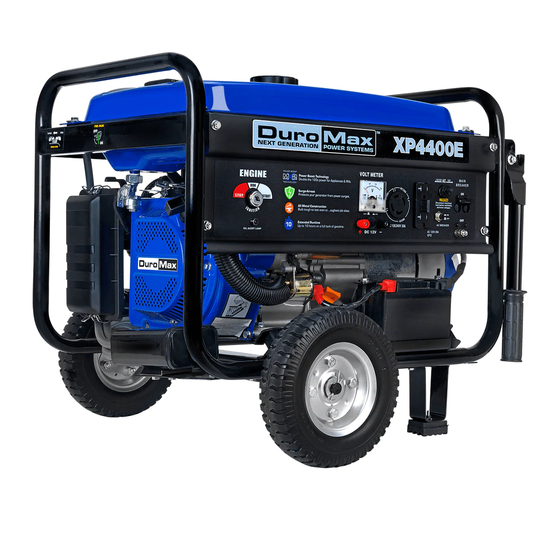
Gasoline Powered Generator
Owner's Manual
XP4400
D
XP4400E
D
customer_service@maxtool.com
or call 1-800-629-3325 (option 3) Monday -Thursday 6am to 7pm, Friday - Saturday 6am to 3pm. PST
support@maxtool.com
or call 1-800-629-3325 (option 3) Monday -Thursday 6am to 7pm, Friday - Saturday 6am to 3pm. PST
This manual provides information regarding the operation and maintenance of these products.
We have made every effort to ensure the accuracy of the information in this manual.
We reserve the right to change this product at any time without prior notice.
Advertisement
Table of Contents

Related Manuals for DUROMAX XP4400E


Summary of Contents for DUROMAX XP4400E
- Page 1 POWER SYSTEMS Gasoline Powered Generator Owner's Manual XP4400 XP4400E customer_service@maxtool.com or call 1-800-629-3325 (option 3) Monday -Thursday 6am to 7pm, Friday - Saturday 6am to 3pm. PST support@maxtool.com or call 1-800-629-3325 (option 3) Monday -Thursday 6am to 7pm, Friday - Saturday 6am to 3pm. PST This manual provides information regarding the operation and maintenance of these products.
- Page 2 FEATURES • Durable Hp, Air Cooled Overhead Valve Engine. • Heavy Duty Steel Frame with Four Point Fully Isolated Motor Mounts for Smooth and Quiet Operation. • Wheel and Handle Kit for Easy Transporting. • Full Power Panel with Engine Shutoff Switch, Volt Meter, Circuit Breaker and Power Outlets.
-
Page 3: Table Of Contents
TABLE OF CONTENTS GENERAL SAFETY PROCEDURES PACKAGE CONTENTS GENERATOR COMPONENTS PREPARING THE GENERATOR FOR USE Using the Generator for the First Time Step 1 - Add Oil Step 2 - Add Gasoline Step 3 - Ground the Generator Subsequent Use of the Generator Step 1 - Check the Oil Step 2 - Check the Gas Level Step 3 - Ground the Generator... -
Page 4: General Safety Procedures
GENERAL SAFETY PROCEDURES Please familiarize yourself with the following safety symbols and words: & is used with one of the safety words (DANGER, CAUTION, or The safety alert symbol WARNING) to alert you to hazards. Please pay attention to these hazard notices both in this manual and on the generator. - Page 5 & WARNING: This generator produces powerful voltage, which can result in electrocution. ALWAYS ground the generator before using it (see the "Grounding the Generator" portion of the "PREPARING THE GENERATOR FOR USE" section). Generator should only be plugged into electrical devices, either directly or with an extension cord.
- Page 6 In addition to the above safety notices, please familiarize your self with the safety and hazard markings on the generator. CAUTIONI POISONOUS GAS WARNINGl RISK OF EXPLOSION - Stop generator before refueling. Generator exhaust contains toxic - Check for spilled fuel. carbon monoxide gas.
-
Page 7: Package Contents
PACKAGE CONTENTS Your generator comes with the items listed below. Please check to see that all of the following items may be included with your generator, depending on your generator model. Screw driver Spanner Spark plug wrench... -
Page 8: Generator Components
GENERATOR COMPONENTS Please familiarize yourself with the locations and functions of the various components and controls of your generator. (1) Air cleaner- a removable, cleanable, sponge-like element that limits the amount of dirt pulled into the engine. (2) Choke lever- Adjusts the amount of air let into the engine. (3) Fuel Gauge- Indicates the amount of fuel in the tank. -
Page 9: Preparing The Generator For Use
1. When filling the engine with oil in the future, please refer to this chart. Model number XP4400 XP4400E Engine oil capacity 20 fluid oz. Figure 1- Generator Oil Capacity... -
Page 10: Step 2- Add Gasoline
Gas can age in the tank and make it hard to start up the generator in the future. • Never store generator for extended periods of time with fuel in the tank. Model number XP4400 XP4400E Gas tank capacity 15L(3.96 us. gallons) Figure 4 - Gas Tank Capacity Step 3- Ground the Generator... -
Page 11: Step 3 - Ground The Generator
WARNING: & Failure to properly ground the generator can result in electrocution. Ground the generator by tightening the grounding nut against a grounding wire (see figure 5). A generally acceptable grounding wire is a No. 12 AWG (American Wire Gauge) stranded copper wire. -
Page 12: Step 3- Ground The Generator
• Do not fill tank near an open flame. • Always allow engine to cool for several minutes before refueling. • Do not overfill (check the "Specifications" section for the tank capacity of your generator). Always check for fuel spills. IMPORTANT: •... -
Page 13: Using The Generator
4400 XP4400 3500 4400 XP4400E Figure 9-generator wattage by model number The total running wattage requirement of the electrical devices connected to the generator should not exceed the rated wattage of the generator itself. To calculate the total wattage requirement of the electrical devices you wish to connect, find the rated (or running) wattage of each device. - Page 14 If these specifications are not available you may estimate the Watts required by your device by using the chart in figure 10. Tool or Appliance Additional Surge Watts Rated (Running) Watts Electric water heater (40 gal) 4000 2500 Hot plate Saw-radial arm 2000 2000...
- Page 15 120V AC Receptacles 12V DC Receptacles Figure 11- Receptacles available on the generator VOLTAGE SELECTOR SWITCH (XP4400/XP4400E) The voltage selector switches the main power carrying windings of the generator to produce "120V ONLY" or If a 240V appliance is connected to the 4-prong receptacle, the "120/240V".
-
Page 16: Dc Usage
Device Requirements Max. Cord length (ft) by Wire Gauge Watts Watts Amps #8 wire #10 wire #12 wire #14 wire #16 wire (240V) (120V) 1000 1200 1800 1200 2400 1800 3600 2400 4800 3000 6000 3600 7200 4800 9600 *NR= not recommended Figure 12-Maximum Extension Cord lengths by Power Requirement DC Usage CAUTION:... -
Page 17: Stopping The Generator
If the generator you buy is electric start one, once beginning to work, it will charge the battery on the generator automatically. At this time, you can see the indication light is shining, after the battery is full, the light will be extinct. STOPPING THE GENERATOR To stop the generator: 1. -
Page 18: Checking The Oil
-A vacuum - Pressurized air Never clean your generator with a bucket of water or a hose. Water can get inside the working pats of the generator and cause a short circuit or corrosion. Checking the Oil The generator is equipped with an automatic shutoff to protect it from running on low oil. Nonetheless, you should check the oil level of the generator before each use to ensure that the generator crankcase has a sufficient amount. - Page 19 Model number XP4400 XP4400E Engine oil capacity 20 fluid oz. Figure 15- Engine Oil Capacity. It is only necessary to drain the oil from the crankcase if it has become contaminated with water or dirt. In this case, you can drain the oil from the generator according to the following steps: 1.
-
Page 20: Air Cleaner Maintenance
COVER AIR CLEANER SPRING COVER ELEMENT --+--- /::.J -----I-------_J \~" ------- 1.,--..==--_.- ---L 1---- ~_.-- '-y-- COVER SPRING Figure Removing the air cleaner casing. Fuel Filter Cup Cleaning The fuel filter cup is a small well underneath the fuel valve. It helps to trap dirt and water that may be in your fuel tank before it can enter the engine. -
Page 21: Emptying The Gas Tank
Pt.UG WRENCH - - " " - O. 7-{J.8 028-{J. 031 Figure Measuring the spark plug gap s·~ Figure 20- Removing the plug Emptying the Gas Tank Before storing your generator for extended periods of time, you should drain your generator of gasoline. -
Page 22: Specifications
GENERATOR SPECIFICATIONS AC Output XP4400 XP4400E Rated Wattage 3500W 3500W Surge Wattage 4400W 4400W Rated Voltage 120/240V 120/240V Rated Frequency 60Hz 60Hz Phase Single Single DC Output XP4400 XP4400E Voltage Amperage 8.3A 8.3A Length=23.2 Length=23.2 Dimensions (in): Width=17 Width=17 Height=17... -
Page 23: Generator Assembly And Mounting
(continued Move generator to a level surface to Generator is not on level from page prevent low oil shutdown from surface. triggering. Oil is low Add or replace oil. Set the circuit breaker to the "ON" Engine Circuit breaker is off. position. -
Page 24: Change The Carbon-Brush
Figure 25 Figure 26 Figure 27 Figure 28 CHANGE THE CARBON-BRUSH Dismantle the 2 bolts (M5X12) Take down the installed bolts Take down the carbon-brush of electric machine back-cover. (M5X 16) of carbon-brush. from DC wire of excitation. Install the new carbon-brush Insert and connect the DC Install the electric machine back with bolts (M5X16). -
Page 25: Wiring Diagram
Dismantle the 2 bolts (M5X12) Take down the 2 installed Disconnect the sample wire of electric machine back-cover. bolts (M5X16) of AVR. hindered. Take down the AVR from Install the new AVR with 2 Connect the sample wire carbon-brush bolts (M5X16) hindered. - Page 29 Item Part Part Description Item Description Set Pin, 10 x 14 DJ168F-16121-K Recoil Sarer DJ168F-11009-A GBT5787-B6-8 Bolt Flange M6x8 GB276-89-6205 Radial ball bearing (6025) DJ168F-16118 Grommet drain hole DJ168F-18500-A Spark Plug F7TC DJ168F-16120 Fan case OJ 170F-13009-A Tappet Litter Valve GBT61771/10-N-14 Flange nut M14 DJ 170F-13008-B...
- Page 31 Item Part Description Item Part Description DF2500H-31201-A Bottom rubber A 127 14306 Fuel filler cap comp DF2500H-31202-A Bottom rubber B 128 14303 Fuel sensor GBT6177-N-8 Flange nut M8 129 GBT819-B-5 Screw M5x10 GBT889-N-8 Flange nut M8 130 14313 GASKE~FUELSENSOR DF2500H-14304-A Rubber Screws, Fuel Tank Washer 14311...
- Page 33 Item Part Description Part Description Item DJ168F-16121-K Recoil Sarer DJ168F-11009-A Set Pin, 10x14 GBT5787-B6-8 Bolt Flange M6x8 GB276-89-6205 Radial ball bearing (6025) DJ168F-16118 Grommet drain hole DJ168F-18500-A Spark Plug F7TC DJ168FB-16120 Tappet Litter Valve Fan case DJ170F-13009-A GBT61771/1Q.N-14 Flange nut M14 DJ170F-13008-B Rod, push DJ168F-16000-A...
- Page 35 Description Description Item Part Part 125 DF2500H-14300-B 1 Fuel tank 84 XP4400E-31100-B 1 Frame comp 126 14307 1 Fuel filter DF2500H-31201-A Bottom rubber A 127 14306 1 Fuel filler cap comp DF2500H-31202-A Bottom rubber B 1 Fuel sensor GBT6177-N-8 Flange nut M8...
Need help?
Do you have a question about the XP4400E and is the answer not in the manual?
Questions and answers
What is the battery specified for this generator?
The specified battery for the DUROMAX XP4400E generator is the Mighty Max Battery YTX5L-BS.
This answer is automatically generated
Pictures of electrical wiring schematics
The electrical wiring schematic for the DUROMAX XP4400E includes:
- Wiring diagram for a 120V/240V generator set.
- Color codes used in the diagram:
- R: Red
- W: White
- GY or GR: Gray
- Y/G: Yellow/Green
The system includes:
- Main coil
- DC coil
- LED indicator
- Ignition switch
- AVR (Automatic Voltage Regulator)
- Carbon brush
- Excitation wires (connected according to anode and cathode)
The diagram also shows connections between parts like the recoil starter, spark plug, radial ball bearings, and bolts for assembly.
This answer is automatically generated