
Related Manuals for TECO-Westinghouse Motor EV INVERTER Series


Summary of Contents for TECO-Westinghouse Motor EV INVERTER Series
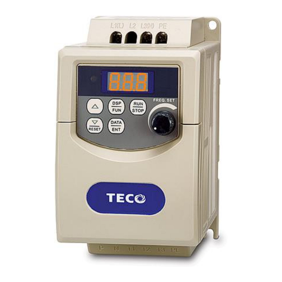
- Page 1 EV INVERTER SERIES Operating Manual 110V 1Ø 0.2 - 1HP 0.2 – 0.75kW 230V 1Ø /3Ø 0.2 - 3HP 0.2 – 2.2kW 460V 3Ø 1 - 3HP 0.75 – 2.2kW Revision: 1.04.00...
-
Page 2: Table Of Contents
17 - 20 Table 10.2 C (Advanced) Parameters………………………………. 21 - 26 Section 11 Parameter Description (Basic) and C (Advanced) …………………. Basic……………………………………………………………………… 27 - 42 Advanced………………………………………………………………… 43 - 53 Section 12 Envelope and Dimensional Tables…………………………………..___________________________________________________________________________ TECO – Westinghouse Motor Company... - Page 3 Table 13.5 Keypad Errors ……………………………………………..… Appendix A Inverter Specifications................Inverter Basic Specifications..............60 – 62 Inverter General Specifications............. 63 – 66 Appendix B NEMA 4 Installation and Wiring............Appendix C Inverter Parameter Setting List............Warranty……………………………………………………………………………………… ___________________________________________________________________________ TECO – Westinghouse Motor Company...
-
Page 4: Introduction
EV Inverter Operating Manual Introduction The EV Inverter series is state of the art design using the latest control and power technologies. It is designed to operate and control 3Ø induction motors in the range of 0.25 to 3hp and voltage class of 230 or 460VAC. -
Page 5: Installation And Pre-Operation
F04=001 external terminal (switch) is on and parameters F41=000. (Auto Restart after power loss) When removing or installing the keypad operator, turn OFF power first, and follow the instruction diagram to avoid improper operation. ___________________________________________________________________________ TECO – Westinghouse Motor Company... -
Page 6: Input Power
Output Power terminal information NOTES: 1 - Digital inputs S1,S2,S3,S4, & S7 are Braking shown. Digital inputs S5 & S6 Unit provided with a plug-in option module Fig. 1 EV Inverter Pictorial Wiring Diagram ___________________________________________________________________________ TECO – Westinghouse Motor Company... -
Page 7: Section 2 Inverter Option Modules
PD A C a b le I nt erf ac e Option Cards Plug into Connector Con 302 (SIF-IO Module shown) Fig . 2 .1 O pt ion C a rd Ins ta ll ati on an d W ir i ng ___________________________________________________________________________ TECO – Westinghouse Motor Company... -
Page 8: Fig. 2.4 Copy Module (P/N Sif-Mp)
PC and option card to avoid equipment Series damage. CON302 SIF-232 RS232 Fig. 2.3 RS232 Interface P/N SIF-232 1Ø / 3Ø Input Voltage EV Inverter Series CON302 SIF-MP Fig. 2.4 Copy Module P/N SIF-MP ___________________________________________________________________________ TECO – Westinghouse Motor Company... -
Page 9: Fig. 2.5 Remote Keypad (P/N Sdop-Led-2M)
Fig. 2.6 I/O Module P/N SIF- IO 1Ø / 3Ø P/N JNSWPDA Input Voltage PDA Wire EV Inverter RS232 Series CON302 SIF-232 HP iPAQ Pocket PC h2210. (PDA) / PC hx2190 Fig. 2.7 PDA Link ___________________________________________________________________________ TECO – Westinghouse Motor Company... -
Page 10: Section 3 Control Signal Terminal Block Description
NOTE : Logic level high; => +8V* logic level low level; =< 2V *Caution! Do not exceed 10V maximum. Output common - Same as terminal 8 Multi – function analog output 0 – +10VDC, Refer to parameter F26 (000-005) for output functions. ___________________________________________________________________________ TECO – Westinghouse Motor Company... -
Page 11: Section 4 Input Power Terminal Block Description
Power Output Terminal Designations Terminal Description Designation DC Power and braking unit Inverter power output (Motor connections) *3Ø (Three Phase) 0 – 200Hz Max. Earth ground Caution - *Refer to the inverter nameplate for output voltage specifications ___________________________________________________________________________ TECO – Westinghouse Motor Company... -
Page 12: Section 6 Peripheral Power Devices
To avoid damaging the inverter, do not connect the input terminals T1, T2, and T3 to AC input power. Induction Motor Connect the ground terminal properly.( 230V series: Rg <100; 460V series: Rg <10.) ___________________________________________________________________________ TECO – Westinghouse Motor Company... -
Page 13: Section 7 Fuse Types And Ratings
Max.CC or T JNEV- Output AMPS FUSE FUSE Rating(A) Rating(A) 401-H3 0.75 402-H3 403-H3 Note: Fuse ratings are based upon 300V fuses for 120V inverters, 300V fuses for 230V inverters, and 500V for 460V inverters. ___________________________________________________________________________ TECO – Westinghouse Motor Company... -
Page 14: Section 8 Quick Start Guide
Press the RUN /STOP key, and observe the motor operation as it accelerates to full speed. Press the RUN/STOP key, and observe the motor operation as it decelerates to 0 speed. After satisfying the above, you can proceed with setting the application specific parameters and permanent installation. ___________________________________________________________________________ TECO – Westinghouse Motor Company... -
Page 15: Section 9 Keypad Key Functions And Navigation
UP / DOWN save the various parameters with the keys and to updated parameter settings. Local · Used in conjunction with the DOWN / RESET key to toggle between Remote operation. ___________________________________________________________________________ TECO – Westinghouse Motor Company... -
Page 16: Keypad Navigation
The RUN command is controlled via the function set by (F04) The frequency command is set by the function set by (F05) DATA To toggle between Local / Remote press the keys simultaneously. RESET ___________________________________________________________________________ TECO – Westinghouse Motor Company... -
Page 17: Setting Parameters F (Basic) And C (Advanced)
Returns to Advanced menu Advanced DATA DATA parameters Display flashing displayed Parameter Scroll from Scroll to function function or value C00 to C55 or code saved RESET Fig. 9.4.1 Set F (Basic) and C (Advanced) Parameters ___________________________________________________________________________ TECO – Westinghouse Motor Company... -
Page 18: Section 10 Parameters F (Basic) And C (Advanced)
- Parameters F (Basic) and C (Advanced) Function Tables Overview – The EV Inverter Series is program capable to allow for a variety of application requirements. The parameters are split into two categories, F and C. The F parameters set the Basic functions of the inverter while the C parameters control the more Advanced functions. - Page 19 AIN bias (%) Positive Note 1 *F19 AIN bias Negative Positive *F20 AIN slope direction Negative * Parameters F16 – F20 are used when F15 is selected as an analog input 017 or 018 ___________________________________________________________________________ TECO – Westinghouse Motor Company...
- Page 20 Preset frequency 6 (Hz) 00.0 - 200 50.0 Note 1&2 Preset frequency 7 (Hz) 00.0 – 200 Preset frequency 8 (Hz) 60.0 Note 1&2 00.0 – 200 Jog frequency setting (Hz) 05.0 Note 1&2 ___________________________________________________________________________ TECO – Westinghouse Motor Company...
- Page 21 5 - Please consult factory before making any parameter adjustments 6 - Changed in Software version 1.5 or later 7 – Default setting for North American units is to the right of the /; setting for all other units are to the left. ___________________________________________________________________________ TECO – Westinghouse Motor Company...
-
Page 22: Table 10.2 C (Advanced) Parameters
Reset mode Whether RUN instruction is OFF or ON, the reset command is always available 00.1 – 999 Notes 1&2 Acceleration time 2 (sec.) 05.0 00.1 – 999 05.0 Notes 1&2 Deceleration time 2 (sec.) ___________________________________________________________________________ TECO – Westinghouse Motor Company... - Page 23 (OL1) Disable motor protection 00.0 - 200 00.0 Note 1&2 Skip frequency 1(Hz) Skip frequency 2(Hz) 00.0 - 200 00.0 Note 1&2 Skip frequency range (±Hz) 00.0 - 30.0 00.0 Note 1 ___________________________________________________________________________ TECO – Westinghouse Motor Company...
- Page 24 UP/Down command is Frequency Up/Down available. Set frequency control using MFIT resets to 0Hz when inverter stops. UP/Down command is available. Set frequency is held when inverter stops. Up/Down is available when stopped. ___________________________________________________________________________ TECO – Westinghouse Motor Company...
- Page 25 S5 and PID Feedback signal (terminal AIN) DC Injection brake signal Multi-function input terminals S1-S6 signal scan time 001 - 100 (mSec ×8) AIN signal scan time 001 - 100 (mSec x 8 ) ___________________________________________________________________________ TECO – Westinghouse Motor Company...
- Page 26 Notes 3&4 19200 required 38400 1 Stop bit Stop bit Note: SIF-232 or Notes 3&4 SIF-485 required 2 Stop bits No parity Parity bit Note: SIF-232 or Notes 3&4 Even parity SIF-485 required Odd parity ___________________________________________________________________________ TECO – Westinghouse Motor Company...
- Page 27 7 - Default setting for North American units is to the right of the /; setting for all other units are to the left. 8 - Please consult factory before making any parameter adjustments ___________________________________________________________________________ TECO – Westinghouse Motor Company...
-
Page 28: Section 11 Parameter Description (Basic) And C (Advanced)
001: Potentiometer on keypad F05 Frequency signal source 002:TM2 input signal (Terminal AIN) 003: Multi-function input terminal UP/DOWN function 004: Frequency set by communication method ( NOTE: When C47=1, the remote keypad has priority) ___________________________________________________________________________ TECO – Westinghouse Motor Company... - Page 29 S3 (Forward / Reverse) S3 (Forward / Reverse) COM (Common) +24V (Common) Fig. 11.1c 3- Wire Run / Stop NOTE: In 3 wire control mode, terminals S1-S3 are dedicated, therefore parameters F11 - F13 are ineffective. ___________________________________________________________________________ TECO – Westinghouse Motor Company...
- Page 30 1.) F09 = 000: after receiving a stop command, the motor will decelerate to stop at the rate set in F02, deceleration time 1. 2.) F09 = 001: after receiving a stop command, the motor will free-run (Coast) to stop. ___________________________________________________________________________ TECO – Westinghouse Motor Company...
- Page 31 Jog speed and is active (On), the inverter will run at the frequency programmed in the F36 setting. (See table on next page) NOTE: Priority of the frequencies: Jog > Preset Speed ___________________________________________________________________________ TECO – Westinghouse Motor Company...
- Page 32 F09. The inverter will accelerate from 0Hz each time a run command is given. NOTE: The Up / Down commands are disabled if both Up and Down terminals are ON at the same time. ___________________________________________________________________________ TECO – Westinghouse Motor Company...
- Page 33 The PID feedback signal can be connected to the analog input terminal AIN 0-10VDC / 0 - 20mA or 2 - 10VDC / 4 - 20mA as set by F16 and switch, SW2 (select between 0-10VDC or 0/4-20mA). ___________________________________________________________________________ TECO – Westinghouse Motor Company...
- Page 34 Fig 11.4b setting: 100% 050% 100% 050% 100% 000% 100﹪ 000% Bias Bias Upper frequency limit Upper frequency limit 100% 100% (F07=60.0) (F07=60.0) 050% 30Hz 050% 000% 0.00% (4mA) (20mA) (4mA) (20mA) Fig 11.4a Fig 11.4b ___________________________________________________________________________ TECO – Westinghouse Motor Company...
- Page 35 011: Inverter overload protection 012: Not used 013: Power on 014: Communication error 015: Output current detection (>F24) F22 Preset output frequency 00.0 - 200Hz target F23 Target frequency 00.0 - 30Hz detection range ___________________________________________________________________________ TECO – Westinghouse Motor Company...
- Page 36 If Inverter is Stopped or has no Reference Frequency the Relay will not Operate Fig. 11.5b Multi-function Output (F21 / C46 = 002) Preset output frequency (F22 ± F2 3) R e ac he d. ___________________________________________________________________________ TECO – Westinghouse Motor Company...
- Page 37 (F22) Relay Output Signal The Relay Output is always active when the inverter is stopped Fig. 11.5d (F21/C46=004) F r equ en c y d et ect ion Fo ut < F2 2 ___________________________________________________________________________ TECO – Westinghouse Motor Company...
- Page 38 1) F11 - F15=002-004: Preset frequency Command 1 - 3 When the run signal is applied and any of the selected multi-function input terminals are ON, the inverter will run at the preset frequency per the table on the next page. ___________________________________________________________________________ TECO – Westinghouse Motor Company...
- Page 39 NOTE: DC braking is enabled / disabled by multifunction input setting as described on page 33 F37 / F38: DC braking time and start frequency, per the following figure: Brake Signal F11 – F15=019 Fig. 11.7 DC Injection Braking ___________________________________________________________________________ TECO – Westinghouse Motor Company...
- Page 40 3.) Auto restart is not available for OL1, OL2, OH, and bb faults. NOTE: Auto restart will not function when DC injection braking or deceleration to stop are performed. F43 Motor rated current : (A) F44 Motor rated voltage : (VAC) ___________________________________________________________________________ TECO – Westinghouse Motor Company...
- Page 41 F49 at the same time. (See Fig. 11.9) Slip compensation gain (vector mode), C14=000 (Control mode setting) Performance: If the motor load is excessive, increase the slip compensation. ΔF ≒ Gain slip (Load current) (Compensation gain) ___________________________________________________________________________ TECO – Westinghouse Motor Company...
- Page 42 Operating frequency range: 0 - 10Hz / 50Hz • During low frequency operation: When the motor output torque is insufficient, increase the value of F50. When the motor is vibrating excessively, decrease the value of F50. ___________________________________________________________________________ TECO – Westinghouse Motor Company...
- Page 43 To return to F parameters / Output Frequency Ref e r t o se ct ion 1 3 f or an ex pl an atio n o n the E r ro r/ Fa ult Co de s ___________________________________________________________________________ TECO – Westinghouse Motor Company...
- Page 44 ON. Danger This feature should only be considered when all safety implications of its use have been investigated. (Risk assessment for maintenance, use of warning labels etc.) We recommend this mode to be disabled. ___________________________________________________________________________ TECO – Westinghouse Motor Company...
- Page 45 V (%) (V max) (V mid) (V min) Fig. 11.11a User configured V / f pattern ___________________________________________________________________________ TECO – Westinghouse Motor Company...
- Page 46 EV Inverter Operating Manual C15 = 001– 006 fixed V / f patterns (see below). V / f Pattern V / f Pattern Fig. 11.11b Pre-configured V / f patterns ___________________________________________________________________________ TECO – Westinghouse Motor Company...
- Page 47 C25 Motor no load current : (A) Motor no load current varies with inverter capacity F00. Adjust according the actual conditions. 000: Protection Enabled C26 Electronic thermistor protection for motor (OL1) 001: Protection Disabled ___________________________________________________________________________ TECO – Westinghouse Motor Company...
- Page 48 C33 I: Integral time (s) : 00.0 – 100 C33: Integral time for I control (NOTE: To increase integral action, decrease the integral time setting.) C34 D: Differential time (s) : 0.00 - 10.0 C34: Differential time for D control. ___________________________________________________________________________ TECO – Westinghouse Motor Company...
- Page 49 (C39), the inverter output will decelerate to zero speed (Sleep mode). When the PID output frequency becomes higher than the sleep start frequency (C38), the inverter output accelerates to PID output frequency (Wake mode). Refer to Fig. 11.14 on the next page. ___________________________________________________________________________ TECO – Westinghouse Motor Company...
- Page 50 C40=000, except when restarted, the inverter always ramps up from 0Hz. 3) C40=002: Same as for C40=001 except the Up / Down is available while in stop mode to adjust the set frequency. ___________________________________________________________________________ TECO – Westinghouse Motor Company...
- Page 51 3.) The user can set scan interval times according to the noise in the operating environment. Extend the values of C44/C45 if noise is a problem, however this will reduce the signal response time. ___________________________________________________________________________ TECO – Westinghouse Motor Company...
- Page 52 NOTE: Module copy function is applicable only to inverters with the same voltage and kW rating. C49 Inverter communication address: 001 - 254 C49 sets the communication address, for the specific inverter when multi-inverters are controlled. ___________________________________________________________________________ TECO – Westinghouse Motor Company...
- Page 53 000: Deceleration to stop (F02: Deceleration time 1). 001: Free run (coast) to stop. 002: Deceleration to stop (C12: Deceleration time 2). 003: Continue operating. Default=000 *Cannot be modified when in serial communication mode. ___________________________________________________________________________ TECO – Westinghouse Motor Company...
- Page 54 ―COT‖ until Reset C55=003 ―COT‖ Display Reset or Master send data 0,1,2,3 Reset Master Command Run Command (only F04=002) Communication mode NOTE : COT = communication time out fault Fig. 11.15 Communication error timing pattern ___________________________________________________________________________ TECO – Westinghouse Motor Company...
-
Page 55: Section 12 Envelope And Dimensional Tables
JNEV – 403 – H3 .177/4.5 Dia. Mounting ( Qty 4) surface Dimensions Inches / mm Frame Size 5.2/132 3.03/77 5.13/130.5 0.17/4.3 4.86/123.5 0.20/5 2.64/67 0.315/8 5.2/132 4.65/118 5.83/148 0.17/4.3 4.86/123.5 0.20/5 4.25/108 0.315/8 ___________________________________________________________________________ TECO – Westinghouse Motor Company... -
Page 56: Section 13 Error Codes And Troubleshooting
2. Improve ventilation conditions or or poor ventilation relocate inverter Current transducer Current transducer or circuit detection error Repair or replace unit error. * The Fault relay contact does not operate with these error indications. ___________________________________________________________________________ TECO – Westinghouse Motor Company... -
Page 57: Table 13.2 Automatically And Manually Recoverable Errors
2. Increase inverter capacity Excessive heat sink 3. Improve ventilation conditions temperature during 2. Ambient temperature too high or operation poor ventilation 4. Check the setting value of parameter C13 ___________________________________________________________________________ TECO – Westinghouse Motor Company... - Page 58 The inverter will decelerate to stop and flashes E.S. when there is External emergency stop an external emergency stop signal via the Control input terminals E.S. (see parameters F11-F14). ___________________________________________________________________________ TECO – Westinghouse Motor Company...
- Page 59 HP ratings. 1. Change Copy unit Copy the parameter to 2. The voltage and HP rating of Parameters do not match inverter to verify the Copy unit is different than the parameter not matched. inverter. ___________________________________________________________________________ TECO – Westinghouse Motor Company...
-
Page 60: Appendix A Inverter Specifications
Inverter weight lb (kg) 3.31 3.35 3.42 (1.26) (1.29) (1.34) Inverter with filter weight lb 3.70 3.75 3.82 (1.37) (1.4) (1.45) (kg) Maximum momentary power loss time (sec.) Enclosure IP20 * Based on a 4-Pole Motor ___________________________________________________________________________ TECO – Westinghouse Motor Company... -
Page 61: Inverter General Specifications
1G (9.8m/s Built-in class B / external: class A, accordance with EN61800-3 first non EMI / EMS Compatibility limit / limit environment Accordance with EN50178 Enclosure IP20 Safety Class UL508C Inverter General Specifications Con’t ___________________________________________________________________________ TECO – Westinghouse Motor Company... - Page 62 EV-2P2-201-H1F type (Carrier frequency =10KHz) with built-in filter complies with EN61800-3 first environment unrestricted distribution. (IP65) EV-2P2-403-H1(3)FN4(S) series & EV- 401- 403-H3F type (Carrier frequency=10KHz) With built-in filter & EV-202-203-H1F type (Carrier frequency =10KHz) complies with EN61800-3 first environment restricted distribution. ___________________________________________________________________________ TECO – Westinghouse Motor Company...
-
Page 63: Appendix B Nema 4 Installation And Wiring
REV – 0 – FWD switch to 0 position +10V so that the drive has no run signal before power- up. Otherwise injury may result. Potentiometer brown orange green black yellow Fig. B.2 JNEV NEMA4 Wiring Diagram ___________________________________________________________________________ TECO – Westinghouse Motor Company... - Page 64 Otherwise injury may result. TM2 202/203 TM2 401/402/403 brown orange green green orange brown black yellow black yellow Fig. B.4 JNEV NEMA4 Wiring Diagram ___________________________________________________________________________ TECO – Westinghouse Motor Company...
- Page 65 Plug-in Terminals Power Terminal Block (TM1) Frequency Control Power Supply FWD / REV Cable L1 – L2 Motor Cable T1-T2-T3 Fig. B.5 M/N JNEV – YYY – H1FN4 & H1FN4S (115VAC and 230VAC) Connection Diagram ___________________________________________________________________________ TECO – Westinghouse Motor Company...
- Page 66 IP65 Frame 2 (*switch) JNEV-202/203/401/402/403 – H3FN4FS 8.27 in. 210 mm * switch not shown 8.27 in. 210 mm 11.61 in. 9.09 in. 295 mm 231 mm 0.20 in. 5.0 mm Fig. B.7 EV NEMA4S Frame 2 ___________________________________________________________________________ TECO – Westinghouse Motor Company...
-
Page 67: Appendix C Inverter Parameter Setting List
EV Inverter Operating Manual – EV Parameter Setting List Appendix C Customer: EV Model No. Site: Equipment: F (Basic) Parameters C (Advanced) Parameters Parameter Setting Parameter Setting Parameter Setting Parameter Setting NOTES: ___________________________________________________________________________ TECO – Westinghouse Motor Company... -
Page 68: Warranty
All Low Voltage Motor Control Products, such as Solid State Starters and Inverters, (―products‖) sold by TECO-Westinghouse Motors Company (―TWMC‖), are warranted to be free from defects in material and workmanship for a period of 24 months from the date of shipment. A warranty of 36 months from the date of manufacture is applicable when a TWMC Low Voltage Motor Control Product and a TWMC Inverter Duty motor (per NEMA MG1-31.4.2.2) are purchased together.
Need help?
Do you have a question about the EV INVERTER Series and is the answer not in the manual?
Questions and answers