Table of Contents
Advertisement
Installation Manual
MA7200
AC Inverter
208 to 230V
380 to 460V
1 / 3 Phase
3 Phase
3 Phase
4H358D0180009
1 ~ 3HP
5 ~ 40HP
1 ~ 75HP
Advertisement
Table of Contents
Troubleshooting

Related Manuals for TECO-Westinghouse Motor MA7200


Summary of Contents for TECO-Westinghouse Motor MA7200
- Page 1 4H358D0180009 Installation Manual MA7200 AC Inverter 208 to 230V 1 / 3 Phase 1 ~ 3HP 3 Phase 5 ~ 40HP 380 to 460V 3 Phase 1 ~ 75HP...
- Page 2 “CHARGE” LED is extinguished. Never connect power circuit output U/T1, V/T2, W/T3 to AC power supply. CAUTION When mounting the MA7200 in a separate enclosure, install a fan or other cooling device to keep the intake air temperature below 113 F (45 Do not perform a withstand voltage test to the inverter.
-
Page 3: Parameter Setting
Contents Page 1. MA7200 Handling Description ------------------------------------- 1-1 1.1 Inspection Procedure upon Receiving ---------------------------------------- 1-1 1.2 Installation ------------------------------------------------------------------------ 1-2 1.3 Removing/Attaching of LCD Digital Operator and Front Cover---------- 1.4 Wiring between Inverter and Peripheral Devices --------------------------- 1.5 Description of Terminal Function -------------------------------------------- 1-11 1.6 Main Circuit Wiring Diagram... - Page 4 Figure Contents Page No. Figure Contents Page Air clearance for MA7200 wall mounting 27 S curve 3-27 Standard connection diagram 28 ASR Integral Gain 2 3-28 Processing the ends of twisted-pair cables 1-15 29 Deceleration to stop 3-44 The optical-couplers connect to external...
-
Page 5: Ma7200 Handling Description -------------------------------------
1. MA7200 Handling Description 1.1 Inspection Procedure upon Receiving Before delivery, Every MA7200 inverter has been properly adjusted and passed the demanding function test. After receiving the inverter, the customer should take it out and follow the below procedure: • Verify that the Type No. of the inverter you’ve received is the same as the Type No. -
Page 6: Installation ------------------------------------------------------------------------
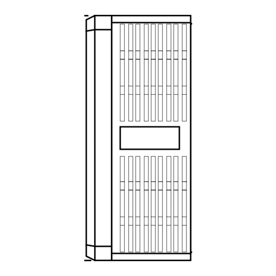
50 mm min. 120 mm min. ambient temperature -10 ~ + 40 ℃ 30 mm 120 mm 30 mm min. 50 mm min. min. min. (a) Space in Side (b) Space in Top/bottom Fig. 1-a. Air clearance for MA7200 wall mounting... - Page 7 Fig. 1-b. MA7200 NEMA4 Installation CAUTION Location of equipment is important to achieve proper performance and normal operating life. The MA7200 inverter should be installed in area where the following conditions exist. Ambient temperature: +14 to 104 F, (-10 to 40 Install the MA7200 in a location protected from rain, moisture and direct sunlight.
- Page 8 1.3 Removing/Attaching the Digital Operator and Front cover CAUTION Please disassemble Front Cover before you connect wires to terminals on MA7200 models. • 230V 1~25HP & 460V 1~30HP models: Plastic instructions, so please disconnect LCD Digital Operator before you disassemble Front Cover. After you finished the wiring connection, assemble Front Cover first then reinstall LCD Digital Operator.
- Page 9 (B) For 230V : 3-10HP, 460V : 3-10HP MA7200-2003-N1 MA7200-4003-N1 MA7200-2005-N1 MA7200-4005-N1 MA7200-2007-N1 MA7200-4007-N1 MA7200-2010-N1 MA7200-4010-N1 Removing the digital operator ■ Take off the screws in the place a. and b. LCD Digital Operator Front Cover Press the lever on the side of the digital operator in the direction of arrow 1 to unlock the digital operator.
- Page 10 (C) For 230V 15,20HP and 460V 15,20HP Series MA7200-2015-N1 MA7200-4015-N1 MA7200-2020-N1 MA7200-4020-N1 ■ Removing digital operator LCD Digital Take off the screws in the place a. and b. Operator Disconnect the RS-232 cable connector on the back side of the LCD digital operator and then lift the digital operator upwards.
-
Page 11: Wiring Between Inverter And Peripheral Devices ---------------------------
1.4 Wiring between Inverter and Peripheral devices and notice CAUTION 1. After turning OFF the main circuit power supply, do not touch the circuit components or change any circuit components before the “CHARGE” lamps extinguished. (It indicates that there is still some charge in the capacitor). 2. - Page 12 Example of connection between the MA7200 and typical peripheral devices are shown as below. MCCB (Molded-Case Circuit Breaker) Power supply Choose the Molded Case Circuit Breaker (MCCB) of proper current rating. Please refer to the selection guide Power supply “1.10 Peripheral Units” on Page 1-22.
-
Page 13: Standard Connection Diagram
■ Standard Connection Diagram The standard connection diagram of MA7200 is shown in Fig. 2. The sign ◎ indicates the main circuit terminal and the sign ○ indicates control circuit terminal. The terminal function and arrangement are summarized in Table 1 and Table 2. There are three types of control board, the terminal arrangement is shown as below. - Page 14 (B) 230V : 3-40HP, 460V : 3-75HP (NEMA4 to 20HP) MA7200-2003-N1 MA7200-4003-N1 through through MA7200-2040-N1 MA7200-4075-N1 Braking Resistor B1/P R/L1 U/T1 Main Ckt S/L2 V/T2 Power Supply T/L3 W/T3 Grounding Lead (<100 Ω ) Analog FWD/STOP ("Close":FWD) Output 1 Analog Monitor 1, 2...
-
Page 15: Terminal Block Configuration
1.5 Description of terminal function Table 1 Main circuit terminals Terminal 230V:1~20HP, 460V:1~20HP 230V:25~40HP, 460V:25~75HP R/L1 Main circuit input power supply S/L2 (For single phase power supply, please use R/L1, S/L2 as input terminal) T/L3 B1/P B1/P, B2: External braking resistor B1/P, Θ: DC power supply input •... -
Page 16: Control Circuit Terminals
Table 2 Control circuit terminals Terminal Functions 1(DI1) Forward Operation – Stop Signal 2(DI2) Reverse Operation – Stop Signal 3(DI3) External Fault Input 4(DI4) Fault Reset 5(DI5) Multifunction Input Terminal: 3-Wire Operation, Load/Remote Control, Multi-Speed Select, 6(DI6) FWD/REV Select, ACC/DEC Choice, ACC/DEC Halting, Base Block, Overheat Warn, PID 7(DI7) Control, DC Braking, Speed Search, Up/Down Function, PG Feedback Control, External Fault, Timer function, Multifunction Analog Input Setting... - Page 17 Main Circuit Wiring Diagram Main Circuit Wiring Diagram of MA7200: 1. 230V/460V : 1~20HP 2. 230V : 25HP 460V : 25~30HP 3. 230V : 30~40HP 460V : 40~75HP 1-13...
-
Page 18: Main Circuit Wiring
■ Main circuit wiring The non-fusible-breaker (NFB) should be installed between the AC source and the R/L1-S/L2-T/L3 input terminal of MA7200 inverter. The user can make his own decision of installing electromagnetic contactor block (MCB) or not. To protect against the false triggering of leakage-current, the user should install a leakage current breaker with amperage sensitivity≧200mA and operation time≧0.1 sec. - Page 19 50 mA max. 48V max. free-wheeling diode (100V, >100mA) MA7200 external wiring circuit 7200MA Fig. 4. The Optical-couplers connect to external inductive load (B) Wiring the main circuit terminals: (1) Input power supply can be connected to any terminal R/L1, S/L2 or T/L3 on the terminal block.
- Page 20 (b) OK (c) NO Fig. 5. MA7200 ground winding • Determine the wire size for the main circuit so that the line voltage drop is within 2% of the rated voltage. (If there is the possibility of excessive voltage drop, use a larger wire suitable to the required length) •...
-
Page 21: Inverter Specifications
1.8 Inverter Specifications Basic Specifications (a) 230V Series Inverter (HP) Max. Applicable Motor Output HP (KW) (0.75) (1.5) (2.2) (5.5) (7.5) (11) (15) (18.5) (22) (30) Rated Output 10.1 13.7 20.6 27.4 Capacity (KVA) Rated Output 17.5 Current (A) Max. Output Voltage 3-Phases, 200V~230V Max. -
Page 22: General Specifications
General Specifications Graphic LCD Panel (English and Chinese) with parameters copying (LED: Operation Mode option) Control Mode Sinusoidal PWM Frequency Control Range 0.1Hz ~ 400Hz Frequency Accuracy Digital Command: ±0.01% (-10 ~ +40ºC), (varied with temperature) Analog Command: ±0.1% (25ºC±10ºC), Speed Control Accuracy ±0.1 %... -
Page 23: Dimensions ----------------------------------------------------------------------
1.9 Dimensions Open Chassis Type (IP00) Inverter Weight Enclosed Type (NEMA1) (mm) Weight Reference (mm) Voltage Capacity(HP) (kg) (kg) Figure D W1 H1 W1 H1 132 217 143.5 122 207 M5 230V 1/3Φ 140 279.5 176.5 126 226 M6 140 279.5 176.5 126 226 M6 211.2 300 215 192 286 M6 230V 3Φ... - Page 24 (b) 230V : 3HP~25HP 460V : 3HP~30HP (c) 230V : 30HP~40HP 460V : 40HP~75HP ( -IP00) ( -NEMA1) Open Chassis Type Enclosed, Wall-mounted Type (d) NEMA4 Type : 1HP~20HP 1-20...
- Page 25 NEMA4 (mm) Inverter Weight Voltage Capacity(HP) (kg) 230V 1/3Φ 230V 3Φ 460V 3Φ 1-21...
- Page 26 1-22...
- Page 27 1.10 Peripheral Units ■ Braking resistors MA7200 230V/460V 1~20HP model have built-in braking transistor, and can be connected external braking resistor between B1/P and B2 when lack of braking ability. Above 25HP models, need to connect braking unit (on ⊕ - of inverter) and braking resistors (on B-P0 of braking unit).
-
Page 28: Ac Reactor List
■ AC reactor • An AC reactor can be added on the power supply side if the inverter is connected to a much larger capacity power supply system, or the inverter is within short distance (<10m) from power supply systems, or to increase the power factor on the power supply side. -
Page 29: Noise Filter On The Input Side
• Installing a noise filter on power supply side to eliminate noise transmitted between the power line and the inverter • MA7200 has its specified noise filter to meet the EN61800-3 class A specification Table 6 Noise filter on the input side... - Page 30 • Dimension : (unit : mm) φ 2 − φ 4 − Dimension (mm) Model KMF370A KMF3100A KMF3150A KMF3180A 1-26...
- Page 31 B. EMI SUPPRESSION ZERO PHASE CORE • Model : JUNFOC046S ------- • Code No. : 4H000D0250001 • According to the required power rating and wire size, select the matched ferrite core to suppress EMI noise. • The ferrite core can attenuate the frequency response at high frequency range (from 100KHz to 50MHz, as shown below).
- Page 32 ■ LCD operator with extension wire When used for remote control purpose, the LCD operator can have different extension wires based upon the applications. Some extension wires are listed below. MA7200 Cable Length Extension Cable Set *1 Extension Cable *2...
- Page 33 Analog Operator portable operator. The wiring diagram is shown below. Fig. 7. Analog Operator ■ PROFIBUS Communication Card • Code No. : 4H300D0290009 • Please refer to the appendix D and “MA7200 PROFIBUS-DP Communication Application manual” for communication interface. 1-29...
-
Page 34: Using Lcd Digital Operator-----------------------------------------
2. Using LCD Digital Operator ■ Functions of LCD digital operator JNEP-36 LCD digital operator has 2 modes: DRIVE mode and PRGM mode. When the inverter is stopped, DRIVE mode or PRGM mode can be selected by pressing PRGM the key . -
Page 35: Key's Functions
Table 7 Key's functions Name Function PRGM/DRIVE Switches over between program mode (PRGM) and drive PRGM DRIVE mode (DRIVE). DSPL DSPL key Display operation status Enable jog operation from LCD digital operator in operation JOG key (DRIVE). FWD/REV Select the rotation direction from LCD digital operator. Set the number of digital for user constant settings. - Page 36 ■ Display contents in DRIVE mode and PRGM mode Power on PRGM mode PRGM DRIVE mode DRIVE DSPL DSPL Frequency reference monitor/set □ □ value displayed DSPL DSPL display monitor/set item monitor/set □ □ DSPL DSPL monitor/set monitor □ □ □...
-
Page 37: Parameter Description
■ Parameter description The inverter has 4 groups of user parameters: Parameters Description An-□□ Frequency command Bn-□□ Parameter groups can be changed during running Sn-□□ System parameter groups (can be changes only after stop) Cn-□□ Control parameter groups (can be changed only after stop) The parameter setting of Sn-03 (operation status) will determine if the setting value of different parameter groups are allowed to be changed or only to be monitored, as shown below:... -
Page 38: Operation Mode
■ Example of using LCD digital operator Note : Before operation: Control parameter Cn-01 value must be set as the input AC voltage value. For example, Cn-01=380 if AC input voltage is 380. This example will explain the operating of the inverter according to the following time chart. - Page 39 Key Sequence Digital Operator Description Remark Display (continued) Freq. Cmd.000.00Hz DRIVE PRGM Select DRIVE mode TECO DRIVE FWD JOG Select output frequency Freq. Cmd.0.00 Hz DSPL O/P Freq. 0.00 Hz displayed Select direction of rotation (When power on, initially defaulted FWD) O/P Freq.
- Page 40 ■ Example of display (use keys to display monitored items/contents) Digital Operator Key Sequence Description Remark Display Display Freq. Cmd. 60.00Hz TECO Frequency Command Display Freq. Cmd. 60.00 Hz DSPL O/P Freq. 60.00 Hz Moniter Contents *1 Display Freq. Cmd. 60.00 Hz O/P I 12.5 A Output Current...
- Page 41 3. Parameter Setting Frequency command (in Multi-speed operation) -□□ Under the DRIVE mode, the user can monitor the parameters and set their values. Parameter Setting Factory Ref. Name LCD Display (English) Setting Range Unit Setting Page An-01= 000.00Hz An-01 Frequency Command 1 0.00~400.00Hz 0.01Hz 0.00Hz Freq.
- Page 42 3.2 Parameters Groups Can Be Changed during Running Bn-□□ Under the DRIVE mode, the Parameter group can be monitored and set by the users. Parameter LCD display Setting Factory Ref. Function Name Setting range (English) Unit Setting Page Bn-01= 0010.0s Bn-01 Acceleration Time 1 0.1s...
- Page 43 Parameter LCD display Setting Factory Ref. Name Setting range (English) Unit Setting Page 1st_Step Time Under Bn-21= 0000.0s Bn-21 0.1s 0.0s 0.0~6000.0s Auto_Run Mode Time 1 2nd_Step Time Under Bn-22= 0000.0s Bn-22 0.1s 0.0s 0.0~6000.0s Auto_Run Mode Time 2 3rd_Step Time Under Bn-23= 0000.0s Bn-23 0.1s...
- Page 44 Parameter LCD display Setting Factory Ref. Name Setting range (English) Unit Setting Page Bn-41=1440 Hz Bn-41 Pulse Input Upper Limit 1440~32000 1 Hz 1440 Pulse_Mul._Up_Bound Bn-41=100.0 % Bn-42 Pulse Input Gain 0.0~1000.0 0.10% Pulse_Mul._Gain Pulse 3-11 Input Bn-41=000.0 % Bn-43 Pulse Input Bias -100.0~100.0 0.1Hz...
- Page 45 (5) Analog Frequency Command Gain (Voltage) (Bn-05) (6) Analog Frequency Command Bias (Voltage) (Bn-06) (7) Analog Frequency Command Gain (Current) (Bn-07) (8) Analog Frequency Command Bias (Current) (Bn-08) (9) Multi-function Analog Input Gain (Bn-09) (10) Multi-function Analog Input Bias (Bn-10) •...
- Page 46 (12) Monitor 1 (Bn-12) (13) Monitor 2 (Bn-13) • In the DRIVE mode, 2 inverter input/output statuses can be monitored at the same time. The specified items can be set through the setting of Bn-12 and Bn-13. For more details, refer to Table 8. •...
- Page 47 (14) Multi-function Analog Output AO1 Gain (Bn-14) (15) Multi-function Analog Output AO1 Gain (Bn-15) • Multi-function analog output AO1 and AO2 can be set for their individual voltage level respectively. Multi-functional analog output AO1 Terminal 10.0 V * Bn-14 (output contents depend on Sn-33) Multi-functional analog output AO2 Terminal 10.0 V * Bn-15...
- Page 48 Deviation Target value Deviation Detected value Bn-18 Deviation 20 ms Fig. 13. Response of PID control for step-shape (deviation) input • Deviation = Target value-Detected value ×Bn-16. • P’s control output = deviation ×Bn-17. • I’s control output will increase with time and the output will be equal to the deviation after time specified by parameter Bn-18 The parameter Cn-55 will prevent the calculated value of the integral control (with the integral time Bn-18) in the PID control from exceeding the fixed amount.
- Page 49 PID control output 1 (Un-16) Fig. 14. PID Control Block diagram (After Version 30.18) (21) Time Setting in Auto_Run Mode (Bn-21~Bn-36) • In Auto_Run mode, the time setting for individual step is described on “(Sn-44~60) auto run mode selection and enable”. (22) Timer ON_Delay Time (Bn-37) (23) Timer OFF_Delay Time (Bn-38) •...
- Page 50 (24) Energy Saving Gain (Bn-39) • Input the energy saving command while a light load causes the inverter output voltage to be reduced and save energy. Set this value as a percentage of the V/F pattern. The setting range is 50~150%. The factory setting is 100% and the energy saving function is disabled.
- Page 51 (26) Pulse Input setting (Bn-41~Bn-44) • Setting Sn-05=3 before starting Pulse Input function. Please refer to Sn-05. • Please refer to the following figure: Upper Limit 100% Bn-44 Bn-41 External Input Pulse Input Pulse Input Frequency Delay Upper Limit Command Value Upper Limit 100% Bn-42 ×...
- Page 52 3.3 Control Parameters Cn-□□ Parameter LCD display Setting Factory Ref. Function Name Setting range (English) Unit Setting Page Cn-01= 230.0V Cn-01 Input Voltage 150.0~255.0V 0.1V 230.0V 3-15 Input Voltage Cn-02= 060.0Hz Cn-02 Max. Output Frequency 0.1Hz 60.0Hz 50.0~400.0Hz Max. O/P Freq. Cn-03= 230.0Hz Cn-03 Max.
- Page 53 Parameter LCD display Setting Factory Ref. Function Name Setting range (English) Unit Setting Page Retry Number of Auto Restart Cn-24= 00 Cn-24 3-19 0~10 Function Attempt Retry Times Stall Prevention During Cn-25= 170% Cn-25 30~200% 170% Acceleration Acc. Stall Stall 3-20 Prevention Stall Prevention During...
- Page 54 Parameter LCD display Setting Factory Ref. Name Setting range (English) Unit Setting Page Cn-45= 0000.0 Cn-45 PG Parameter 0.1P/R 0.0P/R 0.0~3000.0P/R PG Parameter Cn-46= 04P Cn-46 Pole no. of Motor 2~32P Motor Pole Cn-47= 0.00 Cn-47 ASR Proportional Gain 1 0.01 0.00~2.55 ASR Gain 1...
- Page 55 (1) Input Voltage Setting (Cn-01) • Set inverter voltage to match power supply voltage at input side (e.g. : 200V/230V, 380V/415V/440V/460V) (2) V/F Curve Parameter Settings (Cn-02~Cn-08) • The V/F curve can be set to either one of the preset curves (setting Sn-02=0~14) or a customer user-set curve (setting Sn-02=15).
- Page 56 (4) Motor No-Load Current (Cn-10) • This setting is used as a reference value for torque compensation function. • The setting range is 0~99% of the inverter rated current Cn-09 (100%). • The slip compensation is enabled when the output current is greater than motor no- load current (Cn-10).
- Page 57 (6) Motor Line-to-Line Resistance (Cn-12) (7) Motor Iron-Core Loss (Cn-13) • It is for torque compensation function. The default setting depends upon the inverter capacity (Sn-01). Normally, the setting does not need to be altered. See Table 10~11 on page 3-39.
- Page 58 (12) Frequency Command Upper Bound (Cn-18) (13) Frequency Command Lower Bound (Cn-19) • The upper and lower bounds of the frequency command are set as a percentage of the Max. output frequency (Cn-02 as 100%), in increments of 1%. • The relationship Cn-18 > Cn-19 must be abided by. If not, an error message “Freq. Limit Setting Error”...
- Page 59 • Operation is prohibited within the jump frequency range, but changes during acceleration and deceleration are smooth with no jump. To disable this function, set the jump frequency 1~3 (Cn-20~Cn-22) to 0.0Hz. • For the jump frequency 1~3 (Cn-20~Cn-22), set the center frequency to be jumped.
- Page 60 (19) Stall Prevention Level During Acceleration (Cn-25) (20) Stall Prevention Level During Running (Cn-26) • A stall occurs if the rotor can not keep up with the rotating electromagnetic field in the motor stator side when a large load is applied or a sudden acceleration or deceleration is performed.
- Page 61 (22) LCD Digital Operator Display Unit (Cn-28) • It sets the units to be displayed for the frequency command and frequency monitoring. and sets the decimal points of PID feedback display (Un-34), PID feedback display at 0% and 100% (Bn-45, 46) as described below: Table 9 LCD digital Operator Display unit Setting / Reading Content Cn-28...
- Page 62 (23) Frequency Agree Detection Level During Acceleration (Cn-29) (24) Frequency Agree Detection Level During Deceleration (Cn-30) (25) Frequency Agree Detection Width (Cn-31) • Frequency detection function: Set the multi-function output terminals (control circuit terminals RA-RB-RC or R1A-R1B-R1C, DO1, DO2 or R2A-R2C) to output the desired Frequency Agree signal, Setting Frequency Agree and Output Frequency Detection level (through proper setting of Sn-30 ~ Sn-32).
- Page 63 (26) Torque Detection Level 1 (Cn-32) (27) Torque Detection Time 1 (Cn-33) (28) Torque Detection Level 2 (Cn-62) (29) Torque Detection Time 2 (Cn-63) • Cn-62, 63 are available for 74.03 and later software version only. • Both Overtorque Detection Function and Undertorque Detection Function are included in Torque Detection Function.
- Page 64 • Properly setting the value of Sn-12 (Torque Detection 1 Selection) and Sn-69 (Torque Detection 2 Selection) and will allow a. Enable only during frequency agreement. Continue operation even after detection. b. Enable only during frequency agreement. Stop operation after detection. c.
- Page 65 <0.5 sec FWD(or REV) run command Speed search command Max output frequency Synchronous speed dectection (or running frequency while the speed search is being performed) Output frequency Min baseblock time voltage at speech search retuen to voltage at normal operation ouput voltage speed search operation Fig.
- Page 66 same time with the speed search command. A typical operation sequence is shown below. Speed search command RWD/REV run command 3. When the speed search and DC injection braking are set, set the Min. baseblock time (Cn-37). For the Min. baseblock time, set the time long enough to allow the motor’s residual voltage to dissipate.
- Page 67 command Output frequency Cn-42 Cn-43 Cn-41 Cn-44 Time Fig. 27. S curve • After the S-curve time is set, the final acceleration and deceleration time will be as follows: (Cn-41) + (Cn-42) • Acc. time = selected Acc. Time 1 (or 2) + (Cn-43) + (Cn-44) •...
- Page 68 Proportional gain Integral time Cn-49 Cn-50 Cn-47 Cn-48 Output Output frequency frequency 100 % 100 % Fig. 28. (47) ASR Upper Bound (Cn-51) (48) ASR Lower Bound (Cn-52) • These settings of Cn-51 and Cn-52 will limit the ASR range. (49) Excessive Speed Deviation Detection Level (Cn-53) •...
- Page 69 • This value will be automatically set during autotuning. See “Motor parameter autotuning selection” on page 3-73. • Increase the setting when the generating torque is not large enough at low speed. • Decrease the setting when the generating torque is extremely high and cause overcurrent trip at low speed.
-
Page 70: System Parameters
3.4 System Parameters Sn-□□ Parameter LCD display Factory Ref. Function Name Description (English) Setting Page Capacity Inverter Capacity Sn-01= 01 Sn-01 Inverter capacity selection 3-39 Setting Selection 220V 1HP V/F Curve Sn-02= 01 0~14 : 15 fixed V/F curve pattern V/F Curve Sn-02 3-40... - Page 71 Parameter LCD display Factory Ref. Function Name Description (English) Setting Page 0 : Reference command has forward Frequency characteristics Sn-10= 0 Command (0~10V or 4~20mA/0~100% Ref. Cmd. Fwd. Sn-10 Characteristics 1 : Reference command has reverse Char. Selection characteristics 3-46 (10~0V or 20~4mA/0~100%) 0 : scan and confirm once per 5 ms Scanning Times at...
- Page 72 Parameter LCD display Factory Ref. Function Name Description (English) Setting Page 0 : invalid 1 : valid –Deceleration time1 for stall Stall Prevention prevention during running (no external Sn-16= 1 Sn-16 During Running brake unit used) Run Stall Valid Function Selection 2 : valid –Deceleration time2 for stall prevention during running (no external brake unit used)
- Page 73 Parameter LCD display Factory Ref. Function Name Description (English) Setting Page Multi-Function Sn-25= 02 The factory setting is multi-function Sn-25 Input Terminal Multi-Fun. 00~25 command1 Function Selection Command1 Multi-Function Sn-26= 03 The factory setting is multi-function Multi- Sn-26 Input Terminal Multi-Fun.
- Page 74 Pulse Output When multi-function output terminal Sn-35= 1 Sn-35 Multiplier (DO1,DO2) is set as pulse signal output 3-67 Pulse Mul. 6 Selection 0:1F 1:6F 2:10F 3:12F 4:36F 3-34...
- Page 75 Parameter LCD display Factory Ref. Function Name Description (English) Setting Page Sn-36= 01 Sn-36 Inverter Address Inverter address can be set as 1~31 Inverter Address 0 : 1200 bps RS-485 Comm. Sn-37= 1 1 : 2400 bps Sn-37 Baud Rate Setting Baud rate 2400 2 : 4800 bps RS-485...
- Page 76 Parameter LCD display Factory Ref. Function Name Description (English) Setting Page 0 : Auto_Run mode not effective 1 : Auto_Run mode for one single cycle. (continuing running from the unfinished step if restarting) 2 : Auto_Run mode be performed periodically (continuing running from the unfinished step if restarting) 3 : Auto_Run mode for one single cycle, Operation Mode...
- Page 77 Parameter LCD display Factory Ref. Function Name Description (English) Setting Page Auto_Run Mode Sn-51= 0 Sn-51 Operation Auto_Run Stop Selection7 Auto_Run Mode Sn-52= 0 Sn-52 Operation Auto_Run Stop Selection8 Auto_Run Mode Sn-53= 0 Sn-53 Operation Auto_Run Stop Selection9 Auto_Run Mode Sn-54= 0 Sn-54 Operation...
- Page 78 Parameter LCD display Factory Ref. Function Name Description (English) Setting Page The very parameter is available for 30.15 and later version –––1: Output phase lose protection function valid –––0: Output phase lose protection function invalid ––1–: Reserved ––0–: Reserved Sn-68=0000 (Bit3 function is available for 30.16 and Sn-68 Control selection...
- Page 79 Parameter LCD display Factory Ref. Function Name Description (English) Setting Page 0 : NONE 1 : FPM (feet per minute) 2 : CFM (cubic feet per minute) 3 : PSI (pounds per square inch) 4 : GPH (gallons per hour) 5 : GPM (gallons per minute) 6 : in...
- Page 80 (3) Inverter capacity selection (Sn-01) • The inverter capacity has already been set at factory according to the following tables. Whenever the control board is replaced, the setting Sn-01 must be set again according to the following tables. • Whenever the setting Sn-01 has been changed, the inverter system parameter settings should be changed based upon the constant torque (CT) load (setting of Sn- 61= 0) or variable torque (VT) load (Sn-61= 1).
- Page 81 Table 11 460V Class Inverter Capacity Selection Sn-01 setting CT(Sn-61=0) VT(Sn-61=1) Item name 10.3 12.3 20.6 Inverter rated capacity (KVA) Inverter rated current Max. applicable capacity (HP) Motor rated current 10.2 10.2 12.6 12.6 18.6 18.6 24.8 Cn-09 Motor line Cn-12 22.927 22.927...
- Page 82 Table 12 V/F curve of 1~2 HP compact size, 230V Class MA inverter * † † Specifications V/F Pattern Specifications V/F Pattern Sn-02 Sn-02 Starting (09) Torque (00) 50Hz 50Hz High 16.7 (08) 16.1 15.5 Starting Torque (Hz) (Hz) 1.3 2.5 1.3 2.5 60Hz Satu-...
- Page 83 Table 13 V/F curve of 3~40 HP, 230V Class MA inverter * † † Specifications Specifications V/F Pattern V/F Pattern Sn-02 Sn-02 Starting (09) (00) Torque 50Hz 50Hz 15.2 High (08) 14.6 Starting (Hz) (Hz) Torque 1.3 2.5 1.3 2.5 60Hz Satu- Starting...
- Page 84 (5) Operator Display (Sn-03) • Parameter code (Sn-03= 0 or 1) Set the parameter Sn-03 as 0 or 1 to determine the access status as follows. DRIVE mode PRGM mode Sn-03 Read Only Read Only - An, Bn Sn, Cn An, Bn, Sn, Cn Bn, Sn, Cn Bn, Sn, Cn...
- Page 85 • The following diagrams show the operation of each stopping method. a) Deceleration to Stop (Sn-06= 0) Deceleration to a stop at a rate set with the selected deceleration time. b) Coast to Stop (Sn-06= 1) After the stop command is executed, run source is disregarded until the Min. baseblock time Cn-37 has elapsed.
- Page 86 d) Coast to Stop with Timer (Sn-06= 3) Deceleration time (T1 time) Run Source (Bn-02 or Bn-04) Output frequency Input Stop Command., inverter stop Output 100 % (Max frequency) Output frequency at Run Source off Fig. 32. Coast to Stop with Timer •...
- Page 87 100% -10V +10V 100% -100% +10V (20mA) -10V 0V (4mA) 100% 30.16 previous or later version set Sn-68=–0–– The positive and negative characteristics of analog frequency command (0~10V/ 4~20mA) is as follow diagram: +10V (20mA) 0V (4mA) 100% Positive input characteristics Negative input characteristics 30.17 previous or later version set Sn-68=–1––: The positive and negative characteristics of analog current input is similar to above...
- Page 88 • Setting of scan frequency of input terminal (Forward/Reverse, multi-function input) Sn-11 = 0 : Scan input terminals every 5ms. = 1 : Scan input terminals every 10ms. 3-48...
- Page 89 (14) Torque Detection 1 Selection (Sn-12) (15) Torque Detection 2 Selection (Sn-69) • The parameter Sn-69 and settings 5-8 of Sn-12 are available for 74.03 and later software versions. • The inverter supports 2 sets of torque detection function. Each of them can set as overtorque detection or undertorque detection.
- Page 90 Output Voltage Output Voltage Bound 250V (double the value for 440V class) Output Frequency Cn-04 Cn-04 (Output frequency at Max. output voltage) Fig. 33. Output voltage limit (17) Stall Prevention Selection During Acceleration (Sn-14) Sn-14 = 0 : Disabled (Accelerate according to the setting. Stall may occurs with large load) = 1 : Enabled (Stop acceleration if Cn-25 setting is exceeded.
- Page 91 (19) Stall Prevention Selection during Running (Sn-16) Sn-16 = 0 : Disabled (Stall may occur when a large load is applied) = 1 : Enabled (Deceleration will start if the motor current is larger than the stall prevention level during running and continues for more than 100ms.
- Page 92 (23) External Fault Contact Contact Selection (Sn-20) Sn-20 = 0 : Input signal is from A-contact. (Normal-open contact) = 1 : Input signal is from B-contact. (Normal-close contact) (24) External Fault Contact Detection Selection (Sn-21) Sn-21 = 0 : Always detects. = 1 : Detect only during running.
- Page 93 Low Speed High Speed (<60 Hz) (>60 Hz) Cold Start Hot Start Motor Load Current (%) (Cn-09 = 100%) 100% 150% 200% Fig. 36. Motor overload protection curve (Cn-09 setting = 100%) (27) Frequency Characteristics Command Selection at External Analog Input Terminal (Sn-24) Sn-24 = 0 : Frequency command is input at VIN terminal (0~10V) = 1 : Frequency command is input at AIN terminal (4~20mA)
- Page 94 Table 14 Multi-Function Input Setting Setting Function LCD Display Description Forward/Reverse command 3_Wire Run 3-wire operation mode 2-wire key-pressing input 2_Wire Stop Key 2-wire operation mode stop command Multi-speed command 1 Multi-Fun. Command 1 Multi-speed command 2 Multi-Fun. Command 2 Multi-speed frequency command selection Multi-speed command 3 Multi-Fun.
- Page 95 • Forward/Reverse Change (setting : 00) • Under 3-wire initialization mode (Sn-03= 8 or 10 or 12),the multi-function input terminals have setting “00”, the inverter will be in the 3-wire mode operation. As shown in Fig. 37, the Forward/Reverse change mode is set at the terminal >...
- Page 96 2. Under the 2-wire mode, the error message “Freq. Comm. Error” will be displayed in the digital operator when terminal are both ON at the same time, the inverter will stop. After the above case cleared, the inverter will return normal. •...
- Page 97 *1 When the parameter Sn-05= 0, the reference command is input by the setting of An-01. Instead, when the parameter Sn-05= 1, the reference command is input from analog command through the terminal VIN and AIN. *2 If the parameter Sn-29= 0, the auxiliary frequency (the 2nd step frequency setting: AUX frequency) is input from the AUX terminal.
- Page 98 • Inverter Overheat Alarm (Setting : 11) • When the inverter detects a overheat signal “ON”, the digital operator will change its display as “Overheat Alarm”. And the inverter still maintains its operation. When the overheat signal is “OFF”, the digital operator will restore its previous display automatically.
- Page 99 • Multi-Function Analog Input Setting (Setting : 18) • To disable or enable the multi-function analog input at AUX terminal is controlled by the input signal at an external terminal. When the PID function is enabled, the original AUX function will be disabled. •...
- Page 100 • LOCAL/REMOTE Control 2 (setting : 24) Remote Control Run command and frequency command is performed through control circuit input or RS-485 communication port. (It will be set by the combination of settings of Sn-04 and Sn-05.) The REMOTE-REF , SEQ LED light is ON. Local Control Run command and frequency command is performed through control circuit terminal.
- Page 101 • Frequency UP/DOWN Function (Setting : 28) • The inverter can use either the digital operator or external multi-function input terminals (terminal or ) to change the output frequency upward or downward. • By setting the parameters of (Sn-04= 1,Sn-05= 1), firstly the run source and frequency command is set through the control circuit terminals.
- Page 102 (32) Multi-Function Analog Input Function Selection (Sn-29) • The settings and functions for the multi-function analog input (terminal AUX) are listed in Table 15. Table 15 Multi-function analog input function list Setting Function LCD Display Description (100% output corresponds to 10 V level) Auxiliary frequency Auxilary Freq.Cmd.
- Page 103 RS-485 communication The analog value of AUX (0-1024/0-10V) can be read Comm. Control application through RS-485 communication. Frequency instruction Instruction gain2 gain 2 (FGAIN) *1 With Bn-05, 06 (or Bn-07, 08) set, adjust analog Frequency instruction Instruction bias 3 frequency instruction gain and bias ( gain and bias bias3 (FBIAS1) *1 adjustment is similar to 7200GA) Frequency instruction...
- Page 104 •Multi-function analog input characteristics (1) Sn-29 = 00 (2) Sn-29 = 01,13 100% 2.00 1.00 Multi-function Analog Input Multi-function Analog Input (3) Sn-29 = 02,14 (4) Sn-29 = 03,15 -10% Multi-function Analog Input Multi-function Analog Input (5) Sn-29 = 04,16 (6) Sn-29 = 05 200% 100%...
- Page 105 Signal delay output (.vs. timer function input) Extension Output Contact application RS-485 Communication Comm. Control (Please refer to MA7200 RS-485 MODBUS /PROFIBUS Application Application Manual’) Torque Detection 1, Contact B Tq. Detect 1 NC_Cont ON : Torque detection 1 detected, (Contact B) Torque Detection 2, Contact A Tq.
- Page 106 • During Running (Setting:00) Run source OFF, inverter is off. Run source ON, or Run source OFF but residues output exists • Zero Speed (Setting : 01) OFF Output frequency ≧ MIN. output frequency (Cn-07) Output frequency < MIN. output frequency (Cn-07) •...
- Page 107 • Overtorque Detected (Setting : 11) • See page 3-23,3-47 for torque detection function. • Frequency Command Missing (Setting : 12) • Run source is ON and frequency command is 0, the output at the multi-function output terminal is ON. •...
- Page 108 • Fault Retry (Setting : 19) • See “Fault restart function” (Cn-24) on page 3-19. Upon restart, the multi- function output terminal is ON. • RS-485 Communication Fault (Setting : 20) • See page 4-2. • Timer Function Output (Setting : 21) •...
- Page 109 (33) Multi-Function Analog Output (Terminal AO1) Selection (Sn-33) (34) Multi-Function Analog Output (Terminal AO2) Selection (Sn-34) • The multi-function analog output can be set to monitor the following 12 status items as shown below : Sn-33, Sn- Description Monitored contents Input Output Setting...
- Page 110 (Sn-38) (39) RS-485 Stopping Method After Communication Error (Sn-39) • The MA7200 inverter has a built-in RS-485 port for monitoring inverter status and reading the parameter setting. Under the remote mode operation, the inverter status and the parameter settings can be monitored. Moreover, the user can change the parameters setting to control the motor operation.
- Page 111 • 3 different commands are used for communication between the inverter and external units: a. Read command: external units to read the memory address of the inverter. b. Write command: external units to write the memory address of the inverter in order to control the inverter.
- Page 112 (44) Auto_Run Mode Selection (Sn-44) (45) Auto_Run Mode Setting Selection (Sn-45~Sn-60) • A PLC operation mode is ready to use with the following setting of the multi-step frequency command1~16 (An-01~An-16), Auto_Run mode time setting (Bn- 21~Bn-36) under the auto_run mode selection (Sn-44). The FWD/REV direction can be set with the setting of Sn45~60.
- Page 113 Freq. An-03 An-03 50 Hz An-02 An-02 30 Hz An-01 An-01 15 Hz An-04 An-04 20 Hz (Bn-21) (Bn-22) (Bn-24) (Bn-21) (Bn-23) (Bn-24) (Bn-23) (Bn-22) (C) Auto_Run Mode for Single Cycle The speed of final step will be held to run. For example : Sn-44 =...
- Page 114 Command Command stop stop Output Output Frequency Frequency begin a new cycle Continue running from unfinished step time time • ACC/DEC time follow the setting of Bn-01, Bn-02 in Auto_Run Mode. • If the setting values of Bn-21~Bn-36 are all zero, the Auto_Run Mode is disabled. (46) Applied Torque Load (Sn-61) •...
- Page 115 • Please follow the below steps to implement the action of parameter copy between different inverters (either upload or download). Step 1: Check the contents of (LCD) digital operator EEPROM (Sn-63=’03’), then check the contents of inverter’s EEPROM (Sn-63=’04’). Make sure that both EEPROM function properly.
- Page 116 • Bit 3(–Y––) is set to allow ±10V analog voltage input. If the bit is set to 1, the analog voltage input terminal (Vin) can input -10V~+10V. If it is set to 0, the analog input terminal (Vin) is default as 0V, that is the voltage is less that 0V is not acceptable.
- Page 117 3.5 Monitoring parameters Un-□□ LCD display Multi-function Parameter Name Unit Description (English) Analog Output Level Un-01=60.00Hz Display frequency command. Frequency 10V/MAX. Output Un-01 Frequency 0.01Hz The displayed unit is determined by Cn- Command Frequency Command Display output frequency. Output Un-02=60.00Hz 10V/MAX.
- Page 118 Parameter LCD display Multi-function Name Unit Description (English) Analog Output Level Amount of PG Speed Un-13= 100.0% 10V/MAX. Output Un-13 0.1% 100.0%=MAX. output frequency Feedback PG Feedback. Frequency Amount of PG Speed Un-14= 100.0% 10V/MAX. Output Un-14 0.1% 100.0%=MAX. output freq. Compen.
- Page 119 (1) Frequency Command (Un-01) (2) Output Frequency (Un-02) (3) Output Current (Un-03) (4) Output Voltage (Un-04) (5) Main Circuit DC Voltage (Un-05) • Through the settings of Sn-33, Sn-34, the above contents can be displayed at the multi-function analog output terminals (AO1, AO2) in different voltage level of (0~10V) (6) External Analog Command VIN (Un-06) •...
- Page 120 (12) PG Speed Feedback and PG Speed Compensation (Un-13, Un-14) • These parameters will monitor the PG speed feedback and PG speed compensation signal if PG feedback function is used. (13) PID Control Input (Un-15) (14) PID Control Output1 (Un-16) (15) PID Control Output2 (Un-17) •...
- Page 121 (29) The Cumulative Run Time Whenever The Output Power Is On (Un-31) • The parameter will record the cumulative operation time from power-on to power- off. Its value is 0~65535 Hr. If the value exceeds 65535, it will restart from 0 again. (30) The EPROM Software Version (Un-32) •...
- Page 122 4.Fault display and troubleshooting 4.1 General The MA7200 have the protective and warning self-diagnostic functions. If fault occurs, the fault code is displayed on the digital operator. The fault contact output (RA-RB-RC or R1A-R1B-R1C, DO1, DO2 or R2A-R2C) operates, and the inverter shut off to stop the motor.
- Page 123 4.2 Error Message and Troubleshooting (A) Protective Function LCD Display Fault Contact Fault Contents (English) Output Fault The main circuit DC voltage becomes lower than the low voltage Operation DC Volt. Low detection level (Cn-34). Fault The inverter output current becomes approx. 200% and above the Operation Over Current inverter rated current.
- Page 124 Error Causes Action to Be Taken • Power capacity is too small. • Voltage drop due to wiring resistance. • Check the source voltage and wiring. • A motor of large capacity connected to the same power • Check the power capacity and power system. system has been started.
- Page 125 (B). Warning and Self-Diagnosis Functions LCD Display Fault Contact Fault Contents (English) Output (blinking) The main circuit DC voltage becomes lower than the lower under- Alarm No operation voltage level before the motor starts. DC Volt. Low (blinking) The main circuit DC voltage becomes higher than the lower under- Alarm No operation voltage level before the motor starts.
- Page 126 Error Causes Action to Be Taken •Measure the main circuit DC voltage, if the •Input voltage drop voltage is lower allowance level, regulate the input voltage. •Measure the main circuit DC voltage, if the •Input voltage rise voltage is higher than allowance level, regulate the input voltage.
- Page 127 APPENDIX A. Adjusting PID Controller Use the following procedure to activate PID control and then adjust it while monitoring the response. 1. Enable PID control. (Sn-64 = 1) 2. Increase the Proportional gain Bn-17 as far as possible without creating oscillation.
- Page 128 NOTE : When the PID output limit is reached, the integrator will hold and not change in value until the PID output is less than the PID output limit. The PID Bias (Bn-20) parameter will add a fixed percentage to the PID output. It can be used to tune out small system offsets.
- Page 129 B. Supplementary on PID Control Block Diagram A PID Control Block Diagram is: Frequency Primary Target Command Delay Feedback Bn-16 Signal Fig. 47. PID Control Block Diagram Note : 1. A target signal may come from the LCD Digital Operator, RS-485 Port or Multi-Function Analog Input Terminal-AUX Setting.
- Page 130 C. Wiring for PG Feedback Use The MA7200 inverter has a built-in PG interface, no external PG feedback option card is needed. An independent DC source of +12V should be provided from an external source. MA7200 Encoder R/L1 U/T1 S/L2...
- Page 131 2. A MODBUS Host Controller can drive the network with no more than 31 inverters connected, using MODBUS communication standard. If the inverter (e.g., MA7200) is at the end of the network, it must have terminating resistors 220Ω at both terminals. All other inverters in the system should not have terminators.
- Page 132 3. A maximum of 31 PROFIBUS-DP stations (nodes) may be contained within a single network segment. If the drive is at the end of the network, it must have 220 Ω between terminals (S-, S+). 4. For more details, refer to the “MA7200 PROFIBUS-DP Communication Application Manual”. App-6...
- Page 133 E. SINK/SOURCE Typical Connection Diagram • The UL/CUL Standard Type Control Board (Code No. : 4P101C0060002) Terminal can be set as Sink or Source Type Input Interface. Typical connection examples are shown below. (a) SINK Type Input Interface: The short pin of TP2 is set to SINK position. Transistor (Open-collector) used for operation signal.
- Page 134 F. RS-232C Serial Communications Connection Diagram The LCD Digital Operator uses RS-232C Serial Communication through connector CN1 to communicate with control board. Using the CN1 port on the control board, the parameters can be monitored and updated by using a suitable PC programming tool.
- Page 135 Vector Control Set-up The MA7200 has two standard two selectable control modes, V/F Control Mode (Sn-67=0) and Sensorless Vector Control Mode (Sn-67=1). When the Sensorless Vector Control Mode is selected, be sure that the inverter capacity and the motor rating are suitably matched.
- Page 136 • The Operations and Adjustments of Sensorless Vector Control : 1. Make sure the inverter capacity and motor rating is suitably matched. Use the AUTOTUNE feature to identify and store the motor parameters in the first time sensorless vector operation after installation, and key in the Motor Rated Voltage data into Cn-03 and the Motor Rated Frequency into Cn-04 according to the motor nameplate.
- Page 137 H. Notes for Circuit Protection and Environmental Ratings Circuit Protection The MA7200 is “suitable for use in a circuit capable of delivering not more than rms symmetrical amperes V maximum.” Where the rms value symmetrical amperes and V maximum are to be as follows:...
- Page 138 (A) 230V Class (NEMA1) Inverter Tightening Cable Size Circuit Rating Terminals Mark Terminals Torque (AWG) (HP) (Pound-inch) L1, L2, L3, T1, T2, T3, B1/P, B2, 14 ~ 10 14 ~ 10 L1, L2, L3, T1, T2, T3, B1/P, B2 , 14 ~ 10 12 ~ 10 L1, L2, L3, T1, T2, T3, B1/P, B1/R, B2,...
- Page 139 (B) 460V Class (NEMA1) Inverter Tightening Cable Size Circuit Rating Terminals Mark Terminals Torque (AWG) (HP) (Pound-inch) L1, L2, L3, T1, T2, T3 14 ~ 10 14 ~ 10 L1, L2, L3, T1, T2, T3 14 ~ 10 14 ~ 10 L1, L2, L3, T1, T2, T3, B1/P, B2, 14 ~ 10 14 ~ 10...
- Page 140 (C) 230V Class (NEMA4) Inverter Tightening Cable Size Circuit Rating Terminals Mark Terminals Torque (AWG) (HP) (Pound-inch) L1, L2, L3, T1, T2, T3, B1/P, B1/R, B2, 14 ~ 10 14 ~ 10 L1, L2, L3, T1, T2, T3, B1/P, B1/R, B2, 14 ~ 10 12 ~ 10 L1, L2, L3, T1, T2, T3, B1/P, B1/R, B2,...
- Page 141 (A) 230V Class (NEMA1) INVERTER & PARTS NAME CONTROL PC POWER Power Module Diode Module BOARD BOARD (IGBT) MODEL SPEC. MODEL CM15MDL-12H - - MA7200-2001-N1 CODE 4P101C0120005 4P106C01600A1 277830540 Q’TY MODEL CM20MDL-12H - - 4P101C0120005 4P106C0160003 3K3A2471 MA7200-2002-N1 CODE Q’TY...
- Page 142 INVERTER & PARTS NAME COOLING FAN Resistor MODEL SPEC. MODEL KD1204PFBX N20SP-12-Y2 MA7200-2001-N1 CODE 4M903D0880002 3M903D1820000 Q’TY MODEL KD1204PFBX N20SP-12-Y2 MA7200-2002-N1 CODE 4M903D0880002 3M903D1820000 Q’TY MODEL AFB0624H 8W/12Ω MA7200-2003-N1 CODE 4H300D0190012 4M903D0180086 Q’TY MODEL AFB0624H 8W/12Ω MA7200-2005-N1 CODE 4H300D0190012 4M903D0180086 Q’TY...
- Page 143 INVERTER & PARTS NAME Relay DCCT Capacitor OPERATOR MODEL SPEC. 0Z-SS-112LM LX-7.5 330uF/400V JNEP-36 MODEL 271608055 3K3A2468 3K3A1868 4H300C0050000 MA7200-2001-N1 CODE Q’TY MODEL 0Z-SS-112LM HY-10P 330uF/400V JNEP-36 MA7200-2002-N1 CODE 271608055 273014331 3K3A1868 4H300C0050000 Q’TY 841-S-1A-D-H-24VDC SY-15T 470uF/400v JNEP-36 MODEL MA7200-2003-N1...
- Page 144 (B) 460V Class (NEMA1) INVERTER & PARTS NAME CONTROL PC POWER Power Module Diode Module BOARD BOARD (IGBT) MODEL SPEC. - CM10MDL-24H MODEL - MA7200-4001-N1 4P101C0120005 4P106C0250002 3K3A2473 CODE Q’TY - CM10MDL-24H MODEL - MA7200-4002-N1 4P101C0120005 4P106C02500A1 3K3A2473 CODE Q’TY ...
- Page 145 INVERTER & PARTS NAME COOLING FAN Resistor MODEL SPEC. MODEL KD1204PFBX 5W/40Ω MA7200-4001-N1 CODE 4M903D0880002 3M112Z0010006 Q’TY MODEL KD1204PFBX 5W/40Ω MA7200-4002-N1 CODE 4M903D0880002 3M112Z0010006 Q’TY MODEL AFB0624H 8W/120Ω MA7200-4003-N1 CODE 4H300D0190004 4M903D0180060 Q’TY MODEL AFB0624H 8W/120Ω MA7200-4005-N1 CODE 4H300D0190004 4M903D0180060 Q’TY...
- Page 146 INVERTER & PARTS NAME Relay DCCT Capacitor OPERATOR MODEL SPEC. MODEL RT444012 TB5A 4V 330uF/400V JNEP-36 4M903D1040008 4M903D2210012 3K3A1868 4H300C0050000 MA7200-4001-N1 CODE Q’TY MODEL RT444012 TB5A 4V 330uF/400V JNEP-36 MA7200-4002-N1 CODE 4M903D1040008 4M903D2210012 3K3A1868 4H300C0050000 Q’TY MODEL 953-1A-24DG-DC24V HC-PSG075V4B15 330uF/400V...
- Page 147 Control Rectifier Main Circuit Power Board PC Board Board Transistor MODEL SPEC. - - - CM15MDL-12H MODEL - 4P101C0120005 4P106C01600A1 277830540 MA7200-2001-N4 CODE - Q’TY - - - MODEL CM20MDL-12H - MA7200-2002-N4 CODE 4P101C0120005 4P106C0160003 277830558 - Q’TY - -...
- Page 148 Main Cooling Fan Cooling Fan Operator Circuit Diode ( inside ) ( outside ) MODEL SPEC. - - MODEL KD1204PFBX JNEP-36 - - MA7200-2001-N4 CODE 4M903D0880002 4P303C00100B7 - - Q’TY - - MODEL KD1204PFBX JNEP-36 - - MA7200-2002-N4 CODE 4M903D0880002 4P303C00100B7 -...
- Page 149 INVERTER & PARTS NAME Control Main Circuit Power Board Rectifier Board PC Board Transistor MODEL SPEC. - - - CM10MDL-24H MODEL - 4P101C0120005 4P106C0250002 277840049 MA7200-4001-N4 CODE - Q’TY - - - MODEL CM10MDL-24H - MA7200-4002-N4 CODE 4P101C0120005 4P106C02500A1 277840049 - Q’TY -...
- Page 150 Main Cooling Fan Cooling Fan Operator Circuit Diode ( inside ) ( outside ) MODEL SPEC. - - MODEL KD1204PFBX JNEP-36 - - MA7200-4001-N4 CODE 4M903D0880002 4P303C00100B7 - - Q’TY - - MODEL KD1204PFBX JNEP-36 - - MA7200-4002-N4 CODE 4M903D0880002 4P303C00100B7 -...
- Page 151 J. Electrical Ratings For Constant Torque and Quadratic Torque Constant Torque (150%, 1minute) Quadratic Torque (110%, 1minute) Max. Applic. Rated Output Max. Switching Max. Applic. Rated Output Max. Switching MA7200 Model Motor Output Current Freq. Motor Output Current Freq. HP (kW) (kHz)
- Page 152 K. Inverter Heat Loss (A) 200 to 230V Model 2001 2002 2003 2005 2007 2010 2015 2020 2025 2030 2040 MA7200- XXXX-N1 Inverter Capacity kVA 10.1 13.7 20.6 27.4 Rated Current A 17.5 Inside Unit 1510 2059 Total Heat Loss 1034 1756...
- Page 153 DISTRIBUTED BY: 5100 NORTH IH-35 ROUND ROCK, TEXAS 78681 www.tecowestinghouse.com 03/14/2005...
Need help?
Do you have a question about the MA7200 and is the answer not in the manual?
Questions and answers