
Related Manuals for Yamaha XJ6SA


Summary of Contents for Yamaha XJ6SA
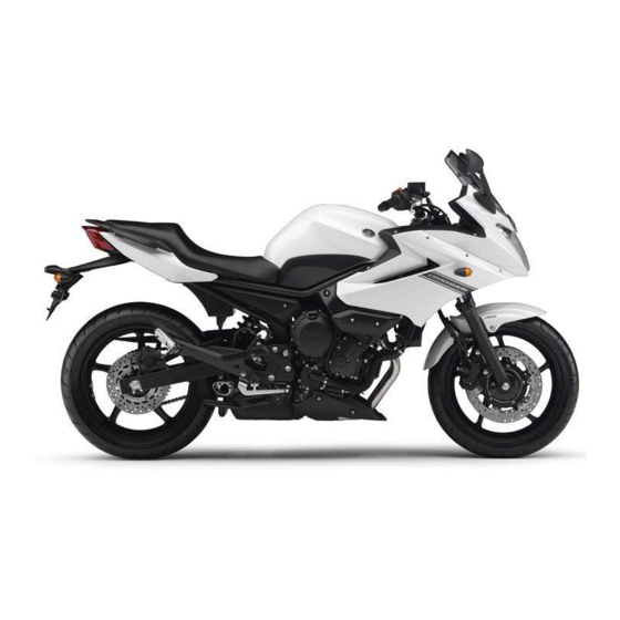
- Page 1 Read this manual carefully before operating this vehicle. OWNER’S MANUAL XJ6SA 36D-28199-E0...
- Page 2 Read this manual carefully before operating this vehicle. This manual should stay with this vehicle if it is sold. YAMAHA MOTOR ELECTRONICS CO., LTD. 1450-6, Mori, Mori-machi, Shuchi-gun, Shizuoka-ken, 437-0292 Japan DECLARATION of CONFORMITY Company: YAMAHA MOTOR ELECTRONICS CO., LTD. Address: 1450-6, Mori, Mori-Machi, Shuchi-gun, Shizuoka-Ken, 437-0292 Japan Hereby declare that the product: Kind of equipment: IMMOBILIZER...
- Page 3 Yamaha a reputation for dependability. Please take the time to read this manual thoroughly, so as to enjoy all advantages of your XJ6SA. The Owner’s Manual does not only instruct you in how to operate, inspect and maintain your motorcycle, but also in how to safeguard yourself and oth- ers from trouble and injury.
-
Page 4: Important Manual Information
IMPORTANT MANUAL INFORMATION EAU10133 Particularly important information is distinguished in this manual by the following notations: This is the safety alert symbol. It is used to alert you to potential personal injury hazards. Obey all safety messages that follow this symbol to avoid possible injury or death. - Page 5 IMPORTANT MANUAL INFORMATION EAU10200 XJ6SA OWNER’S MANUAL ©2012 by Yamaha Motor Co., Ltd. 1st edition, July 2012 All rights reserved. Any reprinting or unauthorized use without the written permission of Yamaha Motor Co., Ltd. is expressly prohibited. Printed in Japan.
-
Page 6: Table Of Contents
TABLE OF CONTENTS SAFETY INFORMATION ....1-1 Adjusting the shock absorber Adjusting the engine idling assembly ........3-20 speed ........6-19 DESCRIPTION ........2-1 Sidestand ........3-21 Checking the throttle grip free Left view ..........2-1 Ignition circuit cut-off system ..3-22 play ........... 6-20 Right view ........2-2 Valve clearance ...... - Page 7 TABLE OF CONTENTS Checking the front fork ....6-33 Checking the steering ....6-33 Checking the wheel bearings ..6-34 Battery ..........6-34 Replacing the fuses ......6-35 Replacing the headlight bulb ..6-37 Replacing the tail/brake light bulb ...........6-38 Replacing a turn signal light bulb ...........6-38 Replacing the license plate light bulb ...........6-39 Auxiliary light bulb ......6-40...
-
Page 8: Safety Information
SAFETY INFORMATION ● EAU1028A Never operate a motorcycle with- yourself conspicuous appears to out proper training or instruction. be very effective in reducing the Take a training course. Beginners chance of this type of accident. Be a Responsible Owner should receive training from a cer- Therefore: As the vehicle’s owner, you are respon- tified instructor. - Page 9 SAFETY INFORMATION ● Many accidents involve inexperi- • Always signal before turning or Protective Apparel enced operators. In fact, many op- changing lanes. Make sure that The majority of fatalities from motorcy- erators who have been involved in other motorists can see you. cle accidents are the result of head in- accidents do not even have a cur- ●...
- Page 10 SAFETY INFORMATION ● Avoid Carbon Monoxide Poisoning Do not run engine outdoors where When loading within this weight limit, All engine exhaust contains carbon engine exhaust can be drawn into keep the following in mind: monoxide, a deadly gas. Breathing car- a building through openings such ●...
- Page 11 Yamaha accessories, which are avail- formed to your vehicle that change any lightweight as possible and able only from a Yamaha dealer, have of the vehicle’s design or operation should be kept to a minimum. been designed, tested, and approved characteristics can put you and others •...
- Page 12 SAFETY INFORMATION ● tor and may limit control ability, Check that the fuel cock (if therefore, such accessories are equipped) is in the “OFF” position not recommended. and that there are no fuel leaks. ● Use caution when adding electri- ●...
-
Page 13: Description
DESCRIPTION EAU10410 Left view 1. Air filter element (page 6-18) 9. Engine oil filter cartridge (page 6-11) 2. Idle adjusting screw (page 6-19) 10.Engine oil drain bolt (page 6-11) 3. Seat lock (page 3-18) 4. Main fuse (page 6-35) 5. Fuse box (page 6-35) 6. -
Page 14: Right View
DESCRIPTION EAU10420 Right view 1. Helmet holder (page 3-18) 9. Brake pedal (page 3-14) 2. Battery (page 6-34) 10.Rear brake light switch (page 6-25) 3. Rear brake fluid reservoir (page 6-26) 11.Shock absorber assembly spring preload adjusting ring (page 3-20) 4. -
Page 15: Controls And Instruments
DESCRIPTION EAU10430 Controls and instruments 1. Clutch lever (page 3-13) 2. Left handlebar switches (page 3-11) 3. Main switch/steering lock (page 3-2) 4. Multi-function meter unit (page 3-8) 5. Front brake fluid reservoir (page 6-26) 6. Right handlebar switches (page 3-11) 7. -
Page 16: Instrument And Control Functions
● the vehicle along with all three keys to Do not expose any key to exces- a Yamaha dealer to have them re-reg- sively high temperatures. istered. Do not use the key with the red ● Do not place any key close to bow for driving. -
Page 17: Main Switch/Steering Lock
INSTRUMENT AND CONTROL FUNCTIONS ● Keep other immobilizer system EAU10472 EAU38530 Main switch/steering lock keys away from the main switch All electrical circuits are supplied with as they may cause signal inter- power; the meter lighting, taillight, li- ference. cense plate light and auxiliary light come on, and the engine can be start- ed. - Page 18 INSTRUMENT AND CONTROL FUNCTIONS EAU10684 To unlock the steering ECA11020 LOCK NOTICE The steering is locked, and all electrical Do not use the parking position for systems are off. The key can be re- an extended length of time, other- moved.
-
Page 19: Indicator Lights And Warning Lights
The oil level warning high beam of the headlight is switched light will flash ten times, then go off for 2.5 seconds. If this occurs, have a Yamaha dealer check the EAU11254 vehicle. Oil level warning light “ ”... - Page 20 INSTRUMENT AND CONTROL FUNCTIONS ECA10021 NOTICE Do not continue to operate the en- gine if it is overheating. ● For radiator-fan-equipped vehi- cles, the radiator fan(s) automati- cally switch on or off according to the coolant temperature in the ra- diator.
- Page 21 INSTRUMENT AND CONTROL FUNCTIONS Display Conditions What to do Under 39 °C Message “Lo” is displayed. OK. Go ahead with riding. (Under 103 °F) 40–116 °C Coolant temperature is dis- OK. Go ahead with riding. (104–242 °F) played. Stop the vehicle and allow it to idle until 117–134 °C Coolant temperature flashes.
- Page 22 The ABS may not work correctly. If any if a problem is detected in the electrical light can be checked by turning the key of the above occurs, have a Yamaha circuit monitoring the engine. If this oc- to “ON”. The indicator light should...
-
Page 23: Multi-Function Meter Unit
INSTRUMENT AND CONTROL FUNCTIONS EAU46765 multi-function meter unit Tachometer Multi-function meter unit equipped with the following: ● a speedometer ● a tachometer ● an odometer ● two tripmeters (which show the distance traveled since they were last set to zero) ●... -
Page 24: Fuel Meter
INSTRUMENT AND CONTROL FUNCTIONS Clock 5. Push the “RESET” button to set mode “F-TRIP” and start counting the the minutes. distance traveled from that point. In that 6. Push the “SELECT” button and case, push the “SELECT” button to then release it to start the clock. switch the display between the various tripmeter and odometer modes in the Odometer and tripmeter modes... - Page 25 ECA10021 times, then go off for approximately 3 NOTICE nosis device for various electrical cir- seconds. If this occurs, have a Yamaha cuits. Do not continue to operate the en- dealer check the electrical circuit. If a problem is detected in any of those gine if it is overheating.
-
Page 26: Handlebar Switches
If a problem is detected in the immobi- key and both standard keys to a EAU1234B Handlebar switches lizer system circuits, the immobilizer Yamaha dealer and have the stan- system indicator light will flash and the dard keys re-registered. Left display will indicate an error code. - Page 27 INSTRUMENT AND CONTROL FUNCTIONS Right position. To cancel the turn signal EAU12733 Hazard switch “ ” lights, push the switch in after it has re- With the key in the “ON” or “ ” posi- turned to the center position. tion, use this switch to turn on the haz- ard lights (simultaneous flashing of all EAU12500...
-
Page 28: Clutch Lever
INSTRUMENT AND CONTROL FUNCTIONS EAU12820 EAU12871 EAU26824 Clutch lever Shift pedal Brake lever The brake lever is located on the right side of the handlebar. To apply the front brake, pull the lever toward the throttle grip. 1. Clutch lever 1. -
Page 29: Brake Pedal
EAU51670 Brake pedal ● The ABS performs a self-diagno- The Yamaha ABS (Anti-lock Brake sis test each time the vehicle first System) features a dual electronic con- starts off after the key is turned to trol system, which acts on the front and “ON”... -
Page 30: Fuel Tank Cap
INSTRUMENT AND CONTROL FUNCTIONS wheel hubs may be damaged, result- EAU13074 Fuel tank cap ing in improper performance of the The fuel tank cap cannot be closed un- ABS system. less the key is in the lock. In addition, the key cannot be removed if the cap is not properly closed and locked. -
Page 31: Fuel
EWA15151 refueling, be sure to insert the WARNING Your Yamaha engine has been de- pump nozzle into the fuel tank filler Gasoline is poisonous and can signed to use regular unleaded gaso- hole. Stop filling when the fuel cause injury or death. -
Page 32: Fuel Tank Breather Hose And Overflow Hose
INSTRUMENT AND CONTROL FUNCTIONS EAU51190 EAU13433 ECA10701 Fuel tank breather hose and Catalytic converter NOTICE overflow hose This model is equipped with a catalytic Use only unleaded gasoline. The use converter in the exhaust system. of leaded gasoline will cause unre- EWA10862 pairable damage to the catalytic WARNING... -
Page 33: Seat
INSTRUMENT AND CONTROL FUNCTIONS EAU32980 EAU46751 Seat Helmet holder To remove the seat 1. Insert the key into the seat lock, and then turn it counterclockwise. 1. Projection 2. Seat holder 1. Helmet holder 2. Push the rear of the seat down to 2. -
Page 34: Storage Compartment
INSTRUMENT AND CONTROL FUNCTIONS ● EAU14453 Do not exceed the maximum Storage compartment load of 184 kg (406 lb) for the ve- hicle. 1. Helmet 2. Helmet holding cable 1. Storage compartment 3. Helmet holder The storage compartment is located 3. -
Page 35: Handlebar Position
This shock absorber assembly is erence. Have a Yamaha dealer adjust spaces. Fold the mirrors back to their equipped with a spring preload adjust- the position of the handlebar. -
Page 36: Sidestand
EWA10241 Spring preload setting: sembly yourself. Take the shock WARNING Minimum (soft): absorber assembly to a Yamaha The vehicle must not be ridden with dealer for any service. Standard: the sidestand down, or if the side- stand cannot be properly moved up... -
Page 37: Ignition Circuit Cut-Off System
INSTRUMENT AND CONTROL FUNCTIONS this system regularly and have a EAU44902 Ignition circuit cut-off system Yamaha dealer repair it if it does not The ignition circuit cut-off system (com- function properly. prising the sidestand switch, clutch switch and neutral switch) has the fol- lowing functions. - Page 38 ”. stand during this inspection. • 3. Turn the key on. If a malfunction is noted, have a Yamaha 4. Shift the transmission into the neutral position. dealer check the system before riding. 5. Push the start switch. Does the engine start? With the engine still running: The neutral switch may not be working correctly.
-
Page 39: For Your Safety - Pre-Operation Checks
• If necessary, add recommended coolant to specified level. 6-14 • Check cooling system for leakage. • Check operation. • If soft or spongy, have Yamaha dealer bleed hydraulic system. • Check brake pads for wear. Front brake • Replace if necessary. - Page 40 • Make sure that operation is smooth. • Check throttle grip free play. Throttle grip 6-20, 6-30 • If necessary, have Yamaha dealer adjust throttle grip free play and lubricate cable and grip housing. • Make sure that operation is smooth. Control cables 6-30 •...
- Page 41 • Tighten if necessary. Instruments, lights, signals • Check operation. — and switches • Correct if necessary. • Check operation of ignition circuit cut-off system. Sidestand switch 3-21 • If system is not working correctly, have Yamaha dealer check vehicle.
-
Page 42: Operation And Important Riding Points
● a lean angle sensor to stop the en- understand, ask your Yamaha dealer. ● The transmission is in the neutral gine in case of a turnover. In this EWA10271 position. -
Page 43: Shifting
The neutral indicator The gear positions are shown in the il- light should come on. If not, ask a lustration. Yamaha dealer to check the elec- trical circuit. To shift the transmission into the neu- 3. Start the engine by pushing the tral position, press the shift pedal down start switch. -
Page 44: Tips For Reducing Fuel Consumption
OPERATION AND IMPORTANT RIDING POINTS ECA10260 EAU16810 EAU16841 Tips for reducing fuel con- Engine break-in NOTICE sumption There is never a more important period ● Even with the transmission in in the life of your engine than the period Fuel consumption depends largely on the neutral position, do not between 0 and 1600 km (1000 mi). -
Page 45: Parking
Yamaha dealer check the vehi- touch them and be burned. cle. ● Do not park on a slope or on soft... -
Page 46: Periodic Maintenance And Adjustment
– possibly leading to pending on the weather, terrain, geo- that is certified (if applicable). Yamaha death. See page 1-3 for more in- graphical location, and individual use, dealers are trained and equipped to... -
Page 47: Owner's Tool Kit
If you do not have the tools or experi- ence required for a particular job, have a Yamaha dealer perform it for you. -
Page 48: Periodic Maintenance Chart For The Emission Control System
● From 50000 km (30000 mi), repeat the maintenance intervals starting from 10000 km (6000 mi). ● Items marked with an asterisk should be performed by a Yamaha dealer as they require special tools, data and technical skills. EAU46910 Periodic maintenance chart for the emission control system... -
Page 49: General Maintenance And Lubrication Chart
PERIODIC MAINTENANCE AND ADJUSTMENT EAU1770F General maintenance and lubrication chart ODOMETER READING ANNUAL ITEM CHECK OR MAINTENANCE JOB 1000 km 10000 km 20000 km 30000 km 40000 km CHECK (600 mi) (6000 mi) (12000 mi) (18000 mi) (24000 mi) √ Air filter element •... - Page 50 PERIODIC MAINTENANCE AND ADJUSTMENT ODOMETER READING ANNUAL ITEM CHECK OR MAINTENANCE JOB 1000 km 10000 km 20000 km 30000 km 40000 km CHECK (600 mi) (6000 mi) (12000 mi) (18000 mi) (24000 mi) • Check operation and for exces- √ √...
- Page 51 PERIODIC MAINTENANCE AND ADJUSTMENT ODOMETER READING ANNUAL ITEM CHECK OR MAINTENANCE JOB 1000 km 10000 km 20000 km 30000 km 40000 km CHECK (600 mi) (6000 mi) (12000 mi) (18000 mi) (24000 mi) • Check operation and for oil leak- √...
- Page 52 PERIODIC MAINTENANCE AND ADJUSTMENT EAU18680 ● Air filter • This model’s air filter is equipped with a disposable oil-coated paper element, which must not be cleaned with com- pressed air to avoid damaging it. • The air filter element needs to be replaced more frequently when riding in unusually wet or dusty areas. ●...
-
Page 53: Removing And Installing Cowlings And Panels
PERIODIC MAINTENANCE AND ADJUSTMENT EAU18712 EAU46770 Removing and installing cowl- Panel A ings and panels To remove the panel The cowlings and panels shown need Remove the bolt and the quick fasten- to be removed to perform some of the er, and then take the panel off. - Page 54 PERIODIC MAINTENANCE AND ADJUSTMENT To install a panel Place the panel in the original position, and then install the bolts. 1. Panel B 1. Cowling A 2. Bolt 2. Bolt 2. Push the panel outwards to un- To install the cowling hook the projection underneath EAU46740 Place the cowling in the original posi-...
-
Page 55: Checking The Spark Plugs
Do not attempt to diagnose such problems yourself. Instead, have a Yamaha dealer check the vehicle. If a spark plug shows signs of electrode erosion and excessive carbon or other 1. Turn signal light lead connector deposits, it should be replaced. -
Page 56: Engine Oil And Oil Filter Cartridge
PERIODIC MAINTENANCE AND ADJUSTMENT Before installing a spark plug, the spark EAU47551 Engine oil and oil filter car- plug gap should be measured with a If a torque wrench is not available when tridge wire thickness gauge and, if necessary, installing a spark plug, a good estimate The engine oil level should be checked adjusted to specification. - Page 57 PERIODIC MAINTENANCE AND ADJUSTMENT 6. Insert and tighten the engine oil dipstick, and then install and tight- en the oil filler cap. To change the engine oil (with or without oil filter cartridge replace- ment) 1. Remove cowling A. (See page 6-8.) 2.
- Page 58 PERIODIC MAINTENANCE AND ADJUSTMENT Recommended engine oil: See page 8-1. An oil filter wrench is available at a Oil quantity: Yamaha dealer. Without oil filter cartridge replace- ment: 6. Apply a thin coat of clean engine 2.50 L (2.64 US qt, 2.20 Imp.qt)
-
Page 59: Coolant
Yamaha dealer check ● from the guide, and then remove Make sure that the vehicle is posi- the vehicle. - Page 60 EAU47573 To change the coolant water has been added to the 1. Place the vehicle on the center- coolant, have a Yamaha dealer stand. check the antifreeze content of 2. Remove cowlings A and C. (See the coolant as soon as possible, page 6-8.)
- Page 61 PERIODIC MAINTENANCE AND ADJUSTMENT 5. Remove the coolant reservoir 9. After the coolant is completely breather hose from the guide, and drained, thoroughly flush the cool- then remove the coolant reservoir ing system with clean tap water. cap. 10. Install the coolant drain bolt and its new gasket, and then tighten the bolt to the specified torque.
- Page 62 If 14. Install the coolant reservoir cap. ervoir. If necessary, remove the coolant is leaking, have a Yamaha 15. Start the engine, let it idle for sev- coolant reservoir cap, add coolant dealer check the cooling system.
-
Page 63: Replacing The Air Filter Element
1. Fuel tank bolt are not pinched. If any hose is 1. Air filter element 4. Remove the air filter case cover by damaged, have a Yamaha dealer 2. Air intake manifold removing the screws. NOTICE: replace the hose before starting... -
Page 64: Adjusting The Engine Idling Speed
If the specified idling speed cannot be follows at the intervals specified in the obtained as described above, have a periodic maintenance and lubrication Yamaha dealer make the adjustment. chart. The engine should be warm before making this adjustment. Check the engine idling speed and, if necessary, adjust it to specification by turning the idle adjusting screw. -
Page 65: Checking The Throttle Grip Free Play
Therefore, it must be adjusted by a Yamaha dealer is essential to maintain the tires in good at the intervals specified in the periodic condition at all times and replace them maintenance and lubrication chart. - Page 66 225 kPa (2.25 kgf/cm², 33 psi) glass fragments in it, or if the sidewall is surface must first be “broken Rear: cracked, have a Yamaha dealer re- in” for it to develop its optimal 250 kPa (2.50 kgf/cm², 36 psi) place the tire immediately.
- Page 67 WARNING ed below have been approved for this Tires age, even if they have not been model by Yamaha Motor Co., Ltd. This motorcycle is fitted with super- used or have only been used occasion- high-speed tires. Note the following ally.
-
Page 68: Cast Wheels
● Always adjust the tire air pres- er damage before each ride. If any sure according to the operating damage is found, have a Yamaha conditions. dealer replace the wheel. Do not attempt even the smallest repair to the wheel. A deformed or cracked 1. -
Page 69: Checking The Brake Lever Free Play
There should be no free play at the adjusting nut in direction (a). To brake lever end. If there is free play, decrease the clutch lever free play, have a Yamaha dealer inspect the turn the adjusting nut in direction brake system. (b). -
Page 70: Brake Light Switches
The front and rear brake pads must be come on just before braking takes ef- checked for wear at the intervals spec- fect. If necessary, have a Yamaha deal- ified in the periodic maintenance and er adjust the brake light switches. -
Page 71: Checking The Brake Fluid Level
EAU43112 Rear brake Checking the brake fluid level peared, have a Yamaha dealer replace Before riding, check that the brake fluid the brake pads as a set. is above the minimum level mark. Check the brake fluid level with the top... -
Page 72: Changing The Brake Fluid
Changing the brake fluid moving. Use only DOT 4 brake check the brake pads for wear and the Have a Yamaha dealer change the fluid from a sealed container. brake system for leakage. If the brake brake fluid at the intervals specified in ●... -
Page 73: Drive Chain Slack
EAU22760 EAU53950 Drive chain slack To adjust the drive chain slack Consult a Yamaha dealer before ad- Using the alignment marks on each The drive chain slack should be justing the drive chain slack. drive chain puller, make sure that both checked before each ride and adjusted 1. -
Page 74: Cleaning And Lubricating The Drive Chain
PERIODIC MAINTENANCE AND ADJUSTMENT EAU23025 may contain substances that Cleaning and lubricating the could damage O-rings. drive chain [ECA11111] The drive chain must be cleaned and lubricated at the intervals specified in the periodic maintenance and lubrica- tion chart, otherwise it will quickly wear out, especially when riding in dusty or wet areas. -
Page 75: Checking And Lubricating The Cables
Yamaha dealer at the intervals speci- bricated if necessary. ed if necessary. If a cable is damaged fied in the periodic maintenance chart. -
Page 76: Checking And Lubricating The Brake And Clutch Levers
PERIODIC MAINTENANCE AND ADJUSTMENT EAU23143 Recommended lubricant: Recommended lubricants: Checking and lubricating the Lithium-soap-based grease Brake lever: brake and clutch levers Silicone grease The operation of the brake and clutch Clutch lever: Lithium-soap-based grease levers should be checked before each ride, and the lever pivots should be lu- bricated if necessary. -
Page 77: Checking And Lubricating The Centerstand And Sidestand
The operation of the centerstand and The swingarm pivots must be lubricat- sidestand should be checked before ed by a Yamaha dealer at the intervals each ride, and the pivots and metal-to- specified in the periodic maintenance metal contact surfaces should be lubri- and lubrication chart. -
Page 78: Checking The Front Fork
2. Hold the lower ends of the front fork does not operate smoothly, tion. WARNING! To avoid injury, fork legs and try to move them for- have a Yamaha dealer check or re- securely support the vehicle so ward and backward. If any free pair it. -
Page 79: Checking The Wheel Bearings
WARNING To charge the battery ● Electrolyte is poisonous and Have a Yamaha dealer charge the bat- dangerous since it contains sul- tery as soon as possible if it seems to furic acid, which causes severe have discharged. Keep in mind that the burns. -
Page 80: Replacing The Fuses
PERIODIC MAINTENANCE AND ADJUSTMENT battery tends to discharge more quickly is turned to “OFF”, then con- EAU47172 Replacing the fuses if the vehicle is equipped with optional nect the positive lead before The main fuse and the fuse boxes, electrical accessories. connecting the negative lead. - Page 81 PERIODIC MAINTENANCE AND ADJUSTMENT avoid causing extensive dam- 4. If the fuse immediately blows age to the electrical system and again, have a Yamaha dealer possibly a fire. check the electrical system. [EWA15131] Specified fuses: Main fuse: 30.0 A Headlight fuse: 20.0 A...
-
Page 82: Replacing The Headlight Bulb
● Headlight lens 6. Install the cowling. Do not affix any type of tinted 7. Have a Yamaha dealer adjust the film or stickers to the headlight headlight beam if necessary. lens. Do not use a headlight bulb of a wattage higher than specified. -
Page 83: Replacing The Tail/Brake Light Bulb
PERIODIC MAINTENANCE AND ADJUSTMENT EAU47021 EAU24204 Replacing the tail/brake light Replacing a turn signal light bulb bulb 1. Remove the seat. (See page 1. Remove the turn signal light lens 3-18.) by removing the screw. 2. Remove the tail/brake light bulb socket (together with the bulb) by turning it counterclockwise. -
Page 84: Replacing The License Plate Light Bulb
PERIODIC MAINTENANCE AND ADJUSTMENT EAU24313 Replacing the license plate light bulb 1. Remove the license plate light unit by removing the screws. 1. Turn signal light bulb 1. License plate light bulb socket 2. License plate light bulb 3. Insert a new bulb into the socket, 3. -
Page 85: Auxiliary Light Bulb
1. Auxiliary light bulb self. However, should your motorcycle If the auxiliary light does not come on, require any repair, take it to a Yamaha have a Yamaha dealer check the elec- dealer, whose skilled technicians have trical circuit or replace the bulb. -
Page 86: Troubleshooting Charts
Remove the spark plugs and check the electrodes. The engine does not start. Have a Yamaha dealer check the vehicle. Check the compression. 4. Compression The engine does not start. There is compression. - Page 87 Start the engine. If the engine overheats again, have a The coolant level Yamaha dealer check and repair the cooling system. is OK. If coolant is not available, tap water can be temporarily used instead, provided that it is changed to the recommended coolant as soon as possible.
-
Page 88: Motorcycle Care And Storage
Some models are equipped with ble. Rust and corrosion can develop matte colored finished parts. Be Cleaning sure to consult a Yamaha dealer for even if high-quality components are ECA10772 advice on what products to use be- used. A rusty exhaust pipe may go un-... - Page 89 For additional clean- during winter are extremely corrosive in ● For motorcycles equipped with ing, use Yamaha Windshield Cleaner combination with water, carry out the or another high-quality windshield a windshield: Do not use strong following steps after each ride in the cleaner.
- Page 90 EWA11131 WARNING which does not affect your visibility and ● Consult a Yamaha dealer for ad- which cannot be easily recognized. Contaminants on the brakes or tires vice on what products to use. can cause loss of control.
-
Page 91: Storage
MOTORCYCLE CARE AND STORAGE EAU26182 2. Fill up the fuel tank and add fuel e. Remove the spark plug caps Storage stabilizer (if available) to prevent from the spark plugs, and then the fuel tank from rusting and the install the spark plugs and the Short-term fuel from deteriorating. - Page 92 MOTORCYCLE CARE AND STORAGE Make any necessary repairs before storing the motorcycle.
-
Page 93: Specifications
SPECIFICATIONS Dimensions: Engine oil: Fuel: Overall length: Recommended brand: Recommended fuel: 2120 mm (83.5 in) YAMALUBE Regular unleaded gasoline only Overall width: Type: Fuel tank capacity: 770 mm (30.3 in) SAE 10W-30, 10W-40, 10W-50, 15W-40, 17.3 L (4.57 US gal, 3.81 Imp.gal) Overall height: 20W-40 or 20W-50 Fuel reserve amount:... - Page 94 SPECIFICATIONS 2nd: Manufacturer/model: Rim size: 1.947 (37/19) DUNLOP/ROADSMART 17M/C x MT4.50 3rd: Loading: Front brake: 1.556 (28/18) Maximum load: Type: 4th: 184 kg (406 lb) Dual disc brake 1.333 (32/24) (Total weight of rider, passenger, cargo and Operation: 5th: accessories) Right hand operation 1.190 (25/21) Tire air pressure (measured on cold...
- Page 95 SPECIFICATIONS Charging system: Coolant temperature warning light: AC magneto Battery: Engine trouble warning light: Model: ABS warning light: GT12B-4 Voltage, capacity: Immobilizer system indicator light: 12 V, 10.0 Ah Headlight: Fuses: Bulb type: Main fuse: Halogen bulb Bulb voltage, wattage × quantity: 30.0 A Headlight fuse: Headlight:...
-
Page 96: Consumer Information
Record the vehicle identification num- ber and model label information in the spaces provided below for assistance when ordering spare parts from a Yamaha dealer or for reference in case the vehicle is stolen. VEHICLE IDENTIFICATION NUMBER: 1. Vehicle identification number 1. - Page 97 INDEX Maintenance, emission control system ... 6-3 Matte color, caution ........ 7-1 ABS ............3-14 Engine break-in ........5-3 Model label ..........9-1 ABS warning light ........3-7 Engine idling speed.......6-19 Multi-function meter unit ......3-8 Air filter element, replacing ....6-18 Engine oil and oil filter cartridge ....6-11 Auxiliary light bulb.........
- Page 98 INDEX Tires ............6-20 Tool kit ............ 6-2 Troubleshooting ........6-40 Troubleshooting charts ......6-41 Turn signal indicator light ......3-4 Turn signal light bulb, replacing .... 6-38 Turn signal switch ......... 3-12 Valve clearance ........6-20 Vehicle identification number ....9-1 Wheel bearings, checking.....
- Page 100 PRINTED ON RECYCLED PAPER PRINTED IN JAPAN 2012.08-0.3×1 CR...