Table of Contents
Advertisement
USER'S MANUAL
Of
Intel Q67 Express Chipset
Based
M/B for LGA 1155 Quad Core Ready
Intel Core Processor
J29FAN - Q67
Rev: 1.0
,
Release date: July
2011
Trademark:
* Specifications and Information contained in this documentation are furnished for information use only, and are
subject to change at any time without notice, and should not be construed as a commitment by manufacturer.
Advertisement
Table of Contents

Related Manuals for Intel Q67


Summary of Contents for Intel Q67
- Page 1 USER'S MANUAL Intel Q67 Express Chipset Based M/B for LGA 1155 Quad Core Ready Intel Core Processor J29FAN - Q67 Rev: 1.0 , Release date: July 2011 Trademark: * Specifications and Information contained in this documentation are furnished for information use only, and are...
-
Page 2: Table Of Contents
TABLE OF CONTENT ENVIRONMENTAL SAFETY INSTRUCTION................iii ENVIRONMENTAL PROTECTION ANNOUCEMENT.............. iii USER’S NOTICE ........................iv MANUAL REVISION INFORMATION ..................iv ITEM CHECKLIST ........................iv CHAPTER 1 INTRODUCTION OF THE MOTHERBOARD SPECIFICATION ......................1 LAYOUT DIAGRAM....................2 CHAPTER 2 HARDWARE INSTALLATION JUMPER SETTING ..................... -
Page 3: Environmental Safety Instruction
Environmental Safety Instruction Avoid the dusty, humidity and temperature extremes. Do not place the product in any area where it may become wet. 0 to 40 centigrade is the suitable temperature. (The figure comes from the request of the main chipset) Generally speaking, dramatic changes in temperature may lead to contact malfunction and crackles due to constant thermal expansion and contraction from the welding spots’... -
Page 4: User's Notice
USER’S NOTICE COPYRIGHT OF THIS MANUAL BELONGS TO THE MANUFACTURER. NO PART OF THIS MANUAL, INCLUDING THE PRODUCTS AND SOFTWARE DESCRIBED IN IT MAY BE REPRODUCED, TRANSMITTED OR TRANSLATED INTO ANY LANGUAGE IN ANY FORM OR BY ANY MEANS WITHOUT WRITTEN PERMISSION OF THE MANUFACTURER. -
Page 5: Specification
Support four serial ATA2 ports Serial ATAⅠ /Ⅱ / Support two serial ATA3 ports Ⅲ Integrated Intel 82574L and 82579LM Gigabit Ethernet Dual LAN Chip LAN chip that supports Fast Ethernet LAN function of providing 10Mb/100Mb/1000Mb Ethernet data transfer rate... -
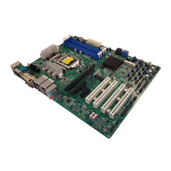
Page 6: Layout Diagram
ATX Power VGA Port Connector RJ-45 Over USB Ports RJ-45 Over USB Ports CPU Socket LGA1155 6-CH Audio Connector PCI Ex16 Slot Intel Q67 Chipset SATA1_2 Connectors PCIE x 4 Slots MINI PCIE SATA3_4 Connectors Slot PCIE x1 Slot MSATA... - Page 7 Motherboard Jumper Position JP10 JBAT JP20 JP12 JP14 COPEN JP17 JP16 JP18 JP19 JP13 JP15 JP11 Jumper Jumper Name Description JBAT CMOS RAM Clear Function Setting 3-pin Block USB Port Power On Function Setting 3-pin Block USB Port Power On Function Setting 3-pin Block COM2 Header Pin9 Function Selecting 6-pin Block...
- Page 8 JP17 COM2 Header Pin9 Function Selecting 6-pin Block JP18 COM2 Header Pin9 Function Selecting 6-pin Block JP19 COM2 Header Pin9 Function Selecting 6-pin Block JP20 Mini PCI-E Power VCC3.3V/3.3V SB 3-pin Block Connectors Connector Name Description KB/MS from UK1 PS2 Keyboard/Mouse Connector 6-pin Female VGA1 Video Graphic Attach Connector...
-
Page 9: Chapter 2 Hardware Installation
Chapter 2 Hardware Installation 2-1 Jumper Setting (1) Clear CMOS (3-pin): JBAT JBAT 1-2 Short: Normal 2-3 Short: Clear CMOS CMOS Clear Setting (2) JP3 (3-pin): USB Power On Function Setting 1-2 closed : USB POWER-ON Disabled(default) 2-3 closed: USB POWER-ON Enabled (3) JP5 (3-pin): USB Power On Function Setting 1-2 closed : USB POWER-ON Disabled(default) - Page 10 (4) JP8 (6-pin): COM2 Header Pin9 Function Selecting 1-2 closed: RS232 3-4 closed : +12V 5-6 closed : +5V (5) JP9 (6-pin): COM2 Port RS232/485/422 Function Select 1-2 closed: RS232 3-4 closed : RS485 5-6 closed : RS422 (6)JP10 (6-pin): KB/MS/USB Power-On Function Setting JP10 1-2 closed : KB/MS/USB POWER-ON Disabled(default) JP10...
- Page 11 (7) JP11 (6-pin): COM2 Pin9 function select JP11 1-2 closed: RS232 3-4 closed : +12V 5-6 closed : +5V (8) JP12 (6-pin): COM3 Pin9 function select JP12 1-2 closed: RS232 3-4 closed : +12V 5-6 closed : +5V (9) JP13 (6-pin): COM4 Pin9 function select JP13 1-2 closed: RS232 3-4 closed : +12V...
- Page 12 JP14 1-2 closed: RS232 3-4 closed : +12V 5-6 closed : +5V (11) JP15 (6-pin): COM6 Pin9 function select JP15 1-2 closed: RS232 3-4 closed : +12V 5-6 closed : +5V (12) JP16 (6-pin): COM7 Pin9 function select JP16 1-2 closed: RS232 3-4 closed : +12V 5-6 closed : +5V (13) JP17 (6-pin): COM9 Pin9 function select...
- Page 13 JP17 1-2 closed: RS232 3-4 closed : +12V 5-6 closed : +5V (14)JP18 (6-pin): COM10 Pin9 function select JP18 1-2 closed: RS232 3-4 closed : +12V 5-6 closed : +5V (15)JP19 (6-pin): COM8 Pin9 function select JP19 1-2 closed: RS232 3-4 closed : +12V 5-6 closed : +5V...
- Page 14 (16)JP20 (3-pin): Mini PCI-E Power VCC 3.3V/3.3 VSB Function Select JP20 1-2 closed : MINI PCI-E 2-3 closed : MINI PCI-E VCC= 3.3V VCC= 3.3VSB (17) CASE_ OPEN (2-pin): Case Open Message Display function select CASE_OPEN 1-2 Open: Normal 1-2 Short: Case Open Case Open Display Function Pin 1-2 shorted: Case open display function enabled.
-
Page 15: Connectors And Headers
Connectors and Headers 2-2-1 Rear I/O Back Panel Connectors DVI Port RJ-45 LAN Port Serial Port Line-IN/ PS/2 KB/MS Port Optical SPDIF OUT Line-OUT MIC-IN USB Ports VGA Port USB Ports HDMI Port (1) PS/2 Keyboard Connector: UK1 The connectors are for PS/2 keyboard (Purple) and PS/2 Mouse (Green). (2) D-Sub 15-pin Connector: VGA1 VGA connector is the 15-pin D-subminiature female connector;... -
Page 16: Motherboard Internal Connectors
2-2-2 Motherboard Internal Connectors Power Connector (24-pin block): ATXPWR ATX Power Supply connector: This is a new defined 24-pins connector that usually comes with ATX case. The ATX Power Supply allows using soft power on momentary switch that connect from the front panel switch to 2-pins Power On jumper pole on the motherboard. - Page 17 (2) ATX 12V Power Connector (8-pin block): ATX12V This is a new defined 8-pin connector that usually comes with ATX Power Supply. The ATX Power Supply which fully supports AMD AM3 processor must including this connector for support extra 12V voltage to maintain system power consumption.
-
Page 18: Header Pin Definition
2-2-3 Header Pin Definition (1) Line-Out/MIC Header for Front Panel (9-pin): FP_AUDIO This header is connected to Front Panel Line-out, MIC connector with cable. Pin 1 Line-Out, MIC Headers (2) CD AUDIO-In Headers (4-pin): CDIN CDIN are the connectors for CD-Audio Input signal. Please connect it to CD-ROM CD-Audio output connector. - Page 19 SPEAK1 Pin 1 Pin 1 PWRLED1 (5) Front Panel Header: JW-FP JW FP Pin 1 (6) USB Port Headers (4-pin): USB1/USB2/USB3 USB1 Pin 1...
- Page 20 (7) FAN Power Headers: SYSFAN1 (3-pin); SYSFAN2 (4-pin); CPUFAN (4-pin) CPUFAN SYSFAN2 Control SYSFAN1 +12V Clock FAN Headers (8) GPIO Header (10-pin): GPIO_CON Pin 1 GPIO_CON Header (9) Serial Port Header (9-Pin): COM2/3/4/5/6/7/8/9/10 Pin6 Pin5 Pin1 Serial COM Port 9-pin Block...
- Page 21 (10) RS232/422/485 Header (4-pin): TX-RXCOM1 TX-RXCOM1 Pin 1 TX-RX Header (11) HDMI-SPDIF Out header (2-pin): HDMI_SPDIF HDMI_SPDIF_OUT HDMI_SPDIF Header (12) TPM Header (19-pin):TPM Pin 1 TPM Header...
-
Page 22: Chapter 3 Introducing Bios
Chapter 3 Introducing BIOS Notice! The BIOS options in this manual are for reference only. Different configurations may lead to difference in BIOS screen and BIOS screens in manuals are usually the first BIOS version when the board is released and may be different from your purchased motherboard. Users are welcome to download the latest BIOS version form our official website. -
Page 23: Bios Menu Screen
BIOS Menu Screen The following diagram show a general BIOS menu screen: Menu Bar General Help Items Current Setting Value Menu Items Function Keys BIOS Menu Screen Function Key In the above BIOS Setup main menu of, you can see several options. We will explain these options step by step in the following pages of this chapter, but let us first see a short description of the function keys you may use here: Press←→... -
Page 24: Getting Help
Getting Help Main Menu The on-line description of the highlighted setup function is displayed at the top right corner the screen. Status Page Setup Menu/Option Page Setup Menu Press F1 to pop up a small help window that describes the appropriate keys to use and the possible selections for the highlighted item. -
Page 25: Main Menu
Main Menu Main menu screen includes some basic system information. Highlight the item and then use the <+> or <-> and numerical keyboard keys to select the value you want in each item. System Date Set the date. Please use TAB to switch between data elements. System Time Set the time. -
Page 26: Advanced Menu
3-7 Advanced Menu... - Page 27 Launch LAN1/LAN2 PXE OpROM Use this item to enable or disable boot option for legacy network devices. Launch Storage OpROM Use this item to enable or disable boot option for legacy mass storage devices with option ROM. ERP Function Use this item to enable or disable ERP function for this board. ►...
- Page 28 Use this item to turn on/off the MLC (L2) streamer prefetcher. Adjacent Cache Line Prefetch Use this item to turn on/off prefetching of adjacent cache lines. Intel Virtualization Technology The optional settings: [Enabled]; [Disabled]. When set as [Enabled], a VHM can utilize the additional hareware capabilities provided by Vanderpool Technology.
- Page 29 The optional settings are: [Disabled]; [Enhanced]; [Compatible]. Serial-ATA Controller 1 The optional settings are: [Disabled]; [Enhanced]. ► Intel IGD SWSCI OpRegion IGD-Boot Type Use this item to select the video device which will be activated during POST. This has no effect if external graphics present.
- Page 30 ► COM2 Port Configuration Serial Port Use this item to enable or disable serial port (COM). Change Settings Use this item to select an optimal setting for super IO device. Serial Port Mode Select Use this item to set serial port as RS232 or RS422/485. CIR Controller Use this item to enable or disable CIR controller.
- Page 31 ► Voltage Configuration CPU Vcore 7-Shift Use this item to adjust CPU voltage by 7 step value. AXG Voltage Use this item to adjust AGX voltage by 7 step value. CPU VTT Use this item to adjust CPU VTT voltage by 7 step value. ►...
-
Page 32: Chipset Menu
3-8 Chipset Menu ► North Bridge LOW MMIO Align The optional settings are: [64M]; [1024M]. VT-d Use this item to enable or disable VT-d Initiate Graphics Adapter Select which graphics controller to use as the primary boot device. The optional settings are: [IGD]; [PCI/IGD]; [PCI/PEG]; [PEG/IGD]; [PEG/PCI]. IGD Memory Use this item to select IGO Share Memory Size The optional settings are: [Disable]/[32m]/[64m]/[128m]/[256m]/[512m]. - Page 33 ► South Bridge Wake on Lan from S5 Use this item to enable or disable GbE control PME in S5. Onboard Lan1 Device Use this item to enable or disable the PCI Express Ports in the Chipset. Restore AC Power Loss Use this item to specify what state to go to when power is re-applied after a power failure (G3 State).
-
Page 34: Boot Menu
3-9 Boot Menu Setup Prompt Timeout Use this item to set number of seconds to wait for setup activation key. Bootup Numlock State Use this item to select keyboard numlock state. The optional settings are: [On]; [Off]. Quite Boot Use this item to enable or disable Quite Boot option. Gate A20 Active The optional settings are: [Upon Request];... -
Page 35: Security Menu
3-10 Security Menu Security menu allow users to change administrator password and user password settings. -
Page 36: Save & Exit Menu
3-11 Save & Exit Menu Save & Exit menu allows user to load optimal defaults, save or discard your changes to BIOS items.
Need help?
Do you have a question about the Q67 and is the answer not in the manual?
Questions and answers