Myson KICKSPACE 500 Installation & Operation Manual
Kickspace
Hide thumbs
Also See for KICKSPACE 500:
- Installation & operating manual (12 pages) ,
- Manual (10 pages) ,
- Installation maintenance and operating instructions (8 pages)

Related Manuals for Myson KICKSPACE 500


Summary of Contents for Myson KICKSPACE 500
- Page 1 Installation, Operating, Maintenance and After Sales Manual. KICKSPACE ® 500, 600, 600-12V & 800 heatingthroughinnovation. Product Serial Number: Please leave this manual with the end user. Part Number: 1370054 Issue 4...
-
Page 2: Table Of Contents
Contents General Information Heating System Design Selection and Sizing for Heating Location Preparation Electrical Connection Water Connection ® Fitting the KICKSPACE Technical Data 10.0 Operating Instructions 11.0 Troubleshooting 12.0 Maintenance... -
Page 3: General Information
® The KICKSPACE 500, 600 & 800 MUST NOT be installed in a bathroom or other similar high humidity area. 2.0 Heating System Design This fan convector must be fitted on a two pipe, pumped 3. The system water must be above 43°C for fan to switch on, circulation heating system. -
Page 4: Electrical Connection
Fig. 1b Plinth opening - plinth mounting 6.0 Electrical Connection ® WARNING: KICKSPACE 500, 600 and 800 models must be earthed. l The electrical installation must comply with local or national l Remote Control Switch - A remote control switch is available wiring regulations. -
Page 5: Water Connection
® KICKSPACE 500, 600, 600-12V & 800 7.0 Water Connection Pipework must be positioned correctly to ensure flexible hoses are not kinked when installed. See Fig. 3. Only use the hose sets supplied with this unit. Do not use old or alternative hose sets. -
Page 6: Fitting The Kickspace
® KICKSPACE 500, 600, 600-12V & 800 ® 8.0 Fitting the KICKSPACE l Position the KICKSPACE l Replace the plinth and bring the KICKSPACE ® ® under the cupboard in the required forward into location, with the front edge just behind the line of the plinth. -
Page 7: Technical Data
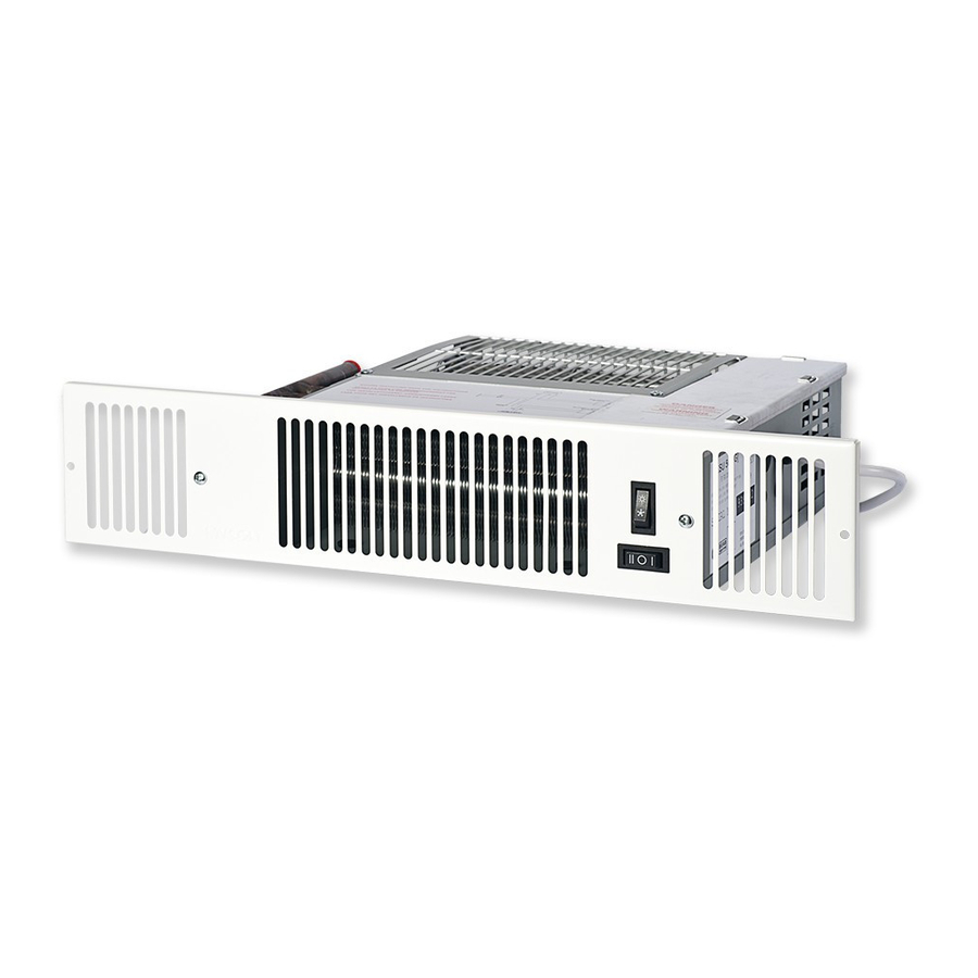
® KICKSPACE 500, 600, 600-12V & 800 ® 8.0 Fitting the KICKSPACE (continued...) l Complete the electrical installation, switch on and test the ® KICKSPACE Summer/Winter switch Switch for fan Boost Normal Fig. 8 9.0 Technical Data Dimensions ® ®... - Page 8 0.30 600-12V 26.4 32.7 600-12V 0.30 28.5 49.8 0.18 Noise levels tested in accordance with EN 23741. *Includes transformer. MOTOR Fan Selector Switch Chassis Summer/Winter Earth Switch LOW LIMIT THERMOSTAT ® Fig. 10 KICKSPACE 500, 600 & 800 wiring diagram...
-
Page 9: Operating Instructions
® KICKSPACE 500, 600, 600-12V & 800 9.0 Technical Data (continued...) Transformer MOTOR Mains Supply 240V Fan Selector Switch Connector Block Summer/Winter Switch LOW LIMIT THERMOSTAT ® Fig. 11 KICKSPACE 600-12V wiring diagram 10.0 Operating Instructions This unit is controlled by the switches on the front of the unit, or The fan speed can be set to boost by switching the fan speed by means of the wall mounted remote switching kit if fitted. -
Page 10: Troubleshooting
If the fan convector is still faulty after checking the above, call your installer or MYSON Service. Common Installation Faults heat, and the heating system must be correctly designed to provide adequate flow of hot water to the unit (see Section 2). -
Page 11: Maintenance
® KICKSPACE 500, 600, 600-12V & 800 12.0 Maintenance Before undertaking any maintenance activity isolate the This should involve internal cleaning of the heat exchanger using electrical supply. a soft brush or vacuum cleaner, taking care not to damage fan or heat exchanger. - Page 12 0845 402 3434, 0191 491 7568, sales@myson.co.uk, www.myson.co.uk heatingthroughinnovation. After Sales Service: MYSON Service, Somerden Road, Hull, East Yorkshire HU9 5PE T: 01482 713927, F: 01482 789056, service.convectors@myson.co.uk Spare parts and technical help on all Convector products are available from MYSON Service.
Need help?
Do you have a question about the KICKSPACE 500 and is the answer not in the manual?
Questions and answers