Table of Contents
Advertisement
Advertisement
Table of Contents

Related Manuals for DigiDesign C24


Summary of Contents for DigiDesign C24
- Page 1 C|24 ™ Version 7.4...
- Page 2 WARNING: This product contains chemicals, including lead, known to the State of California to cause cancer and birth This guide is copyrighted ©2008 by Digidesign, a division of defects or other reproductive harm. Wash hands after Avid Technology, Inc. (hereafter “Digidesign”), with all rights handling.
- Page 3 UL Standards: UL60065 7th /IEC 60065 7th 12) Unplug this apparatus during lightning storms or when and Canadian CAN/CSA C22.2 60065:03. Digidesign Inc., has unused for long periods of time. been authorized to apply the appropriate UL & CUL mark on its compliant equipment.
-
Page 5: Table Of Contents
About www.digidesign.com ........ - Page 6 Chapter 5. Connecting Your Studio ......... . 27 Connection Examples for Stereo Monitoring .
- Page 7 Chapter 9. Working with C|24 ..........89 Working with Sessions and Tracks .
- Page 8 viii C|24 Guide...
-
Page 9: Part I Introduction
Part I: Introduction... -
Page 11: Chapter 1: Welcome To C|24
Chapter 1: Welcome to C|24 Welcome to C|24™, Digidesign’s 24-channel Analog Audio Features control surface for Pro Tools®. • 16 microphone/line/DI preamplifiers with the following features: C|24 gives you hands-on access to nearly all of • Continuously variable input gain control the recording, routing, editing, and mixing features of Pro Tools. -
Page 12: System Requirements
C|24 may cause the unit to tested and approved. malfunction and may void your warranty. For a list of Digidesign-qualified computers, op- erating systems, and third-party devices, visit Water and Moisture the Digidesign website (www.digidesign.com). -
Page 13: Mechanical Specifications
Mechanical Specifications 12.5 in 17.3 in (31.8 cm) (43.9 cm) 2.56 in (6.5 cm) 3.86 in 25.6 in (9.8 cm) (65.1 cm) C|24 side dimensions 0.79 in (2 cm) 0.45 in 7.3 in (1.16 cm) (18.5 cm) 39.4 in (100 cm) C|24 back dimensions Chapter 1: Welcome to C|24... - Page 14 29.8 in (75.7 cm) 40.9 in (104 cm) C|24 top dimensions C|24 Guide...
-
Page 15: Connection Requirements
(not included) is highly recommended. Audio Cables for C|24 Monitoring Ethernet Connections Digidesign offers a range of DigiSnake cabling options for connecting Digidesign interfaces C|24 communicates with Pro Tools using and external sources to the C|24. Ethernet. -
Page 16: About This Guide
News and Events Get the latest news from User Tips are helpful hints for getting the Digidesign; sign up for a Pro Tools demo. most from your system. To learn more about these and other resources available from Digidesign, visit the Digidesign Important Notices include information that website (www.digidesign.com). -
Page 17: Chapter 2. C|24 Overview
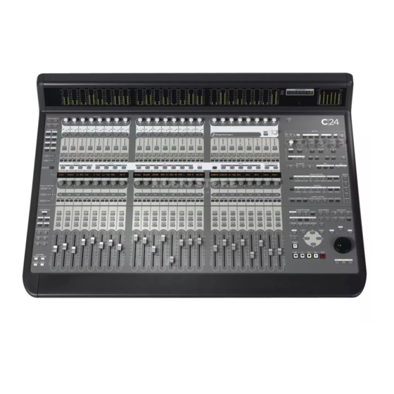
Chapter 2: C|24 Overview C|24 Top Panel Mic/Line/DI Preamplifier controls Line Submixer Meter Bridge Auto Enable Monitor switches section Channel Bar LCD displays Miscellaneous Rotary Encoders controls Auto Write To switches Transport and Auto Mode Navigation switches controls Modifier switches Fader section Figure 1. - Page 18 1/4-inch inputs connectors that override viewing, assigning, and editing Inputs, Outputs, the DB-25 inputs. Inserts, Sends, Pan controls, plug-in parameters, Digidesign PRE settings, and C|24 settings. Line Submixer LCD Displays C|24 also includes an analog line submixer with 8 stereo inputs and a stereo output that can be...
-
Page 19: C|24 Back Panel
C|24 Back Panel Preamps 9-16 section Submixer section Preamps 1-8 section Listen Mic Footswitch Power Supply connector connector connectors Monitor section Ethernet Ext Talk Mic connector connector Figure 2. C|24 back panel Submixer Section Listen Mic and External Talkback Mic Connectors Two DB-25 female connectors allow connection of a total of 16 channels (8 stereo inputs). - Page 20 C|24 Guide...
-
Page 21: Part Ii Installation
Part II: Installation... -
Page 23: Chapter 3. Installing And Configuring
Chapter 3: Installing and Configuring C|24 Installing C|24 Connecting C|24 to the Computer C|24 can be set on a level table top or mounted in a console or desk. C|24 communicates with Pro Tools using Ethernet. This connection uses a standard RJ45 Wherever you install C|24, make sure not to connector. -
Page 24: Starting Up And Shutting Down A Pro Tools System
If you have more than one Ethernet device in Shut down your system in this order: addition to C|24: Turn off monitor amplifiers or self-powered Connect one end of a standard Ethernet cable speakers. (not included) to the Ethernet port on the back Turn off all Pro Tools audio interfaces. - Page 25 Establishing Communication Naming C|24 Between C|24 and Pro Tools You can set a name for a C|24 unit so that it can Communication between C|24 and Pro Tools is be easily identified on a network shared with other Ethernet controllers. You can name C|24 configured by declaring the unit in Pro Tools.
-
Page 26: Setting C|24 Preferences
You can use a MIDI-based control surface Mic Pre Clip Hold Time (such as a Digidesign Command|8) or another MIDI-based controller (such as the Digidesign You can set the Clip Hold time for the C|24 Surround Panner Option) at the same time as a built-in mic/line/DI preamplifiers. -
Page 27: Chapter 4. Audio Connections
Chapter 4: Audio Connections C|24 offers versatile analog audio features for Mic/Line/DI Preamplifiers routing audio to and from Pro Tools and other audio equipment in your studio. C|24 provides 16 Mic/Line/DI preamplifiers that can be used to route input signals to a Pro Tools The Mic/Line/DI preamplifiers, built-in Line audio interface for recording. - Page 28 Alternate 1/4-inch connectors C|24 input chan- Line In 1-8 nels 1, 2, 9, and 10 also have alternate 1/4-inch Channel Signal balanced TRS connectors on the back panel, la- beled as follows: Line In 1 • DI 1 Line In 2 •...
- Page 29 Line Outputs Line In 9-16 Channel Signal Line Out 1-8 Channel Signal Line In 9 Line Out 1 Line In 10 Line Out 2 Line In 11 Line Out 3 Line In 12 Line Out 4 Line In 13 Line Out 5 Line In 14 Line Out 6 Line In 15...
-
Page 30: Line Submixer
Submix In 5-8 Line Submixer Channel Signal C|24 provides an 8x2 Line Submixer that can be Submixer Input 5 (Left) used to mix instrument inputs, auxiliary re- turns, or other external sources to stereo. Submixer Input 5 (Right) The output of the Line Submixer can then be Submixer Input 6 (Left) connected to Pro Tools audio interface inputs Submixer Input 6 (Right) -
Page 31: Monitor Section
Pro Tools In (PT 1-6 + Cue 1-2) Monitor Section Main Inputs Connect the outputs from your The C|24 Monitor section is a six-channel con- Pro Tools system to the Main Inputs. trol room monitoring system that allows con- Cue Inputs Connect cue outputs from your nection of up to four input sources (two 6-chan- Pro Tools system (such as a Send-based cue mix nel or 4-channel surround, and two stereo), two... - Page 32 Ext Stereo In (Ext St 1 + St 2) Control Room Out (5.1 Mon Out L:1 R:3) External Stereo Inputs Connect external stereo Main Outputs Connect the Main Outputs to sources (such as a DAT or CD player) to the Ex- your primary studio monitors (tables are shown ternal Stereo Inputs.
- Page 33 Main Outputs (LCRS) and Alternate Outputs Cue Outputs (Cue + SLS +TB) Cue Outputs Connect the Cue Outputs to the in- Control Room Out (5.1 Mon Out) puts of your cue system. Channel Signal Studio LS Outputs Connect Studio LS Outputs to Main Output Left (L) speakers in your live room.
- Page 34 Listen and Talkback Microphones C|24 provides connectors for a Listen micro- phone and an optional External Talkback micro- phone. Listen Mic This XLR connector lets you connect a microphone to provide two-way communica- tion between the studio and the control room. External Talkback Mic This XLR connector lets you connect an external microphone to use in place of the built-in Talkback microphone.
-
Page 35: Chapter 5. Connecting Your Studio
Chapter 5: Connecting Your Studio Connection Examples for Stereo Monitoring You can set up a basic stereo monitoring system using 2-channel input from Pro Tools. This in- put can be monitored on channels 1 (Left) and 3 (Right) of the C|24 Main Monitor outputs, or in the C|24 Alt Monitor (Stereo) outputs. - Page 36 Monitoring System Inputs Monitoring System Outputs Main Inputs and Cue Inputs Main Outputs (Stereo) and Alternate Outputs Pro Tools In (PT 1-6 + Cue 1-2) Control Room Out (5.1 Mon Out L:1 R:3) Chan Signal Chan Signal Main Input Left (L) from Pro Tools Out 1 Main Output Left (L) to Main speaker L no connection no connection...
-
Page 37: Stereo Studio Connections
Stereo Studio Connections (Example Setup) Rack Pro Tools Preamp Line Out Stereo Out 1-2 to Pro Tools Cue Out 1-2 CD player or DAT deck Submixer Ext Stereo In Line Submixer In Mic In Line In C|24 Pro Tools In Monitor Alt Out Cue Out Headphone Out... -
Page 38: Connection Examples For Surround Monitoring
Connection Examples for Surround Monitoring You can set up a surround monitoring system using up to 6-channel input from Pro Tools. 5.1, LCRS, or Stereo input can be monitored in the C|24 Main Monitor outputs. Stereo input can also be monitored in the C|24 Alt Monitor (Stereo) outputs. - Page 39 Monitoring System Inputs Monitoring System Outputs Monitor Inputs and Cue Inputs Main Outputs (5.1) and Alternate Outputs Pro Tools In (PT 1-6 + Cue 1-2) Control Room Out (5.1 Mon Out L:1 R:3) Chan Signal Chan Signal Main Output Left (L) to Left speaker Main Input Left (L) from Pro Tools Out 1 Main Output Center (C) to Center speaker Main Input Center (C) from Pro Tools Out 2...
-
Page 40: 5.1 Surround Studio Connections
5.1 Surround Studio Connections (Example Setup) 192 I/O Pro Tools Preamp Line Out Ch 1-6 Out to Pro Tools Cue Out 1-2 CD player or DAT deck Ext Talkback & Listen Mics Ext Stereo In Line Submixer In Mic In Line In C|24 Pro Tools In... - Page 41 Chapter 5: Connecting Your Studio...
- Page 42 C|24 Guide...
-
Page 43: Part Iii Reference
Part III: Reference... -
Page 45: Chapter 6. C|24 Pro Tools Controls
Chapter 6: C|24 Pro Tools Controls Fader Fader Section Each channel has a touch-sensitive motorized fader for controlling channel volume in Normal Channel Strip mode and a wide range of parameters in Flip mode. When you are automating a parameter Automation on a fader in Touch mode, touching the fader Mode... - Page 46 When MIDI controls are displayed on the chan- (Pan/Send view or Insert Select view). If your nel fader and encoder, the Input Monitor switch system includes a Digidesign PRE, most mic pre flashes. controls can be accessed in Channel View.
- Page 47 Pre/Post Switch • Mic Pre view: If your system includes a Digidesign PRE, controlling mic pre set- The Pre/Post switch is available only when C|24 tings is in Sends Console view. • Groups view: Selecting Group IDs for new...
- Page 48 LED Displays Mem Loc/Win Cfg Mode Shows the track name on the top row and available Memory Locations or Window Configurations on the bottom row. Display Mode switch Sends Console View LED displays In Sends Console view, the Display Mode switch cycles through the following Send display LED displays and Display Mode switch modes:...
- Page 49 When you press a lit Insert switch, C|24 enters When you double-press a Send switch, C|24 en- Insert Select view, and displays the channel’s in- ters Expanded Pan view, and displays the pan serts across the LCD displays. From Insert Select controls for a track.
-
Page 50: Global Automation Switches
EQ and Dynamics Bypass Switch See “Working with Automation” on page 103. The EQ and Dynamics Bypass switch changes The Automation Mode switch lets you cycle the the function of the EQ and Dynamics switches channel through Touch, Latch, Touch/Latch, on all channels, putting them in Bypass mode. - Page 51 The Automation Mode switches mirror the When writing is enabled for an automation type function of the on-screen Automation Mode se- but it is not currently writing on any track in the lector for each track, and let you change auto- session, the corresponding switch lights solid.
-
Page 52: Modifier Switches
Automation Write To Switches Modifier Switches (Pro Tools HD Only) Shift (add) Option/Alt (all) Automation switch switch Write To All switch Control/Win Command/Ctrl Automation Automation switch switch Write To End Write to Start switch switch Modifier switches Automation Automation Write to Next Write to Punch switch The Modifier keys duplicate the function of the... -
Page 53: Channel Bar
Channel Bar The Channel Bar spans the center of the Fader section of C|24, and includes controls for inserts, chan- nel assignments, pan display, send display, and Soft Key functions. Inserts Assign Soft Keys Sends Channel Bar section section section switch section Scroll... - Page 54 Assign Section Pan Section When in Pan Console view or Pan/Send Chan- nel view, the switches in the Pan section deter- mine which pan controls are assigned to the channel encoders. The corresponding pan, di- vergence, or percentage values are shown in the Escape/ Input LCD displays.
- Page 55 The following console preferences, actions and Center Percentage Switch and automation preferences are available: The Center Percentage (%) switch assigns the Center Percentage parameter to the encoder. Console Preferences LFE Switch Faders (Faders On/Off) Temporarily turns off C|24 faders to prevent fader movement when The LFE switch assigns LFE volume control to monitoring a mix.
- Page 56 ChanWn (Channel Window Display) Determines Automation Preferences whether displaying plug-in or send parameters (Pro Tools HD Only) opens the corresponding plug-in or send win- dow on-screen in Pro Tools. AutoJn (Auto Join) Sets tracks in Latch mode to automatically resume writing of automation af- When this preference is set to “Yes,”...
-
Page 57: Miscellaneous Controls
Sends Section Miscellaneous Controls The Sends section switches are used in Console view to focus sends in the LCD displays. Send Edit Mode Switches volume is controlled by the encoders. Spot Grid Sends switch switch switches (A-E/F-J) switch Shuffle Slip Sends section of the Channel Bar switch switch... - Page 58 The Mic Pre switch toggles C|24 into Mic Pre When the Alternate Function switch is on, the view, which shows the controls of any con- bottom function is active for all switches in this nected Digidesign PRE. section. See “Mic Pre View” on page 82. Edit Tools Trim Selects the Trim tool and cycles through the versions of the tool.
- Page 59 Grabber Selects the Grabber tool and cycles Tab to Transients through the versions of the tool. The Tab to Transients switch toggles the Tab to Pencil Selects the Pencil tool and cycles through Transients option. The switch lights when the the versions of the tool.
-
Page 60: Global Controls
Plug-in Opens and closes the window for the cur- Global Controls rently focused plug-in. Pan Opens and closes the window for the cur- rently focused pan controls. Transport The Transport switch opens and closes Do To the Transport window, and lets you show/hide Solo Clear Vel Sens Master Rec... - Page 61 Solo Clear Switch Groups The Solo Clear switch clears all latched Solo switches in the session. This switch flashes when any channel is soloed. Create Groups switch Plug-in Safe Switch Enable Groups switch The Plug-In Safe switch enables plug-in automa- Modify Groups switch tion safe mode for the currently focused plug-in.
-
Page 62: Transport And Navigation Controls
Pre-Roll Switch Plays audio starting at the pre- Transport and Navigation roll point up to the beginning of the selection. Controls Mark In Switch Plays audio starting at the selec- tion start through the length of the post-roll Transport Mode Switches amount. - Page 63 In Audition mode, the Pre-Roll and Post-Roll Zoom Preset Switches switches activate playback of various parts of an edit selection. See “Audition Switch” on page 54. Zoom Preset 2 Zoom Preset 1 Mark In and Mark Out Switches Zoom Preset 3 Zoom Preset 4 In Audition mode, the Mark In and Mark Out switches activate playback of various parts of an...
- Page 64 Utility mode lets you view C|24 system informa- Zoom Switch tion, run diagnostic tests, and set certain C|24 The Zoom switch puts the Arrow switches in preferences. For complete information, see Zoom mode. Appendix B, “Utility Mode.” Navigate Switch Enter Switch The Navigate switch puts the Arrow switches in The Enter switch is used to confirm operations, Navigate mode.
- Page 65 Scrub/Shuttle Controls Bank/Nudge Switches Trim switch Shuttle Scrub switch switch Scrub/ Shuttle wheel Bank Left Bank Right switch switch Nudge switch Scrub/Shuttle controls Bank/Nudge switches Scrub/Shuttle Wheel Bank Switches The Scrub/Shuttle wheel is used for cursor loca- The Bank switches move the display of tracks on tion, scrubbing, zooming, window navigation, C|24 to the left or to the right 24 channels at a and banking faders.
- Page 66 Transport Switches Masters Switch Masters switch Play Fast Forward switch switch Rewind Stop Record switch switch switch Masters switch Transport switches The Masters switch cycles temporary display of The C|24 Transport switches correspond to the Master Fader tracks and VCA Master tracks buttons in the Pro Tools Transport window.
-
Page 67: Meter Bridge
Talkback Switch Meter Bridge Meters and Counter Display Main Counter Output Meters Talkback switch Talkback switch The Talkback switch activates the Talkback mi- crophone. The Talkback switch lights to indi- cate that Talkback is active. Talkback signal is summed with the Cue inputs and also sent to the Slate output. - Page 68 Time Display Format Indicators The left side of the C|24 meter bridge has 24 pairs of 14-segment LED bar graphs for display- The indicator to the left of the Main Counter ing track levels. These meters can display pre- or shows the currently displayed time scale format.
-
Page 69: Chapter 7. C|24 Analog Audio Controls
Chapter 7: C|24 Analog Audio Controls Monitor Section The Monitor section includes controls for 6-channel control room monitoring, 2-channel studio loudspeaker and cue system routing, headphone output, and listenback and talkback input. Output Mode switch Output Mode Solo Control Room Main Output Preset Indicators switch switches... - Page 70 Output Mode switch Output Mode Solo Control Room Main Output Preset Indicators switch switches C|24 Monitor section (top) Output Mode Switch and Indicators Control Room Main Output Switches C|24 has three preset monitor modes available The Control Room Main Output switches en- for the Control Room Main Outputs: able the corresponding output channels.
- Page 71 Control Room Headphone Studio LS Listen Mic Talkback encoder level knob level knob level knob level knob level knob Alt Monitor From Cue Studio LS Main>Cue Listen Mic switch switch switch switch switch C|24 Monitor section (middle) Control Room Encoder and LEDs Studio LS Level Knob and Switch The Control Room encoder controls the output The Studio LS level knob controls volume to the...
- Page 72 Main Stereo 1 switch switch switch switch Stereo 2 Mute Mono Alt Sur switch switch switch switch C|24 Monitor section (bottom) Master Control Room Output Control Room Input Selectors Controls Control Room Input selections are mutually ex- clusive (X-OR) unless the Sum switch is en- Mute Switch gaged, when they are additive.
- Page 73 Sum Switch Submixer Output The Sum switch causes Control Room Inputs to When the To Monitor switch in the Line Sub- be additive instead of mutually exclusive mixer controls is engaged, the stereo output (X-OR). When active, the Sum switch tempo- from the Submixer is routed internally and au- rarily bypasses any Trim values currently ap- tomatically summed with the Left and Right...
- Page 74 Control Room Alt Outputs Control Room Output Dim Function The Control Room Alt Outputs can be trimmed The Dim switch applies an adjustable gain re- relative to the Main Output to compensate for duction to all Control Room monitor outputs. differences between speaker systems.
-
Page 75: Mic/Line/Di Preamplifier Controls
Mic/Line/DI Preamplifier Controls The Mic/Line/DI Preamplifier section includes 16 sets of controls for the built-in microphone pream- plifiers, and switches to apply phantom power (in two groups of 8 channels). Mic/Line/DI preamplifiers Mic/Line/DI preamplifiers 9-16 MIc/Line/DI preamplifiers Mic Pre Controls Source/HPF Switch The Source/HPF switch cycles through input sources and toggles high-pass filter in/out status... -
Page 76: Line Submixer Controls
Line Submixer Controls The Line Submixer section includes an input level control for each of its 8 inputs and a master output level control that sets the output levels to the external stereo output or the internal feed to the Mon- itor section. -
Page 77: Part Iv Applications
Part IV: Applications... -
Page 79: Chapter 8. Operating Views And Modes
C|24 offers additional views for working with Stereo Output Path The track’s encoder controls Digidesign PRE settings, Pro Tools Mix/Edit panning in the stereo field with the L(C)R pan Groups, Window Configurations and Memory parameter. - Page 80 To display pan controls across the console: Sends Console View Press the Home switch to put C|24 in Pan In Sends Console view, each rotary encoder con- Console view. trols Send volume for a given Send position on the track. Press a Pan parameter switch in the Pan sec- tion of the Channel Bar.
-
Page 81: Channel Views
When the send is post-fader, the switch is un- Muting Sends in Sends Console View lit and the LCD display temporarily shows “Post.” To toggle the mute status of a track’s send: In the Channel Bar, press the Sends switch To exit Send Console view: that corresponds to the name of Send position you want to mute. - Page 82 For each assigned Send on the track, the LCD Muting Sends in Pan/Send Channel display shows Send position, Send path, “Snd- View Pan” on the top row, and Send mute state, “more” and Send pre/post state on the bottom To toggle the mute state of a send on a track: row.
- Page 83 Setting the Pre-/Post-Fader Status of Expanded Pan View Sends in Pan/Send Channel View You can display all the Pan controls for a track in Expanded Pan view. To toggle the pre-/post-fader state of any of the sends on a track: To display the Pan controls for a track in Expanded Press the Send switch in the track’s channel Pan view:...
- Page 84 To adjust a track’s volume in Expanded Pan view: To toggle track panner linking in Expanded Pan view: Press the Send switch in the track’s channel Press the Send switch in the track’s channel strip. strip. Press the encoder switch that corresponds to Press the encoder switch that corresponds to “Main Pan.”...
- Page 85 For the Send you want to display, press the en- To adjust a Send’s pan controls in Expanded Send view: coder switch that corresponds to “more.” Press the Send switch in the track’s channel The LCD displays show the track name in the strip.
- Page 86 To link a Send’s Pan controls to the Main Pan Insert Select View controls of a track (“Follows Main Pan”): In Insert Select view, insert controls on the fo- Press the Send switch in the track’s channel cused channel are displayed horizontally across strip.
- Page 87 To focus a plug-in: To open multiple plug-in windows: Press the Insert switch in the track’s channel Hold the Shift (add) Modifier switch while strip. opening each new plug-in window. Press the encoder switch to the left of the To close all open plug-in windows: “more”...
- Page 88 To toggle the bypass state of all plug-ins at the In Parameter view, the LCD displays show the same insert positions on all tracks: parameter names in the top row and the param- eter values in the bottom row. The encoders and Press the Insert/Send Bypass switch so that it is the encoder switches control the corresponding lit.
- Page 89 To toggle the automation safe status of the To toggle the bypass state of all Dyn or EQ plug-ins currently focused plug-in: at the same insert positions on all tracks: Press the Safe switch in the Inserts Section of Press the Dyn/EQ Bypass switch so that it is lit. the Channel Bar.
-
Page 90: Mic Pre View
To target controls for a specific channel on a multi- Mic Pre View mono plug-in: From the multi-mono plug-in setup page, If you have a Digidesign PRE in your system, Mic press the encoder switch that corresponds to Pre views let you control the PRE from C|24. “Target.”... -
Page 91: Groups View
In Expanded Mic Pre view, the following con- Creating Groups trols are shown in the LCD displays: To create a group: • Gain: controlled by the encoder • Source: chosen with the encoder Select the tracks you want to include in the group. -
Page 92: Window Configuration View
Modifying Groups To suspend all groups: Press the Suspend switch in the Groups sec- To modify a group: tion. The Suspend Groups switch follows latch- ing behavior, and flashes to indicate groups are Press the Modify switch in the Groups section. suspended. -
Page 93: Memory Location View
To edit a Window Configuration: To recall a Memory Location: In Window Configuration view, hold the In Memory Location view, press the encoder Ctrl/Win modifier switch and press the encoder switch that corresponds to the location name in switch that corresponds to the Window Config- the LCD display. -
Page 94: Fader Display Modes
Home/Pan Flip Mode Fader Display Modes When C|24 is in Pan Console or “Home” view, Flip mode transfers control assignments as fol- Normal Mode lows: In Normal mode, Pro Tools tracks are displayed • Faders control channel pan. on C|24 in a standard console format. In this •... -
Page 95: Assign Mode
Expanded Pan/Expanded Send View Assign Mode • Faders control Send parameters. You can assign Inputs, Outputs, Inserts, or Sends • Rotary encoders are disabled. from C|24 using Assign mode. • Encoder switches toggle/cycle through stepped parameters. When in Assign mode, an arrow (“>”) appears to the left of pathnames or plug-in names in the Plug-in Flip Mode LCD displays to indicate the current assign-... - Page 96 C|24 Guide...
-
Page 97: Chapter 9: Working With C|24
Chapter 9: Working with C|24 This chapter covers representative Pro Tools Creating New Tracks tasks that can be accomplished with C|24. For When you are creating new tracks in Pro Tools, complete information on C|24 controls for you can navigate the New Tracks dialog using Pro Tools, see Chapter 6, “C|24 Pro Tools Con- the Arrow switches on C}24. - Page 98 Naming Tracks or Adding Track Resetting Controls to Their Comments Default Values When you are naming tracks or adding track To reset a channel’s track volume to 0 dB: comments, you can open and navigate the Press Default + the channel Select switch. Name Track dialog from C|24.
-
Page 99: Assigning Pro Tools Paths
Applying Actions to Multiple Assigning Pro Tools Paths Tracks You can assign track inputs, outputs, sends, and To apply actions to multiple tracks: inserts from C|24. Do one of the following: • Press the Do To All or the Do To Selected Assigning Inputs and Outputs switch to apply the action to one control. - Page 100 Assigning Sends To assign a Send from Channel view: Press the Send switch in the track’s channel To assign a Send from Console view: strip. The Send positions for the track are shown in the LCD displays. Press a Send switch in the Sends section of the Channel Bar.
- Page 101 Assigning Inserts To remove an insert: While in Insert Select view, hold Default and To assign an Insert: press the encoder switch under the Insert. Press the Insert switch in the track’s channel strip. The Insert positions for the track are Making Single Assignments shown in the LCD displays.
-
Page 102: Working With Pro Tools Windows
To show/hide the MIDI and Counter sections of Working with Pro Tools the Transport window: Windows Hold the Opt/Alt (all) Modifier switch and press the Transport switch. Entering Numerical Values in To show/hide the Pre/Post-Roll section of the Pro Tools Windows Transport window: You can enter numerical values in the on-screen Hold the Command/Ctrl+Ctrl/Win Modifier... - Page 103 To open/close Output windows for multiple Displaying Plug-In Windows tracks: To focus a plug-in on C|24 and open its window: Press the Home switch to put C|24 in Pan Console view. Press the Insert switch of the track whose plug- in you want to focus.
-
Page 104: Recording
Recording Audio Recording To record audio: You can select certain record modes, record en- able or record safe tracks for recording, arm the Record-enable the tracks where you want to Pro Tools Transport, and initiate recording from record by pressing their Record Enable switches. C|24. - Page 105 When you are finished, press the Stop switch QuickPunch Recording in the Transport section. To punch in/out while audio recording with QuickPunch: Loop Recording MIDI Press the QuickPunch switch in the Transport Modes section so that it is lit. To loop record MIDI: Press the Link Edit and Timeline switch in the To hear track material up to the start of the punch, enable pre-roll by pressing the Pre-Roll...
-
Page 106: Navigating And Selecting In The Edit Window
To zoom out so that all regions are visible in the Navigating and Selecting in Edit window: the Edit Window Double-press the Zoom switch. Zooming in the Edit Window Using Zoom Presets To zoom in horizontally on all tracks: To store a Zoom Preset: Press the Zoom switch. - Page 107 To vertically scroll the contents of the Edit window To scrub while adding to the end of a selection: or Mix window: Hold the Ctrl/Win+Shift (add)+Opt/Alt (all) Focus the window you want to scroll by click- Modifier switches while scrubbing the end of ing in it or by pressing the corresponding win- the selection.
- Page 108 Scrubbing Audio in the Edit Scrubbing while Trimming a Region or Selection Window (Pro Tools HD Only) To scrub audio in Scrub mode: While Pro Tools is stopped, press the Scrub To use Trim/Scrub mode: switch. Navigate to a region or selection you want to trim.
-
Page 109: Editing
Auditioning Start and End Points Editing of Selections In Audition mode, you can listen to either the Selecting Edit Tools start or end of a selection, with or without pre- roll or post-roll. You can select Edit tools by pressing the corre- sponding switches in the Tools &... -
Page 110: Controlling Track Display On C|24
To copy the current plug-in settings: To cascade the position of tracks on C|24 one channel at a time: Focus the plug-in whose settings you want to Hold any of the Nudge/Bank switches and copy. (For information on focusing plug-ins, see turn the Scrub/Shuttle wheel clockwise or coun- “Focusing Plug-Ins on C|24”... -
Page 111: Mixing
Setting the Automation Mode of Mixing Channels To cycle a channel forward through the Displaying Master Faders and VCA automation modes: Masters Press the Automation Mode switch on the You can temporarily focus the Master Faders or channel. VCA Master tracks (VCA Master tracks are avail- able in Pro Tools HD only) in your session in the To cycle a channel backward through the right side of the C|24 faders. - Page 112 To set the automation mode of all channels: To toggle the automation bypass status of a plug-in: Press the Do To All switch. Press the Insert switch in the track’s channel Press an Automation Mode switch or switches strip. (Write, Touch, Latch, Touch+Latch, Trim, Read, For the plug-in you want to display, press the or Off).
- Page 113 Previewing Automation Capturing Automation (Pro Tools HD Only) (Pro Tools HD Only) To preview a new automation value for a control: To capture automation values: Enable the track for automation by cycling its Enable the tracks whose automation values Automation Mode switch to enable Touch, you want to capture by cycling their Automa- Latch, or Touch/Latch mode.
- Page 114 Joining Automation Values Writing Automation to the Start End, or All of a Track or Selection (Pro Tools HD Only) (Pro Tools HD Only) To Join automation values: To manually write the current automation values Make sure the controls you want to join are in to the start, end, or all of a track or selection: a write-enabled state.
-
Page 115: Appendix A. C|24 Connector Pinouts
Appendix A: C|24 Connector Pinouts Mic Preamp Inputs 1–8 Female DB-25 Connectors Channel Hot (+) Cold (–) Ground (shield) All C|24 DB-25 connector pinouts conform to 5 Preamp the pin numbering scheme shown below. Mic In 5 6 Preamp Mic In 6 7 Preamp Mic In 7 8 Preamp... - Page 116 Line Out 1–8 Mic Preamp Inputs 9–16 Channel Hot (+) Cold (–) Ground (shield) Preamp Line Outputs 1–8 5 Preamp Channel Hot (+) Cold (–) Ground (shield) Mic In 13 1 Preamp 6 Preamp Line Out 1 Mic In 14 2 Preamp 7 Preamp Line Out 2...
- Page 117 Line Out 9–16 Submixer 1–8 ST Preamp Line Outputs 9–16 Submix In 1–4 (ST) Channel Hot (+) Cold (–) Ground (shield) Submixer Stereo Inputs 1–4 1 Preamp Channel Hot (+) Cold (–) Ground (shield) Line Out 9 2 Preamp Submixer Line Out In 1 Left 3 Preamp...
- Page 118 Submix In 5–8 (ST) Monitor Section Submixer Stereo Inputs 5–8 Pro Tools In Channel Hot (+) Cold (–) Ground (shield) Pt 1–6 + Cue 1–2 Pro Tools and Cue Inputs Submixer In 5 Left Channel Hot (+) Cold (–) Ground (shield) 1 Main In Submixer Left...
- Page 119 Surround In Ext Stereo In Alt Sur 1–6 Ext St 1 + St 2 Alternate Surround Inputs (1–6) External Stereo Inputs 1 and 2 Channel Hot (+) Cold (–) Ground (shield) Ground Channel Hot (+) Cold (–) (shield) 1 Alt Surround 1 Stereo In In Left...
-
Page 120: Xlr And Trs Connectors
Control Room Out Cue Outputs 5.1 Mon Out L:1 R:3 Cues + SLS + TB Main and Alternate Outputs Cue and Studio LS Monitor Outputs Ground Ground Channel Hot (+) Cold (–) Channel Hot (+) Cold (–) (shield) (shield) 1 Main Out Left 1 Cue Out Left 2 Main Out... -
Page 121: Appendix B. Utility Mode
Appendix B: Utility Mode C|24 Utility mode lets you run diagnostic tests, Tests set hardware preferences, view system informa- tion, and reset system settings. The C|24 Test pages let you test the mechanical and electronic components of the unit. Entering and Exiting Utility To display the Test pages: Mode Press the Utility switch. - Page 122 Internal To exit the External Ethernet test: Press the encoder switch that corresponds to The Internal test verifies the first stage of Ether- “Exit.” net communication by sending data packets through the unit’s Ethernet link chip. LED Test Page To perform the Internal Ethernet test: The LED tests let you test all red, yellow, or From the Ethernet Test page, press the en- green LEDs on C|24 individually.
- Page 123 Display Test Page Group Faders can be moved to test group re- sponse. Fader position values are shown in the The Display tests let you test the LCD displays LCD displays (0-1023). This test shows which and the Main Counter on C|24. faders are currently being touched by displaying the letter “T”...
-
Page 124: Preferences
Switch Test Page To enable the external Talkback microphone: Press the Utility switch. The Switch test lets you test each switch on C|24 individually. Press the encoder switch that corresponds to “Preferences.” To test any switch: Press the encoder switch that corresponds to From the Switch Test page, press the switch “Talkback.”... - Page 125 Mic Pre Clip Hold For each Footswitch (A and B), press the en- coder switch that corresponds to any of the You can set the Clip Hold time for the C|24 following: built-in mic/line/DI preamplifiers. • Play: Starts and stops the Pro Tools Trans- port.
-
Page 126: System
• Unit Name (as named on the Unit Name coder under “Character.” page) To move forward and backward in the text • Unit Number: Digidesign serial number for field, turn the encoder under “Position.” the unit When you are finished, press the encoder •... - Page 127 To set the C|24 name to the default: Resetting Analog Signal Routing Press the Utility switch. This page lets you reset C|24 monitor and cue source selections, and Monitor solo, phantom Press the encoder switch that corresponds to power, Mic/Line and HPF settings to their de- “System.”...
-
Page 128: Auto Talkback
Resetting Monitor Gain Settings Auto Talkback This page lets you reset gain and trim levels in Auto Talkback is a setting that automatically the C|24 monitor section (set with the Control turns on the Talkback and Listen microphones Room rotary encoder) to their default values. when the Pro Tools Transport is stopped, and turns the Talkback and Listen microphones off To reset monitor gain levels and trim offsets:... -
Page 129: Index
index Symbols punching 104 Safe mode 45 +48V (phantom power) 67 setting modes 103 suspending 43 Numerics Write controls 106 5.1 output mode (Monitor section) 62 Automation Enable switches 43 Mute 43 Pan 43 Plug-in 43 Actions (Soft Keys) 48 Send Level 43 AFL/PFL 65 Send Mute 43... - Page 130 Main input 64 Main Output switches 62 C|24 unit Main outputs 24, 65 declaring 17 Mono function 64, 66 dimensions 5 Mute 64 naming 17 output controls 63, 64 Center Percentage switch 47 Output Mode controls 62 Channel Bar 10, 45 resetting 119, 120 Channel Select switches 38 Solo mode 62...
- Page 131 Edit Tool switches 50 Grabber 51 Global Controls Pencil 51 Default 52 Select 50 Do To All 52 Smart 51 Do To Selected 52 Trim 50 Input Monitor 53 Edit window 94 Master Record Enable 53 Enable switch (Groups) 53 Plug-in Safe 53 Solo Clear 53 encoder switch functions 39...
- Page 132 Merge-Record 51 Wait For Note 51 L(C)R switch 46 MIDI Operations switch (Window switches) 52 L/R switch 47 MIDI Real-Time Properties 52 Latch switch (automation) 43 Mix switch (Window switches) 51 LCRS output mode (Monitor section) 62 modifier switches 44 LFE switch 47 Command/Ctrl 44 line preamplifiers 67...
- Page 133 Plug-in switch (automation) 43 Plug-in switch (Window switches) 52, 95 Safe switch 45 plug-ins Save switch 56, 89 bypassing 79 saving sessions 89 closing 95 Scroll switches (Channel Bar) 49 focusing 78 Scrub switch 57, 100 opening 79, 95 Scrub/Shuttle controls Post-Roll switch 54, 101 Scrub switch 57 Pre Fader Listen mode 65...
- Page 134 Studio LS level controls 63 Transport switches 58 Studio LS outputs 25 Transport window 94 submixer 10, 68 Trim switch (automation) 43 Sum switch 65 Trim switch (Edit tools) 50 Surround output mode (Monitor section) 62 Trim switch (Scrub/Shuttle controls) 57 Suspend switch (automation) 43 Trim/Scrub mode 100 Suspend switch (groups) 53...
- Page 135 windows closing 95 moving 94 Workspace switch (Window switches) 52 Write switch (automation) 43 Zoom Preset switches 55, 98 Zoom switch 56, 98 Zoom Toggle switch 51 Zoom/Navigate switches Arrows 56 Navigate 56 Zoom 56 zooming (Edit window) 56, 98 Index...
- Page 136 C|24 Guide...
- Page 138 DIGIDESIGN TECHNICAL SUPPORT (USA) PRODUCT INFORMATION (USA) INTERNATIONAL OFFICES Visit the Digidesign website 2001 Junipero Serra Boulevard Tel: 650.731.6100 Tel: 800.333.2137 for contact information Daly City, CA 94014-3886 USA Fax: 650.731.6375 Tel: 650.731.6300 Fax: 650.731.6399...
Need help?
Do you have a question about the C24 and is the answer not in the manual?
Questions and answers