Table of Contents
Advertisement
Advertisement
Table of Contents

Related Manuals for DigiDesign D-Control


Summary of Contents for DigiDesign D-Control
- Page 1 D-Control™...
- Page 2 Copyright Important Safety Instructions © 2006 Digidesign, a division of Avid Technology, Inc. All rights reserved. This 1) Read these instructions. guide may not be duplicated in whole or in part without the express written consent of Digidesign. 2) Keep these instructions.
- Page 3 SPECIAL WARNING REGARDING VENTILATION: Do not install D-Control anywhere or in any way that blocks free air flow at any time around the back panel of the unit. SPECIAL WARNING REGARDING AMBIENT TEMPERATURE: Before powering on the D-Control unit, be sure to allow it to reach room temperature.
-
Page 5: Table Of Contents
Reconfiguring the D-Control Keyboard for a Windows System ....... . . - Page 6 Setting D-Control Meters for Different Reference Levels ........
- Page 7 Resetting D-Control to Factory Defaults ........
- Page 8 D-Control Guide...
-
Page 9: Part I Introduction
Part I: Introduction... -
Page 11: Chapter 1. Introduction To D-Control
• D-Control Main Unit D-Control Features • AC power cord • Ethernet cable D-Control provides a full set of controls for all Pro Tools re- • USB cable cording, editing and mixing tasks, and a versatile remote-con- • Windows keyboard caps set trolled audio monitoring system. -
Page 12: System Expansion Options
Blocking or partially with a single 15-pin cable (included). All analog inputs and blocking the back panel or bottom panel of a D-Control unit outputs on XMON are DB-25 connectors. may cause the unit to malfunction and may void your war- ranty. -
Page 13: Mechanical Specifications
45.7 inches (116.1 cm) 65.3 in 41.6 in 4.1 in 39.7 in 28.5 in 3.6 in 42.0 in Figure 1. Stand dimensions for a 16-fader D-Control system 41.6 in 88.5 in 4.1 in 39.7 in 28.5 in 3.6 in 42.0 in Figure 2. - Page 14 D-Control Guide...
-
Page 15: Chapter 2. D-Control Overview
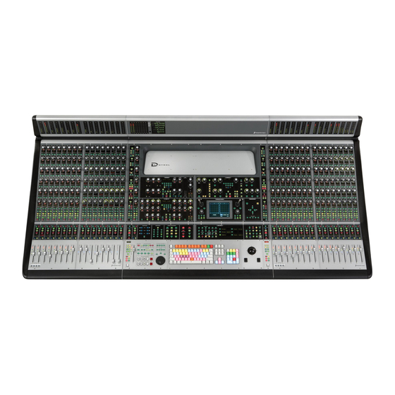
Dbl Press to Latch Dbl Press to Latch Talkback switch Bank Session Zoom/Navigation Select Management section section section Bank/Nudge Window Soft Keys Miscellaneous section Management section controls section Figure 3. D-Control Main Unit top panel Chapter 2: D-Control Overview 7... - Page 16 Meter Display Window Management and Session Management Sections The Meter display on the D-Control Main Unit can be set to show the output levels, or levels associated with a track or The Window Management and Session Management sections plug-in. See “Meter and Time Code Displays (Main Unit)” on on the D-Control Main Unit include controls for opening and page 112.
- Page 17 Keyboard/Trackball USB Connector The AC Power connector accepts a standard AC power cable. The USB connector on the back panel of the D-Control Main The D-Control Main Unit is auto power-selecting (100V to Unit links the computer keyboard and trackball on the Main 240V) and automatically works with a standard modular Unit to the Pro Tools system.
-
Page 18: D-Control Fader Module
The Power switch applies power to the Fader Module. Modifier Keys Ethernet Connector Each D-Control Fader Module has a set of four switches in its The Ethernet connector on the back panel of the D-Control lower left corner that duplicate the function of the Pro Tools Fader Module provides communication to Pro Tools. -
Page 19: D-Control Xmon Interface
D-Control XMON Interface D-Control monitoring is based on the XMON analog interface, which is remotely controlled from the D-Control monitoring section. XMON Front Panel XMON XMON Power switch Mute MIDI Receive indicator indicator Mute button Figure 6. XMON front panel... - Page 20 XMON Back Panel The back panel of the XMON interface includes connectors for all external analog audio inputs and outputs for D-Control. See “Audio Connections” on page 35. Cue Inputs Main Inputs Surround Inputs Stereo Inputs Cue Outputs Main Outputs...
-
Page 21: Part Ii Installation
Part II: Installation... -
Page 23: Chapter 3. Setting Up D-Control
Chapter 3: Setting Up D-Control This chapter explains how to set up 16-fader (Main Unit plus one Fader Module) and 32-fader D-Control systems (Main Unit plus two Fader Modules). D-Control Stand (16-Fader and 32-Fader Systems) Figure 1. Assembled D-Control stand The stand configurations for 16-fader and 32-fader systems have similar assembly procedures and the same number of parts (the crossbar and support rails are longer for a 32-fader system). - Page 24 Rear pan support rail Front pan support rail Left leg assembly Right leg assembly Rear crossbar assembly Figure 2. D-Control metal stand parts (2) Leg front caps Left and right side caps (2) Leg rear caps Figure 3. D-Control plastic stand parts...
- Page 25 Stand Hardware The following hardware is provided with the D-Control stand (spare pieces may be included). 1/4-inch-20 x 1/2-inch button head cap screw M6 x 8mm Phillips pan head screw 1/4-inch-20 x 1/2-inch socket head cap screw #10-32 x 1-inch socket head cap screw...
- Page 26 Placement of D-Control Preparing the Stand Legs In planning the placement of your D-Control, make sure to Before assembling the D-Control stand, make sure the floor in account for the dimensions of the assembled system, allowing the installation space is level and the areas directly under the for at least 1 inch (2.5 cm) of open space behind the finished...
- Page 27 It is important that you first build the stand slightly wider than its final dimensions, and leave all screws loose enough to allow the stand legs to move side-to-side relative to the rear crossbar and rails. After you install the D-Control units on the stand, you will then slide the leg assemblies inward and tighten all screws.
- Page 28 Locate the rear pan support rail, which is the larger of the two rails provided with the stand. Rear pan support rail Figure 12. Rear support rail in place on left stand leg Front pan support rail Figure 10. Side view of pan support rails D-Control Guide...
- Page 29 Position the front rail so that the edge with the V-shaped notch points toward the left stand leg. Notch indicating left side of front pan support rail Figure 14. V-shaped notch in front pan support rail Chapter 3: Setting Up D-Control 21...
-
Page 30: Installing D-Control Units
32-Fader System Installing D-Control Units If you are building a 32-fader D-Control, you can place the After the stand has been assembled, the next step is preparing Main Unit to the left, to the right, or in between the two Fader the D-Control Main Unit and Fader Modules for installation. - Page 31 (2) Figure 19. D-Control spacer plate (removed from a Fader Module) Remove the spacer plate from the right side of the Fader Figure 21. Installing the roll pin in the top of a D-Control unit Module. Front roll pin location Figure 22.
- Page 32 Lift successive units into place on the stand, being careful not to bend the pins in the units you installed previously. After the D-Control Main Unit and Fader Modules are pre- Slide the units together, guiding the pins in each unit into pared for installation, the units are placed on the stand in the the corresponding holes in the side of the next unit.
- Page 33 If necessary, use the ratcheting nylon strap to compress the D-Control units together by running the strap around the top part of the legs and across the D-Control units as shown in Figure 27. Make sure the nylon strap does not contact any switches or encoders on the surface.
- Page 34 Place the plastic side caps over each side of the unit, starting by hooking the front of each cap around the front part of the With the D-Control units in place and attached to the stand stand leg, then sliding the cap backward into place. The holes rails, you are now ready to install the plastic side caps.
-
Page 35: Installing A Video Display
Installing the Plastic Leg Caps Installing a Video Display You can install the D-Control plastic leg caps at any time. D-Control gives you two options for using a video display: To protect the plastic leg caps from damage, install them... - Page 36 Main Unit can support a VESA-style display that weighs up to 20 pounds (9 kg). The video display arm is packaged separately and includes hardware that is not needed for D-Control. The arm-mounting hardware is pre-installed in the bottom of the Main Unit.
- Page 37 Figure 42. Attaching the arm assembly with the top cap/threaded rod Adjust the display arm collar so that its stops prevent the arm assembly and video display from hitting the D-Control meter bridge. In most cases, the setscrew should not go into...
-
Page 38: Mounting D-Control Cables (Optional)
Alt/Option keys. Three different kinds of cable ties are provided with D-Con- trol. Velcro Rip Ties These ties can be affixed to the D-Control stand legs. Two pre-drilled holes inside each leg accept #8 x 1/2-inch self-tapping screws. Screw-mount Ties These ties can be affixed to the D-Control stand legs with the #8 x 1/2-inch self-tapping screws. -
Page 39: Moving The Keyboard And Trackball (Optional)
Replacing the Trackball with an (Optional) External Trackball or Mouse (Optional) You can move the trackball on the D-Control Main Unit to If you prefer to work with your own trackball or mouse, you the left of the computer keyboard. - Page 40 D-Control Guide...
-
Page 41: Chapter 4. Connecting D-Control
D-Control units require power, Ethernet and USB connections to operate with Pro Tools. An optional footswitch connection is also available on the Main Unit. The connectors on the back panel of the D-Control Main Unit are shown in Figure 48. - Page 42 You can connect two SPST (single-pole, single-throw) foot- that can simultaneously support D-Control over 10-BaseT and switch units to the D-Control Main Unit to control any of the other network traffic over 100-BaseT. This will allow you to following functions: use D-Control over a local area network.
-
Page 43: Audio Connections
Figure 49. XMON back panel XMON Monitoring System Connection D-Control connects to XMON with a single 15-pin cable. A 50-foot (15.25 m) cable is included with the D-Control Main Unit. The system supports up to an 80-foot (24.5 m) cable. - Page 44 • Listen Mic 2 (external), mic level (XMON provides 18V phantom power) Outputs • Main Control Room Outputs (8 channels), balanced or unbalanced, +4 dBu • Alt Control Room Outputs (8 channels), balanced or unbalanced, +4 dBu • Mini Control Room Outputs (2 channels), balanced or unbalanced, +4 dBu D-Control Guide...
- Page 45 • Cue 1 (2 channels), +4 dBu • Cue 2 (2 channels), +4 dBu • Cue 3 (2 channels), +4 dBu • Headphone (2 channels), to internal headphone jack • Studio Loudspeaker (2 channels) • Talkback/Slate Output (1 channel) Chapter 4: Connecting D-Control 37...
- Page 46 D-Control Guide...
-
Page 47: Chapter 5. Configuring D-Control
Refer to the Getting Started Guide that came with your system as they are physically arranged in the D-Control stand. You can set a Pro Tools system to use D-Control units in for instructions on installing or updating Pro Tools software. -
Page 48: Setting D-Control Preferences
Naming D-Control Units in Pro Tools Hold Control (Windows) or Command (Mac) and press the You can set the names for D-Control units from Pro Tools. Operation switch to exit. To name D-Control units in Pro Tools: Faders On/Off Choose Setup >... - Page 49 8 channels, from zero (no Custom Fader Bank) up to the total In the Soft Keys section, press the Operation switch repeat- number of channels on the D-Control system. edly to display the page that includes the Pan on Lower En- coder preference (“PanBot”).
- Page 50 Insert or Send on-screen makes its track Unit. the focused track on the D-Control Main Unit. For details on focusing a track on D-Control, see “Focusing a Track” on Right Custom Fader Justification Determines whether the Cus- page 117.
- Page 51 This preference applies when sends are displayed on To toggle the center meters between output and track metering: the D-Control rotary encoders. This metering follows Send In the Soft Keys section, press the Meter switch repeatedly to pre- or post-metering settings in Pro Tools.
-
Page 52: System Calibration
System Calibration Recalibrating D-Control Faders If a fader on a D-Control Unit shows response problems, you can recalibrate the faders with the Recal command in Utility mode. See “Recal” on page 133 for details. Calibrating the Output Meters You can calibrate the output meters on the Main Unit meter bridge from XMON, in order to match metering levels in Pro Tools with metering levels of external sources. - Page 53 Part III: Reference...
-
Page 55: Chapter 6. Channel Strip Controls
Rotary Encoder Section Channel Strips Each channel strip has six touch-sensitive rotary encoders The D-Control Main Unit has one central channel strip, called with LED ring, display, mode switches, and status indicators. the Focus Channel Strip, and each D-Control Fader Module has Rotary encoders control channel input, insert, send, pan, and 16 channel strips. - Page 56 When viewing a plug-in, the encoder Select switch is used to • Pad encoder B/M/P: toggles mic pre Pad on and off display and edit plug-in parameters on that channel’s rotary • Polarity encoder B/M/P: toggles mic pre Polarity encoders. D-Control Guide...
- Page 57 (such as the for displaying and editing pan, plug-in, mic pre, insert, or Digidesign PRE) are displayed on the channel strip’s rotary en- send parameters on the encoder section of the D-Control coders for editing. Microphone preamplifiers are declared in channel strip.
- Page 58 Each channel strip has a set of Channel Strip Function con- The Instruments View in Pro Tools contains MIDI controls trols for controlling channel selection and focus, mute, solo, that can be displayed on the bottom encoder of D-Control and record enable status, input monitor mode, and automa- channel strips.
- Page 59 Headroom Mode Shows the abbreviation “HR” followed by the Record Safe Mode To record safe a track from D-Control, hold remaining headroom in dB. Control (Windows) or Command (Mac) and press the track’s Level Mode Shows the track volume level in dB only.
- Page 60 AutoMatch indicators Modifier Key Switches Each D-Control Fader Module has a set of four switches in its lower left corner that duplicate the function of the Pro Tools computer keyboard modifiers. Channel Strip Fader section...
-
Page 61: Channel Strip Master Section
Make Inactive Inputs Outputs controls sides of the D-Control Main Unit, allowing easy access to Sends Plug-ins Plug-in Automation Plug-in Automation these controls from any mixing position. The operation of... - Page 62 Press either of the lighted Flip switches. Sends Inactive Switch When D-Control is in Make Inactive mode or Assign mode, The Sends switch invokes Sends Inactive mode and displays it is temporarily taken out of Flop mode, but the Flip the channel’s sends on its encoders.
- Page 63 Press the Enable Parameter switch. The Assign controls are used to assign inputs, outputs, inserts, and sends to channels. Each switch puts D-Control into a tem- Touch the rotary encoders or press the switches for the con- porary Assign mode in which elements are assigned or re- trols whose automation you want to toggle on or off.
- Page 64 Do one of the following: • Press the flashing encoder Select switch or press the flash- ing Assign switch to confirm the assignment. – or – • Press the flashing Escape switch to cancel the assign- ment. D-Control Guide...
- Page 65 MIDI Inputs and Outputs on Instrument Tracks Switch Info Switch The Assign Inputs and Assign Outputs switches can be used to The Switch Info switch can follow toggling or momentary be- assign the MIDI Inputs and Outputs on Instrument tracks. havior.
- Page 66 The “Write to Start/End/All” commands and the “Write to To manually Write to End: Next” command can also be invoked from the Soft Keys sec- tion of D-Control. Press the End switch during playback. To enable automatic Write to End on Stop:...
- Page 67 Changing Parameter Display on D-Control Channel Strips The Do To All and Do To Selected switches can be used to dis- The Do To All and the Do To Selected switches on D-Control play and edit pan, mic pre, insert, or send parameters across can be used in two different ways: to apply actions to multiple all tracks or all selected tracks in a session.
- Page 68 The Set to Default switch is used to reset parameters on the The Global Channel Strip Mode controls are used to display D-Control surface to their default values. This switch works in and edit pan, mic pre, insert, or send parameters across all both Normal and Custom Fader modes.
- Page 69 Global Inserts Switch Select/Focus Mode Switch and Indicators The Global Inserts switch displays inserts on the rotary encod- The Select/Focus Mode switch toggles the function of channel ers across all channels. Select switches between Select and Focus mode. In Select mode, channel Select switches are used to select channels in Pro Tools.
- Page 70 Custom the Custom Fader channels. Mix/Edit Groups switch Flip switch Groups Flip The Map switch has no effect on other D-Control channels in Tracks switch Lock switch Normal mode. Lock Tracks Flip Switch...
- Page 71 Two Talkback switches, located at the bottom of each Chan- Latch nel Strip Master section on the Main Unit, provide mirrored Automation Mode controls control of the D-Control Talkback function. To set the automation mode of one or more channels: Write Trim...
- Page 72 D-Control Guide...
-
Page 73: Chapter 7. Plug-In Controls
The first two send or insert positions will show on the encoder displays by default. Plug-ins of all types can be focused across multiple D-Control At the insert position where you want to make the assign- channels using Custom Fader Plug-ins mode. See “Plug-In ment, turn the encoder knob to select from the first level of... - Page 74 To set D-Control to automatically open plug-in windows: sponding D-Control section. Press the Operation switch in the D-Control Soft Keys sec- Press the Cycle switch in the Dynamics or EQ section to fo- tion repeatedly to display the page that includes the Channel cus successive dynamics or EQ plug-ins on that channel.
- Page 75 You can copy plug-in settings from a plug-in and paste them into another instance of the same plug-in directly from a channel strip on D-Control, from either the top-level view or the focused view of the plug-in. Chapter 7: Plug-in Controls 67...
-
Page 76: Displaying Dynamics Plug-In Gain Reduction On Channel Meters
Center Meter Display When the 8-channel center meters on plug-in whose parameters you want to enable for automation. the D-Control Main Unit is set to display levels for the focused track, the center meters show levels for up to two output... -
Page 77: Dynamics Section
Dynamics processing plug-ins may have widely varying con- The D-Control Dynamics section automatically focuses the trols, depending on their applications. The D-Control Dy- first dynamics plug-in on the channel displayed in the Focus namics Section provides dedicated knobs and switches to ac- Channel Strip on the Main Unit. - Page 78 The bottom encoder in this section controls the compression ratio or the range value for the current plug-in page, depend- ing on which indicator is lit. The Auto indicator under the en- coder knob lights when the displayed parameter is enabled for automation. D-Control Guide...
- Page 79 Gain/Hold and Threshold Controls Low Filter and High Filter Controls Hi Filter Low Filter Gain/Hold Filter Frequency encoder encoders auto auto auto Frequency Frequency Gain Hold indicator indicator Gain Hold Q/Slope Threshold encoders encoder auto auto auto Q/Slope Threshold Q/Slope Notch/Shelf switches and indicators...
- Page 80 If any channels are linked, their switches follow linked be- There are Channel Select switches for the following channels: havior. • L (Left) In Select mode, if the D-Control Channel Window Display • Lc (Left Center) preference is set to Yes, the Channel Select switches also • C (Center) change the channel display in the plug-in window.
- Page 81 Page switch lights. Pressing this switch steps through the Plug-in settings menu. pages for the currently displayed plug-in. To save a Dynamics plug-in setting from D-Control: Active paged controls are shown in the plug-in window by Press the Save As switch in the Edit and Display controls of colored outlines.
- Page 82 Dynamics section, even ing overwritten. when a different track is focused on D-Control. This switch lights when the plug-in focus is locked. Cycle Switch The Cycle switch steps through all available Dynamics Compare Switch plug-ins on the focused channel.
- Page 83 Dynamics Gain Controls and Meters Levels Gain Reduction Input Gain encoder auto Input Output Gain encoder auto Output Clip indicator Clip Compressor/Limiter Expander/Gate Input meter Output meter Gain Reduction Gain Reduction meter meter Input Output Level controls (left) and meters (right) in the Dynamics section Input and Output Gain Encoders The Input and Output Gain encoders control the input gain and output gain for the current plug-in.
-
Page 84: Eq Section
Displaying EQ Plug-ins EQ processing plug-ins may have widely varying controls, de- The D-Control EQ section automatically displays the first EQ pending on their applications. The D-Control EQ Section pro- plug-in on the channel that is focused in the Focus Channel vides dedicated knobs and switches to accommodate the wid- Strip on the Main Unit. - Page 85 High-Pass Filter and Low-Pass Filter Low Shelf/Peak and High Shelf/Peak Controls EQ Controls There are similar controls for high-pass and low-pass filters on There are similar controls for the low and high shelf/peak EQ the extreme left and right sides of the EQ section. bands on the left and right sides of the EQ section, just inside the high-pass and low-pass filter controls.
- Page 86 The bottom encoders in these EQ bands control the gain for each band. The Auto indicator under each encoder knob lights when the parameter is enabled for automation. Band In Switches The Band In switches in these EQ bands let you engage or bypass the corresponding EQ band in the plug-in. D-Control Guide...
- Page 87 If any channels are linked, their switches follow linked be- There are Channel Select switches for the following channels: havior. • L (Left) In Select mode, if the D-Control Channel Window Display • Lc (Left Center) preference is set to Yes, the Channel Select switches also • C (Center) change the channel display in the plug-in window.
- Page 88 Do one of the following: rent plug-in remains in the EQ section, even when a different • Hold Alt (Windows) or Option (Mac). track is focused on D-Control. This switch lights when the – or – plug-in focus is locked.
- Page 89 Safe Switch EQ Level Controls and Meters The Safe switch toggles the Safe button in the plug-in window, which protects existing automation for that plug-in from be- Levels ing overwritten. Input Gain encoder auto Cycle Switch Input The Cycle switch steps through all available EQ plug-ins on the focused channel.
- Page 90 D-Control Guide...
-
Page 91: Chapter 8. Transport And Navigation Controls
Chapter 8: Transport and Navigation Controls Transport Section The D-Control Transport section includes two complete sets of transport switches, switches for setting the transport mode, scrub/shuttle switches and controls, and advanced audition and locate switches. Audition switches Transport Mode switches... - Page 92 Trim Switch When the Timeline and Edit selections in the Edit window are unlinked, you can set the D-Control Transport to control The Trim switch places the transport in Trim/Scrub mode, playback of either the Timeline selection or the Edit selection.
- Page 93 Machine Online Switch monitoring mode for all record-enabled audio tracks in a ses- This feature has not been implemented for D-Control. sion. (This is the same as choosing the “Change Record En- abled Tracks to Auto Input” or “Input Only” in Pro Tools.)
- Page 94 When Audition mode is on, the Mark In and Mark Out Forward & Play Mode switches play a range of audio around the current Edit selec- tion. Forward & Play mode can be invoked by doing the following: D-Control Guide...
- Page 95 Channel Strips switch switch switch switch This function is currently not implemented for D-Control. External Machines switches Machine 3 Online Switch Track Arm from Channel Strips Switch This function is currently not implemented for D-Control. The Track Arm from Channel Strips switch displays track arm-...
-
Page 96: Zoom/Navigate Section
Edit and Transport windows. The Previous (Left) and Next (Right) Arrow switches move between fields, and the Up and Zoom Preset switches Down Arrow switches change the value. D-Control Zoom/Navigate Section Zoom Preset Switches Zoom Mode Switch The Zoom Preset switches recall the five horizontal Zoom pre- The Zoom Mode switch puts the arrow switches in Zoom sets in Pro Tools. -
Page 97: Bank/Nudge Section
The Bank/Nudge section controls the display of any channels The Bank Select matrix is used in Custom Fader modes to cre- in Normal mode on the D-Control surface. They are also used ate and select Custom Groups and Mix/Edit Groups, to select... - Page 98 D-Control Guide...
-
Page 99: Chapter 9. Management Sections
Edit window Mix window Plug-in window Edit Plug-In D-Control Window Management section MIDI Event Window Switch Memory Locations Window Switch The MIDI Event Window switch opens and closes the MIDI The Memory Locations Window switch opens and closes the Event window or brings it to the front. -
Page 100: Session Management Section
The QWERTY Disable switch temporarily disables the com- The Session Management section includes controls for ses- puter keyboard on D-Control, to prevent the possibility of ac- sion-wide management and save operations. cidental key presses. When the keyboard is disabled, this switch lights. -
Page 101: Soft Keys Section
The Soft Keys section provides access to a wide range of Pro Tools commands directly from the control surface. It also provides access to preferences and settings specific to D-Control. The section consists of six variable-function soft keys and displays, along with a matrix of mode switches that change the functions shown in the displays. - Page 102 • Disk Alloc: Setup > Disk Allocation • Preferences: Setup > Preferences Snap Switch • Peripherals: Setup > Peripherals This function is currently not implemented for D-Control. Edit Controls Group Switch Edit Function 1 Switch (Basic Edit Commands) The Group switch displays the following commands: •...
- Page 103 Edit Function 3 Switch Select/MIDI Controls The Edit Function 3 switch displays the following commands: Bank Select Switch Page 1 The Bank Select switch (“Bank Sel”) sets the Soft Keys to mir- • Duplicate: Edit > Duplicate ror the selection in the Bank Select Matrix. When Bank Select •...
- Page 104 The Operation switch controls behaviors that are specific to In the Soft Keys section, press the User switch repeatedly to D-Control, and that do not affect the Pro Tools on-screen dis- display the page (Page 1 or Page 2) where you want to add the play.
- Page 105 Record enabled. D-Control Main Unit. Brdcst (Broadcast) Determines whether the XMON monitor- Faders (Faders On/Off) Temporarily turns off D-Control faders ing system is in Broadcast mode, which prevents AFL and PFL to prevent fader movement when monitoring a mix. solo modes from changing the XMON Control Room Input ChanWn (Channel Window Display) Determines whether dis- source.
- Page 106 Snap Back Causes all Latch or Write enabled tracks to exit their current automation pass and return instantly to the pre- viously written automation levels. During playback, stops writing of automation without applying any AutoMatch ramping. D-Control Guide...
- Page 107 Hold Start+Alt (Windows) points in an automation pass performed with the optional or Control+Option (Mac) while pressing the Auto ToStrt D-Control surround panner. switch to configure the mode to remain enabled after an au- tomation pass.
-
Page 108: Miscellaneous Controls Section
Cut Switch Cuts the current edit selection. The Edit/Timeline switch toggles the Selection indicator val- ues and the D-Control transport function between the edit se- Copy Switch Copies the current edit selection to the Clip- lection and the timeline selection. The indicators above the board. - Page 109 Track Size Switches The Track Size Up and Down switches increase and decrease the height of all tracks where a selection or edit cursor is present. Explode Switch The Explode switch invokes the Zoom Toggle command in Pro Tools, which zooms in on the current edit selection and sets the track height to the size specified in the Pro Tools Dis- play preferences.
- Page 110 D-Control Guide...
-
Page 111: Chapter 10. Monitor And Meter Sections
The Monitor section includes a full set of controls for the control room monitoring, headphone/cue, and talkback/listenback sections of D-Control. All input and output connections to the D-Control monitoring system are made on the XMON interface, which is connected to the D-Control console with the XMON cable, and remotely controlled from this section. -
Page 112: Control Room Monitoring System
(non-latching) behavior, allowing only one source to be monitored at a time. Inputs However, D-Control has a Sum mode that allows multiple in- Stereo 1 put sources to be monitored at the same time. When Sum mode is on, multiple input source switches can be active. - Page 113 The Control Room monitor system has three outputs: Setup Switch • Main Control Room Outputs (8 channels) This function is currently not implemented for D-Control. • Alt Control Room Outputs (8 channels) • Mini Control Room Outputs (2 channels) Calibration Mode Switch Only one output can be active at a time.
- Page 114 If the Mute switch on the XMON interface front panel is acti- – or – vated, the Mute switch on D-Control must be used to unmute • To display output in dB, press the Calibration Mode the monitor system. (Outputs cannot be unmuted from switch so that it is unlit.
- Page 115 Output Channel Select Controls Individual Output Trim Mode Each output channel can be trimmed individually for each of the three control room outputs (Main, Alt, and Mini), allow- ing you adjust the channel balance for each set of control room speakers. Trim values are stored for each of the three Channel Select switches outputs.
- Page 116 Solo Mode Controls To set the AFL or PFL level to its default setting: Press the AFL or PFL switch in the D-Control Monitor sec- tion. Hold Alt (Windows) or Option (Mac) and touch the AFL/PFL AFL/PFL Level control rotary encoder.
-
Page 117: Headphone/Cue System
Headphone/Cue System The Headphone/Cue system is a two-channel system with four stereo input sources and five available stereo outputs. Headphone/Cue Output Controls Headphone Studio Loudspeaker Level control Level control Headphones Studio LS Headphone Studio Loudspeaker On/Off switch On/Off switch Cue Output Level controls Cue 1 Cue 2... -
Page 118: Talkback/Listen System
“Int TB” and the level in output. Headphone Outputs A Headphone output is located on the underside of the D-Control Main Unit, near the front right side. The other four pairs of headphone outputs are available on the XMON inter- face. D-Control Guide... - Page 119 Listen Mic Level control can still be Two Talkback switches, located at the bottom of each Chan- adjusted, to prepare for the next time an input is activated. nel Strip Master section on the Main Unit, provide control of the D-Control Talkback function. Write Trim Touch...
-
Page 120: Meter And Time Code Displays (Main Unit)
The meter bridge on the Main Unit includes eight 32-segment LED bar graphs for displaying output levels or the level of the track focused in the Focus Channel Strip, depending on the D-Control Meter Preferences setting. The top LED is red and indicates clip- ping on the corresponding channel. -
Page 121: Meter Displays (Fader Module)
B–20 dB This reference level is designed specifically for broadcast applications, with a lower threshold for the change to amber. The settings lights a single amber LED at –20 dB across the D-Control meter bridge. This mode also changes the meter LED colors: LEDs above –20 dB through –13 dB are green, and the LEDs from –12 dB to 0 dB are amber, with 0 dB remaining red. - Page 122 D-Control Guide...
-
Page 123: Chapter 11. Operating Modes
Chapter 11: Operating Modes The power and flexibility of D-Control lies in its different op- Press the flashing encoder Select switch or press the flashing erating modes, which let you customize the behavior of its Assign switch to confirm the assignment. - Page 124 • Press the flashing encoder Select switch to confirm the as- You can make Inputs, Outputs, Inserts, Sends, and entire signment. tracks active or inactive directly from D-Control by entering a – or – temporary Make Inactive mode. • Press the flashing Escape switch to cancel the assign- ment.
- Page 125 Press the Select switch under the name of the plug-in you want to focus. The plug-in parameters are displayed in the You can focus any track in a session on the D-Control Focus channel’s encoders. Channel Strip. This mirrors the track controls in the channel...
- Page 126 Select Muting Sends switch become Automation Safe switches. While in this mode, You can mute sends directly from D-Control by setting the ap- pressing a Bypass/Mute/Pre switch on a plug-in or send pro- propriate mode for the Bypass/Mute/Pre switch.
- Page 127 Flip Mode To assign an individual insert or send to a flipped encoder: On the channel where you want to make the assignment, Channels in Normal mode can use Flip Mode, which transfers press the Inserts or Sends switch to display the corresponding controls from a row of encoders to the channel faders.
-
Page 128: Inline Console Mode
With the Custom Faders feature, you can temporarily set aside on D-Control. channel strips on D-Control and focus them on your own cus- An input signal (for example, from a Digidesign PRE) is tomized groups of tracks, on Pro Tools Mix and Edit groups, brought into an Auxiliary Input track, and routed to an Audio on specific track types, or on plug-in controls. - Page 129 Displaying Hidden Tracks in Custom Faders plug-in on the two available Custom Fader channel banks. A You can set D-Control to show hidden tracks in the Custom special expanded Plug-In mode focuses the plug-in header Fader views. You can then mix those hidden tracks, but you controls (such as Bypass, Compare and Safe) on the channel cannot select or record-enable them.
- Page 130 Mix/Edit groups in Pro Tools. you want to recall. D-Control Custom Groups are not reflected on-screen in Pro Tools. Custom Groups are saved in the Pro Tools session The Bank Select switches remember their previous mode...
- Page 131 To add channels to a Custom Group: To show a Mix/Edit group in the Custom Fader channels: Recall the Custom Group you want to edit. Press the Groups switch in the left or right Custom Fader section. Press the Edit switch in the Bank Select section. The Edit switch flashes to indicate Custom Groups Edit mode.
- Page 132 B/M/P (Bypass/Mute/Pre) encoder switches. The pres- section. ence of a switched parameter is indicated by the Pre indicator above the corresponding B/M/P switch. Press the Bank Select switch to display track types in the Soft Keys section. D-Control Guide...
- Page 133 To see what parameter is controlled by a B/M/P switch, press Link To link channels of a multi-mono plug-in, press the Mute the Switch Info switch. switch that corresponds to “Link” in the channel displays. This toggles the Master Link button in the Plug-In window In some cases, the same control may be mapped to both an encoder knob and its corresponding switch, allowing you to Target Stream To target a particular multi-mono plug-in chan-...
- Page 134 D-Control operation. Plug-in mapping files (.pim) files can be imported and ex- ported for use with other D-Control and D-Command con- To map an encoder to a fader (Custom Groups mode or Mix/Edit soles. Groups mode):...
- Page 135 To clear mapping (Plug-In mode): In Custom Faders Plug-In Map mode, display the plug-in whose map you want to clear. Press the Set to Default switch. Press the Do To All switch. Press the Select switch on any of the Custom Fader channel strips.
- Page 136 D-Control Guide...
-
Page 137: Appendix A. Utility Mode
Fader Module Modifier Key sequence for Utility mode A D-Control unit is online if Pro Tools is running and the unit is declared in the Peripherals page of the Setups dialog. A unit is offline when Pro Tools is not running, or if it is not declared Navigating Utility Mode on a system that is running Pro Tools. -
Page 138: Exiting Utility Mode
These names appear in the Pro Tools Peripherals dia- Press the flashing Utility switch (Main Unit). log, and must be unique so as to identify each D-Control unit correctly. This is especially important if your system is on an –... -
Page 139: D-Control Test Pages
Press the Soft Key (Main Unit) or the encoder Select switch There are three test levels for Ethernet communication on (Fader Module) that corresponds to “Mendec.” D-Control: Internal, Mendec, and External. These tests can as- sist Digidesign Technical Support should you ever experience To exit the Mendec Ethernet test: difficulty with Ethernet communication between D-Control Press the flashing Soft Key (Main Unit) or encoder Select... - Page 140 Press the Soft Key that corresponds to “Red,” “Yellow,” or To exit Meter Bridge LED Test mode: “Green” to test all LEDs of the corresponding color. Press the Soft Key (Main Unit) or encoder Select switch (Fader Module) that corresponds to “Escape.” D-Control Guide...
- Page 141 Press the Soft Key (Main Unit) or encoder Select switch (Fader Module) that corresponds to “Escape.” In addition, under conditions of heavy use, the D-Control fader motor protection feature may disengage a fader if it is in danger of overheating. The Recal command reengages any dis- engaged faders.
-
Page 142: Resetting D-Control To Factory Defaults
Defaults “Bright.” Turn the Scrub/Shuttle wheel (Main Unit) or any encoder The Reset (Factory Default) page lets you reset the D-Control knob (Fader Module) to change the brightness value. Bright- Main Unit and Fader Modules to their factory default settings. - Page 143 To set the display contrast: pressing the footswitch is the functional equivalent of press- ing the corresponding switch on the D-Control Main Unit. From the Preferences page, press the Soft Key (Main Unit) or the encoder Select switch (Fader Module) that corresponds to Each Footswitch Settings page has four options: “Contrast.”...
- Page 144 D-Control Guide...
-
Page 145: Appendix B. Audio Connections And Pinouts
Appendix B: Audio Connections and Pinouts All external D-Control audio connections are made to the back panel of the XMON interface, shown below. All audio connectors are standard female DB-25 connectors. The connector for communication with D-Control is a 15-pin female connector. - Page 146 Main 4 (Rc) Stereo Input 3 (Left) Main 5 (R) Stereo Input 3 (Right) Main 6 (Ls) Stereo Input 4 (Left) Main 7 (Rs) Stereo Input 4 (Right) Main 8 (LFE) SHIELD GND connector housing SHIELD GND connector housing D-Control Guide...
-
Page 147: 15-Pin Connector Pinouts
Alt 1 (L) Alt 2 (Lc) Alt 3 (C) Alt 4 (Rc) 15-pin connector (user view) Alt 5 (R) XMON to D-Control Connector Pinouts Alt 6 (Ls) Alt 7 (Rs) XMON to D-Control Pinouts Signal Name Hot (+) Cold (–) - Page 148 D-Control Guide...
-
Page 149: Index
Index Numerics Automation Trim switch 51 Automation Write controls 58 9-Pin Remote switch 85 Write to All 58 Write to All Enabled 58 Write to Current 58 Write to End 58 Actions switch (automation) 98 Write to Start 58 After-Fader Listen (Monitor section) 108 Auxiliary Input tracks 120 All Enabled switch (automation) 58 All Notes Off switch 92... - Page 150 Cycle switch (plug-ins) 74, 81 Filter Q /Slope controls (Dynamics plug-ins) 71 Flip mode 53, 119 and Instrument tracks 50 Flip switch (Custom Fader mode) 62 D-Control Units declaring 39 naming 40 Dim function 109, 111 Dim Level control 105...
- Page 151 Memory Location switch 95 selecting 104 meter displays (Fader Module) 113 stereo 104 meter displays (Main Unit) 112 summing 104 Meter preferences surround 104 Preferences (D-Control) trimming 104 Meters 43 Insert/Assemble switch 87 Meter switch 96 inserts meters 8 assigning 115, 116, 119...
- Page 152 Page switch (plug-ins) 73 operational 4 Page switches (channel strips) 49 system 4 Pan on Lower Encoder preference 41 resetting D-Control units (Utility mode) 134 Pan switch (automation) 57 Rotary Encoder Velocity mode 41 Pan switches 49 rotary encoders 47...
- Page 153 3, 16 Write to End (automation) 58 finishing 25, 26 Write to Start (automation) 58 hardware 17 installing D-Control units 22, 23, 24 leveling 18 Start (Start/End/Length) switch 100 XMON 137 Start switch (automation) 58 back panel overview 12...
- Page 154 DIGIDESIGN TECHNICAL SUPPORT (USA) PRODUCT INFORMATION (USA) INTERNATIONAL OFFICES Visit our Digidesign Web site 2001 Junipero Serra Boulevard Tel: 650.731.6100 Tel: 650.731.6102 for contact information Daly City, CA 94014-3886 USA Fax: 650.731.6384 Fax: 800.333.2137 Tel: 650.731.6300 Fax: 650.731.6399...
Need help?
Do you have a question about the D-Control and is the answer not in the manual?
Questions and answers