Table of Contents
Advertisement
Owner's Manual
Manual Ranging MultiMeter
Model 82345
CAUTION: Read, understand and
follow Safety Rules and Operating
Instructions in this manual before
using this product.
© Sears, Roebuck and Co., Hoffman Estates, IL 60179 U.S.A.
www.craftsman.com
! Safety
! Operation
! Maintenance
! Español
080806
Advertisement
Table of Contents

Related Manuals for Craftsman 82345


Summary of Contents for Craftsman 82345
- Page 1 Owner’s Manual Manual Ranging MultiMeter Model 82345 ! Safety CAUTION: Read, understand and follow Safety Rules and Operating ! Operation Instructions in this manual before ! Maintenance using this product. ! Español © Sears, Roebuck and Co., Hoffman Estates, IL 60179 U.S.A.
-
Page 2: Table Of Contents
TABLE OF CONTENTS Page Warranty Safety Instructions Safety Symbols Control and Jacks Symbols and Annunciators Specifications Battery Installation Operating Instructions DC Voltage Measurements AC Voltage Measurements DC Current Measurements Resistance Measurements Temperature Measurements Diode Test Continuity Test Battery Test Data Hold Maintenance Replacing the Battery Replacing the Fuse... -
Page 3: Warranty
ONE YEAR FULL WARRANTY ONE YEAR FULL WARRANTY ON CRAFTSMAN MULTIMETER If this CRAFTSMAN Multimeter fails to give complete satisfaction within one year from the date of purchase, RETURN IT TO THE NEAREST SEARS STORE OR OTHER CRAFTSMAN OUTLET IN THE UNITED STATES, and Sears will replace it, free of charge. -
Page 4: Safety Instructions
SAFETY INSTRUCTIONS This meter has been designed for safe use, but must be operated with caution. The rules listed below must be carefully followed for safe operation. NEVER apply voltage or current to the meter that exceeds the specified maximum: Input Protection Limits Function Maximum Input... -
Page 5: Safety Symbols
SAFETY SYMBOLS This symbol adjacent to another symbol, terminal or operating device indicates that the operator must refer to an explanation in the Operating Instructions to avoid personal injury or damage to the meter. This WARNING symbol indicates a WARNING potentially hazardous situation, which if not avoided, could result in death or serious injury. -
Page 6: Control And Jacks
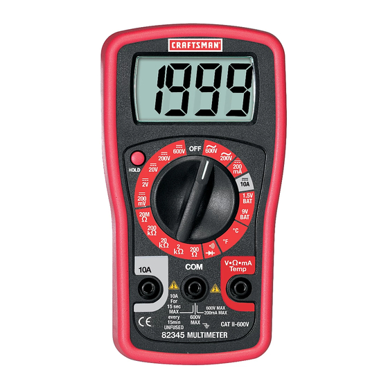
CONTROLS AND JACKS 1. LCD Display 2. Hold push-button 3. Rotary function dial 4. Test lead jack for voltage, milli-amp, resistance and temperature 5. Test lead jack for amps 6. COM test lead jack Note: Tilt stand and battery access is on the rear of unit. -
Page 7: Specifications
SPECIFICATIONS Function Range Accuracy DC Voltage 200.0mV (V DC) 2.000V !(0.5% reading + 2 digits) 20.00V 200.0V 600V !(0.8% reading + 2 digits) AC Voltage 200.0V (V AC) !(1.2% reading + 10 digits) 600V (40 - 400Hz) DC Current 200.0mA !(1.5% reading + 2 digits) (A DC) 10.00A... - Page 8 SPECIFICATIONS NOTES: Accuracy specifications consist of two elements: • (% reading) – This is the accuracy of the measurement circuit. • (+ digits) – This is the accuracy of the analog to digital converter. Accuracy is stated at 65 F to 83 F (18 C to 28 C) and less than...
- Page 9 SPECIFICATIONS Operating Temp F to 104 F (0 C to 40 Storage Temp F to 140 F (-20 C to 60 Relative Humidity Maximum relative humidity 80% for temperatures up to 31°C decreasing linearly to 50% relative humidity at 40°C. Operating Altitude 7000ft (2000 meters) maximum.
-
Page 10: Battery Installation
BATTERY INSTALLATION WARNING: To avoid electric shock, disconnect the test leads from any source of voltage before removing the battery/fuse cover. 1. Disconnect the test leads from the meter. 2. Remove the rubber holster (if in place). 3. Remove the two screws securing the rear cover using a Phillips head screwdriver. -
Page 11: Operating Instructions
OPERATING INSTRUCTIONS WARNING: Risk of electrocution. High-voltage circuits, both AC and DC, are very dangerous and should be measured with great care. 1. ALWAYS turn the function switch to the OFF position when the meter is not in use. 2. Press the HOLD button to freeze a displayed reading NOTE: On some low AC and DC voltage ranges, with the test leads not connected to a device, the display may show a random, changing reading. -
Page 12: Ac Voltage Measurements
AC VOLTAGE MEASUREMENTS WARNING: Risk of Electrocution. The probe tips may not be long enough to contact the live parts inside some 240V outlets for appliances because the contacts are recessed deep in the outlets. As a result, the reading may show 0 volts when the outlet actually has voltage on it. -
Page 13: Dc Current Measurements
DC CURRENT MEASUREMENTS CAUTION: Do not make current measurements on the 10A scale for longer than 30 seconds. Exceeding 30 seconds may cause damage to the meter and/or the test leads. 1. Insert the black test lead banana plug into the negative (COM) jack. -
Page 14: Resistance Measurements
RESISTANCE MEASUREMENTS WARNING: To avoid electric shock, disconnect power to the unit under test and discharge all capacitors before taking any resistance measurements. Remove the batteries and unplug the line cords. 1. Set the function switch to the highest !! position. -
Page 15: Diode Test
DIODE TEST 1. Insert the black test lead banana plug into the negative COM jack and the red test lead banana plug into the positive diode jack. 2. Turn the function switch to the / •))) position. 3. Touch the test probes to the diode under test. -
Page 16: Battery Test
BATTERY TEST 1. Insert the black test lead banana plug into the negative COM jack and the red test lead banana plug into the positive V jack. 2. Select the 1.5V or 9V BAT position using the function switch. 3. Connect the red test lead to the positive side of the 1.5V or 9V battery and the black test lead to the negative side of the 1.5V or 9V battery. -
Page 17: Maintenance
MAINTENANCE WARNING: To avoid electric shock, disconnect the test leads from any source of voltage before removing the back cover or the battery or fuse cover. WARNING: To avoid electric shock, do not operate your meter until the battery and fuse cover are in place and fastened securely. -
Page 18: Replacing The Battery
REPLACING THE BATTERY WARNING: To avoid electric shock, disconnect the test leads from any source of voltage before removing the battery cover. 1. When the battery become exhausted or drop below the operating voltage, “ ” will appear in the lower left corner of the LCD display. -
Page 19: Troubleshooting
Electrical Testing (Item No. 82303) at your local Sears store. 2. Call our Customer Service Line 1-888-326-1006. SERVICE AND PARTS Item Number Description 82374 Fuse kit 93894 9V battery 82378 Set of black and red Test Leads 82345-CS Rear cover screws 82377 Temperature probe...