Schwinn Journey 2.0 Recumbent Bike Assembly Manual
Assembly and owner's manual
Hide thumbs
Also See for Journey 2.0 Recumbent Bike:
- Service manual (60 pages) ,
- Assembly manual (44 pages) ,
- Owner's manual (28 pages)

Related Manuals for Schwinn Journey 2.0 Recumbent Bike


Summary of Contents for Schwinn Journey 2.0 Recumbent Bike
- Page 1 230 / 430 / 470 / Manual en Español Latino Americano: ASSEMBLY MANUAL / OWNER’S MANUAL http://www.schwinnfitness.com...
-
Page 2: Table Of Contents
Table of ConTenTs Important Safety Instructions - Assembly Operations Safety Warning Labels / Serial Number 4 Adjustments Specifications Power Up / Idle Mode Before Assembly Quick Start Program Parts User Profiles Hardware Pausing or Stopping Tools Results / Cool Down Mode Assembly GOAL TRACK Statistics Moving the Machine Console Service Mode... -
Page 3: Important Safety Instructions - Assembly
ImporTanT safeTy InsTruCTIons -assembly This icon means a potentially hazardous situation which, if not avoided, could result in death or serious injury. Obey the following warnings: Read and understand all warnings on this machine. Carefully read and understand the Assembly instructions. • Keep bystanders and children away from the product you are assembling at all times. -
Page 4: Safety Warning Labels / Serial Number
safeTy WarnIng labels and serIal number • Read, understand and obey all warnings on this machine. • Keep children away. • Not intended for use by anyone under 14 years of age. • Prior to use, read and understand the Owner’s Manual. •... -
Page 5: Specifications
speCIfICaTIons Maximum User Weight: 300 lbs. (136 kg) 49.9” (126.8 cm) Power Requirements: Operational Voltage: Operational Voltage 9VDC Operating Current: 1500 mA Regulatory Approvals: A C Power Adapter: U L listed, CEC certified (or equivalent), 64” Rated 120V 60Hz Input, 9VDC, 1500mA (162.5 cm) Output. Class 2. 27.7” (70.3 cm) This product, its packaging, and components contain chemicals known to the State of California to cause cancer, birth defects, or reproductive harm. This Notice is provided in accordance with California’s Proposition 65. If you would like additional information, please refer to our website at www.nautilus.com/prop65. -
Page 6: Parts
parTs Item Description Item Description Console AC Adapter Water Bottle Holder Left Pedal Seat Back Front Stabilizer Cover Right Pedal Seat Frame Assembly Upper Shroud Seat Bottom Shroud Cap Seat Adjustment Handle Console Mast Rear Stabilizer MP3 Cord Frame... -
Page 7: Hardware
HardWare / Tools Description Description Item Item Button Head Hex Screw, M8x20 Phillips Head Screw, M5x12 Button Head Hex Screw, M6x12 Lock Washer, M6 Flat Washer, M8 Curved Washer, M6 Lock Washer, M8 Phillips Head Screw, M6x25 Flat Washer, M6 Curved Washer, M8 Tools Included Not Included (recommended) 4 mm 6 mm... -
Page 8: Assembly
assembly 1. Attach Stabilizers to Frame Note: Hardware is pre-installed and not on the Hardware Card. *... - Page 9 2. Attach the Seat Frame Assembly to the Seat Rail NOTICE: Do not crimp the Heart Rate Cable. Once all hardware has been inserted, be sure to fully tighten it.
- Page 10 3. Attach Seat Pads to Seat Frame Assembly...
- Page 11 4. Attach Cover to Frame Assembly...
- Page 12 5. Attach Seat Adjustment Handle to Frame Assembly...
- Page 13 6. Connect the Cables and Attach the Console Mast to Frame Assembly NOTICE: Do not crimp Console Cables.
- Page 14 7. Remove Hardware from Console NOTICE: Do not crimp the cable. Note: Hardware is pre-installed and not on the Hardware Card. * 8. Connect Cables and Attach Console to Frame Assembly NOTICE: Align the clips on the cable connectors and make sure the connectors lock. Do not crimp cables.
- Page 15 9. Attach Pedals to Frame Assembly NOTICE: The Left Pedal is reverse-threaded. Be sure to attach Pedals on the proper side of the Bike. Orientation is based from a seated position on the bike. The Left Pedal has an “L”, the Right Pedal an “R”.
- Page 16 10. Attach Water Bottle Holder to Frame Assembly...
- Page 17 11. Connect AC Adapter to Frame Assembly 12. Final Inspection Inspect your machine to ensure that all hardware is tight and components are properly assembled. Be sure to record the serial number in the field provided at the front of this manual. Do not use until the machine has been fully assembled and inspected for correct performance in accordance with the Owner’s Manual.
-
Page 18: Moving The Machine
before you sTarT Moving the Bike The machine may be moved by one or more persons depending on their physical abilities and capacities. Make sure that you and others are all physically fit and able to move the machine safely. Remove the power cord. -
Page 19: Leveling The Machine
Leveling the Bike Levelers are found on each side of the Rear Stabilizer and on the Frame Rail. On the Rear Stabilizer, turn the knob to adjust the stabilizer foot. To adjust the leveler on the Frame Rail: 1. L oosen the upper locking nut. Turn the leveler to adjust the height. Do not adjust the levelers to such a height that they detach or unscrew from the machine. Injury to you or damage to the machine can occur. -
Page 20: Important Safety Instructions
ImporTanT safeTy InsTruCTIons This icon means a potentially hazardous situation which, if not avoided, could result in death or serious injury. Before using this equipment, obey the following warnings: Read and understand the complete Manual. Keep the Manual for future reference. R ead and understand all warnings on this machine. If at any time the Warning stickers become loose, unreadable or dislodged, contact Nautilus Customer Service for replacement stickers. ® • Children must not be let on or near to this machine. Moving parts and other features of the machine can be dangerous to children. • Not intended for use by anyone under 14 years of age. • Consult a physician before you start an exercise program. Stop exercising if you feel pain or tightness in your chest, become short of breath, or feel faint. Contact your doctor before you use the machine again. Use the values calculated or measured by the machine’s computer for reference purposes only. -
Page 21: Features
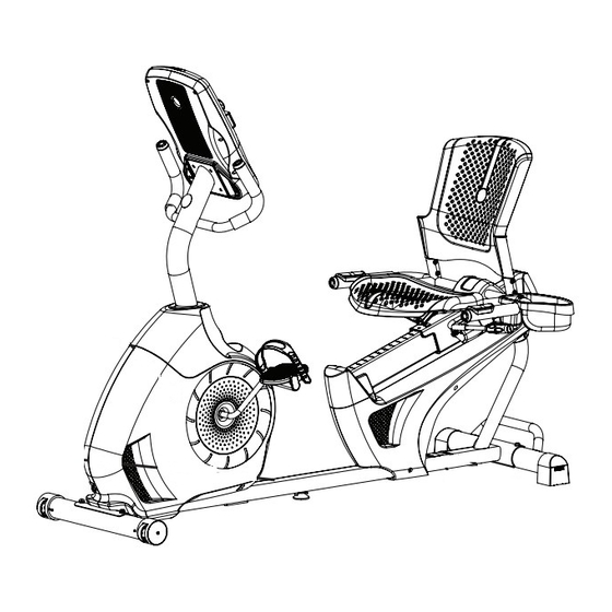
feaTures Console Leveler MP3 Input Transport Handle USB Port Seat Adjustment Knob Media Tray Water Bottle Holder Adjustable Seat Speakers Contact Heart Rate (CHR) Sensors Fully Shrouded Flywheel Handlebar, Side Power Connector Pedal Transport Wheel Storage Bin Stabilizer Handlebar, Upright... -
Page 22: Console Features
Console Features The Console provides important information about your workout and lets you control the resistance levels while you exercise. The Console features the Schwinn Dual Track display with touch control buttons to navigate you through the exercise ™ programs. Upper Display 40% 70% 40% 70% QUICK PAUSE/ ST ART Lower Display PROGRAMS GOAL TRACK Resistance Level Quick Buttons Resistance Level Quick Buttons CURRENT WORKOUT LAST WORKOUT LAST 7 DA YS Achievement Indicator Lights Keypad Functions Resistance Increase () button- Increases the workout resistance level Resistance Decrease () button- Decreases the workout resistance level QUICK START button- Begins a Quick Start workout PROGRAMS button- Selects a category and workout program PAUSE / END button- Pauses an active workout, ends a paused workout, or goes back to the previous screen GOAL TRACK button-Displays the Workout Totals and Achievements for the selected User Profile Increase () button- Increases a value (age, time, distance, or calories) or moves through options... - Page 23 Resistance Level Quick Buttons- Shifts the resistance levels to the setting quickly during a workout Achievement Indicator Lights- when a workout result is reviewed, the achievement indicator light will activate. Schwinn Dual Track™ Display Upper Display Data User Display Achievement Display 40% 70% Program Display The Program Display shows information to the User and the grid display area shows the course profile for the program. Each column in the profile shows one interval (workout segment). The higher the column, the higher the resistance level. The flashing column shows your current interval. Intensity Display The Intensity Display shows the level of work at that moment based on the current resistance level. Heart Rate Zone Display The Heart Rate Zone shows which zone the current heart rate value falls into for the current User. These Heart Rate Zones can be used as a workout guide for a certain target zone (anaerobic, aerobic, or fat burn). Consult a physician before you start an exercise program. Stop exercising if you feel pain or tightness in your chest, become short of breath, or feel faint. Contact your doctor before you use the machine again. Use the values calculated or measured by the machine’s computer for reference purposes only.
- Page 24 40% 70% Lower Display Data USE/ GOAL TRACK The Lower Display shows the Workout Values. and can be customized for each User (Consult the “Edit User Profile” section of this manual). CURRENT WORKOUT Speed LAST WORKOUT LAST 7 DA YS The Speed display field shows the machine speed in miles per hour (mph) or kilometers per hour (km/h). Time The TIME display field shows the total time count of the workout, the average Time for the User Profile, or the total operational time of the machine. Note: If a Quick Start workout is performed for more than 99 minutes and 59 seconds (99:59), the units for Time will shift to hours and minutes ( 1 hour, 40 minutes ). Distance The Distance display shows the distance count (miles or km) in the workout. Note: T o change the measurement units to English Imperial or metric, refer to the “Console Setup Mode” section in this manual. Level The LEVEL display shows the current resistance level in the workout. The RPM display field shows the pedal revolutions per minute (RPM). Heart Rate (Pulse) The Heart Rate display shows the beats per minute (BPM) from the heart rate monitor. When a heart rate signal is received by the Console, the icon will flash.
- Page 25 Contact Heart Rate Sensors Contact Heart Rate (CHR) sensors send your heart rate signals to the Console. The CHR sensors are the stainless steel parts of the Handlebars. To use, put your hands comfortably around the sensors. Be sure that your hands touch both the top and the bottom of the sensors. Hold firm, but not too tight or loose. Both hands must make contact with the sensors for the Con- sole to detect a pulse.
- Page 26 The graph is a brief guideline, describing the generally suggested target heart rates based on age. As noted above, your opti- mal target rate may be higher or lower. Consult your physician for your individual target heart rate zone. Note: A s with all exercises and fitness regimens, always use your best judgment when you increase your exercise time or intensity.
-
Page 27: Operations
operaTIons What to Wear Wear rubber-soled athletic shoes. You will need the appropriate clothes for exercise that allow you to move freely. How Often Should You Exercise Consult a physician before you start an exercise program. Stop exercising if you feel pain or tightness in your chest, become short of breath, or feel faint. Contact your doctor before you use the machine again. Use the values calculated or measured by the machine’s computer for reference purposes only. The heart rate displayed on the console may be inaccurate and should be used for reference only. • 3 times a week for 30 minutes each day. • Schedule workouts in advance and try to follow the schedule. -
Page 28: Quick Start Program
Initial Setup During the first power-up, the Console should be setup with the date, time and your preferred measurement units. 1. D ate: Push the Increase/Decrease buttons to adjust the currently active value (flashing). Push the Left/Right buttons to change which segment is the currently active value (month / day / year). 2. P ush OK to set. 3. T ime: Push the Increase/Decrease buttons to adjust the currently active value (flashing). Push the Left/Right buttons to change which segment is the currently active value (hour / minute / AM or PM). 4. P ush OK to set. 5. U nits of Measurement: Push the Increase/Decrease buttons to adjust between “MILES” (Imperial English) or “KM” (metric). 6. Push OK to set. The Console goes back to the Power-Up / Idle Mode screen. Note: To adjust these selections, consult the “Console Set-Up Mode” section. Quick Start ( Manual ) Program The Quick Start ( Manual ) program lets you start a workout without entering any information. During a Manual Workout, each column represents a 2 minute time period. The active column will advance across the screen every 2 minutes. If the workout lasts for more than 30 minutes, the active column is fixed on the farthest column on the right and pushes the previous columns off the display. - Page 29 Select a User Profile Every workout is saved to a User Profile. Be sure to select the proper User Profile before starting a workout. The last User that completed a workout will be the default user. User Profiles are assigned the default values until they are customized by editing. Be sure to edit the User Profile for more accurate calorie and heart rate information. From the Power-Up Mode screen, push the Increase() or Decrease() buttons to select one of the User Profiles. The Console will display the name of the User Profile and the User Profile Icon. Edit User Profile 1. F rom the Power-Up Mode screen, push the Increase() or Decrease() buttons to select one of the User Profiles. 2. P ush the OK button to select the User Profile. 3. T he Console display shows the EDIT prompt and the current User Profile name. Push OK to start the Edit User Profile option. T o exit the Edit User Profile option, push the PAUSE/END button and the console will go back to the Power-Up Mode screen. 4. T he Console display shows the NAME prompt and the current User Profile name. Note: The User name will be blank if this is the first edit. The name of a User Profile is limited to 10 characters. T he currently active segment will flash. Use the Increase/Decrease buttons to move through the alphabet and blank space (found between A and Z).
- Page 30 9. T he Console will go to the Power-Up Mode screen with the user selected. Reset a User Profile 1. F rom the Power-Up Mode screen, push the Increase() or Decrease() buttons to select one of the User Profiles. 2. P ush the OK button to select the User Profile. 3. T he Console display shows the current User Profile name and the EDIT prompt. Push the Increase() or Decrease() buttons to change the prompt. Note: To exit the Edit User Profile option, push the PAUSE/END button and the console will go back to the Power-Up Mode screen. 4. T he Console display shows the RESET prompt and the current User Profile name. Push OK to start the Reset User Profile option. 5. The Console will now confirm the request to reset the User profile (the default selection is ‘NO’). Push the Increase() or Decrease() buttons to adjust the selection. 6. P ush OK to make your selection.
- Page 31 Rolling Hills Rolling Hills Ride in the Park Ride in the Park Easy Tour Easy Tour Stream Crossing ondary Case 6: Profile Programs Secondary Case 6: Profile Programs Rolling Hills Rolling Hills Ride in the Park Ride in the Park Easy Tour Easy Tour Stream Crossing...
- Page 32 You can start the Fitness Test from the FEEDBACK category. The Fitness Test program first prompts you to select your fitness level—Beginner ( “BEG” ) or Advanced ( “ADV” ). The Console will use the Age and Weight values for the selected User Profile to calculate the Fitness Score. Start to workout and hold the Heart Rate Sensors. When the test starts, the intensity of the workout slowly increases. This means you will work harder, and as a result, your heart rate increases. The intensity continues to increase automatically until your heart rate reaches the “Test Zone”. This zone is individually computed to be near 75 percent of the maximum heart rate of your User Profile. When you reach the Test Zone, the machine holds the intensity steady for 3 minutes. This lets you reach a stable condition (where your heart rate becomes steady). At the end of the 3 minutes, the Console measures your heart rate and the power output. These numbers, along with information about your age and weight, are computed to produce a “Fitness Score”.
-
Page 33: Pausing Or Stopping
S PEED (average), RPM (average), and HEART RATE (average) c.) T IME (average), LEVEL (average), and CALORIES (average). Push the Left() or Right() buttons to move through the result channels manually. During the Cool Down period, the Resistance Level will adjust to a third of the average Level of the workout. The Cool Down resistance level can be adjusted with the Resistance Increase and Decrease buttons, but the Console will not display the value. You can push PAUSE/END to stop the Results / Cool Down period and go back to Power-Up Mode. If there is no RPM or HR signal, the Console automatically goes into Sleep Mode. GOAL TRACK Statistics (and Achievements) The statistics from every workout are recorded to a User Profile. The Schwinn Dual Track Console shows the Goal Track workout Statistics on the Lower Display in three channels: ™ a.) T IME (total), DISTANCE (total), and CALORIES (total) b.) S PEED (average), RPM (average), and HEART RATE (average) c.) T IME (average), DISTANCE (average) / or LEVEL (average) *, and CALORIES (average) * If the Goal Track Statistic is a single workout, LEVEL (average) is displayed. If the Goal Track Statistic is a combination of multiple workouts, DISTANCE (average) is displayed instead of LEVEL (average). - Page 34 2. P ush the GOAL TRACK button. The Console will display the LAST WORKOUT values and activate the corresponding Achievement light. Note: G oal Track statistics can be viewed even during a workout. Push GOAL TRACK and the LAST WORKOUT values will be displayed. The workout values for the current workout will be hidden except for the GOAL display. Push GOAL TRACK again to return to the Power-Up screen. 3. P ush the Increase() button to move to the next GOAL TRACK statistic, “LAST 7 DAYS”. The Console will display the calo- ries burnt on the display (50 calories per segment) for the previous seven days, along with the workout value totals. Use the Left() or Right() buttons to move through all the workout statistic channels. 4. P ush the Increase() button to move to “LAST 30 DAYS”. The Console will display the total values for the previous thirty days. Use the Left() or Right() buttons to move through all the workout statistic channels. 5. P ush the Increase() button to move to the “LONGEST WORKOUT”. The Console will display the workout values with the most Time value. Use the Left() or Right() buttons to move through all the workout statistic channels. 6. P ush the Increase() button to move to the “CALORIE RECORD”. The Console will display the workout values with the most Calories value. Use the Left() or Right() buttons to move through all the workout statistic channels.
- Page 35 www.SchwinnConnect.com Go to the www.SchwinnConnect.com web site to create an online profile, upload your workout results using a USB Flash Drive, and then view and track your achievements over time. www.SchwinnConnect.com also works with MyFitnessPal. Simply follow the prompts from the “Link to MyFitnessPal” button, and your workout results will be available with your existing MyFitnessPal profile.
-
Page 36: Console Service Mode
Console seTup mode The Console Setup Mode lets you input the date and time, set the units of measurement to either English or Metric, change the machine type, control the sound settings ( on/ off), or see maintenance statistics (Error Log and Run Hours – for service technician use only). 1. H old down the PAUSE/END button and Right button together for 3 seconds while in the Power-Up Mode to go into the Console Setup Mode. Note: Push PAUSE/END to exit the Console Setup Mode and return to the Power-Up Mode screen. 2. T he Console display shows the Date prompt with the current setting. To change, push the Increase/Decrease buttons to adjust the currently active value (flashing). Push the Left/Right buttons to change which segment is the currently active value (month / day / year). 3. P ush OK to set. 4. T he Console display shows the Time prompt with the current setting. Push the Increase/Decrease buttons to adjust the currently active value (flashing). Push the Left/Right buttons to change which segment is the currently active value (hour / minute / AM or PM). 5. P ush OK to set. 6. T he Console display shows the Units prompt with the current setting. To change, push OK to start the Units option. Push the Increase/Decrease buttons to change between “MILES” (Imperial English units) and “KM” (metric units). Note: I f the units change when there is data in User Statistics, the statistics convert to the new units. 7. Push OK to set. -
Page 37: Maintenance
maInTenanCe Read all maintenance instructions fully before you start any repair work. In some conditions, an assistant is required to do the necessary tasks. Equipment must be regularly examined for damage and repairs. The owner is responsible to make sure that regular maintenance is done. Worn or damaged components must be repaired or replaced immediately. Only manufacturer supplied components can be used to maintain and repair the equipment. To reduce the risk of electrical shock or unsupervised usage of the equipment, always unplug the power cord from the wall outlet and the machine and wait 5 minutes before cleaning, maintaining or repairing the machine. Place the power cord in a secure location. Daily: Before each use, examine the exercise machine for loose, broken, damaged, or worn parts. Do not use if found in this condition. Repair or... -
Page 38: Maintenance Parts
Maintenance Parts... -
Page 39: Seat Back 12
Console Frame Assembly Flywheel Seat Back Transport Wheel Console Cable, Lower Seat Cover Stabilizer, Front Shroud, Right Water Bottle Holder Heart Rate Cable, Lower Pedal, Right Handlebar, Side Speed Sensor Magnet Shroud, Upper Seat Bottom Speed Sensor Shroud Cap Seat Adjustment Handle Crank Arm Console Cable, Upper Rear Stabilizer Servo Motor Heart Rate Cable, Lower Shroud, Left Brake Assembly Console Mast Pedal, Left Drive Belt... -
Page 40: Troubleshooting
TroublesHooTIng Condition/Problem Things to Check Solution No display/partial display/ Check electrical (wall) Make sure unit is plugged into a functioning wall outlet. unit will not turn on outlet Check connection at front Connection should be secure and undamaged. Replace adapter of unit or connection at unit if either are damaged. Check data cable integrity All wires in cable should be intact. If any are visibly crimped or cut, replace cable. Check data cable Be sure cable is connected securely and oriented properly. Small connections/orientation latch on connector should line up and snap into place. - Page 41 No speed/RPM reading, Check data cable integrity All wires in cable should be intact. If any are cut or crimped, Console displays “Please replace cable. Pedal” error code Check data cable Be sure cable is connected securely and oriented properly. Small connections/orientation latch on connector should line up and snap into place. Check magnet position Magnet should be in place on pulley. (requires shroud removal) Check Speed Sensor (re- Speed sensor should be aligned with magnet and connected to quires shroud removal) data cable. Realign sensor if necessary. Replace if there is any damage to the sensor or the connecting wire. Console shuts off (enters Check electrical (wall) Make sure unit is plugged into a functioning wall outlet.
-
Page 43: Warranty
WarranTy Who Is Covered This warranty is valid only to the original purchaser and is not transferable or applicable to any other person(s). What Is Covered Nautilus, Inc. warrants that this product is free from defects in materials and workmanship, when used for the purpose intended, under normal conditions, and provided it receives proper care and maintenance as described in the Product’s Assembly and Owner’s manual. - Page 44 Nautilus Bowflex Schwinn Fitness Universal ® ® ® ® 8002152.090113.C...
Need help?
Do you have a question about the Journey 2.0 Recumbent Bike and is the answer not in the manual?
Questions and answers