Table of Contents
Advertisement
Available languages
Available languages
Advertisement
Table of Contents

Summary of Contents for ELECTROCOMPANIET ECI4
- Page 1 ECI 4 English Norwegian...
- Page 2 Unpack the unit carefully. Save all packaging materials for future shipment. The contents of the carton 1 pcs Electrocompaniet ECI 4 integrated amplifier. 1 pcs AC main cord. 1 pcs spare main fuse (located in the fuse drawer).
- Page 3 Balanced XLR input and operation: The balanced mode can only be used if the signal source has a balanced output. Use an XLR interconnect with GND on pin 1, + on pin2, and - on pin 3. To use the balanced input single ended, connect the ECP5XLR in the XLR Single ended RCA input and operation: The left channel is the top row on the rear, marked black.
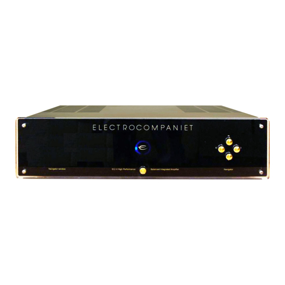
- Page 4 Remote control Diagram 3, page 15 Input selector CD, TUNER, TAPE, DVD, VCR, HT (AUX.) Mute on / off Volume up Volume down Front panel Diagram 2, page 15 The main switch is located in the center of the lower part of the front panel. In daily operation, switch off the ECI 4 by using the MUTE button on the remote control.
- Page 5 Replacing a blown main fuse Diagram 5, page 15 The main fuse is located in a small drawer inside the AC inlet of the unit. If, for some reason the fuse is blown, turn the unit off, and remove the AC cord from the AC inlet. Open the drawer with a small screwdriver and remove the blown fuse.
- Page 6 Technical specifications ECI 4: The following technical data where measured on randomized test objects and are typical data. All measurements are made at 120V / 240V // 50Hz / 60Hz Clipping point of the amplifier is set to a level where total harmonic distortion (THD) is 0.2 %. Preamplifier section Nominal input impedance ........
- Page 7 If the ECI 4 has been switched off, allow two hours of warm-up to optimal sonic performance. Due to high class A operation in all Electrocompaniet designs, it is nor- mal for the ECI 4 to feel warm. Proper ventilation is important. The amplifier is fan cooled. It is important that there is at least 3-5 cm (1-2inches) of air on the left side of the amplifier and 5-8 cm (2-3 inches) above.
- Page 8 Innpakningen er laget for best mulig å unngå skader på produktet under trans- port. Pakk ut apparatet forsiktig. Spar på innpakningen for senere bruk. Eskens innhold 1 stk Electrocompaniet ECI 4 integrert forsterker 1 stk Nettledning 1 stk Reservesikring (ligger i sikringsskuffen bak på apparatet.)
- Page 9 Balansert XLR Du kan bare gå balansert om du har en signalkilde med balanserte utganger. Bruk en signalkabel med jord på pinne 1, pluss på pinne 2 og minus på pinne 3. Om du skal bruke den balanserte inngangen med en single kilde, må du koble i mellom en overgangsplugg (ECP5XLR).
- Page 10 Fjernkontroll Diagram 3 side 15 Inngangsvelger: CD, TUNER, TAPE, DVD, VCR og HT (AUX) Mute av / på Lydstyrke opp Lydstyrke ned Front panel Diagram 2 side 15 Hovedstrømbryter finner du i senter av fronten. Ved daglig bruk kan du skru ECI 4 av ved å...
- Page 11 Skifte av ødelagt nett sikring Diagram 5 side 15 Hovedsikringen finner du i en liten skuff rett under nettinntaket. Om denne sikringen skulle ryke kan du skru av apparatet og fjerne nettledningen. Åpne skuffen med en liten skrutrek- ker og fjern den ødelagte sikringen. Reservesikringen finnes i en liten holder foran den aktive sikringen.
- Page 12 Tekniske spesifikasjoner Følgende tester er gjort på tilfeldig utvalgte produkter og er typiske data for ECI 4. Alle målinger er gjort ved en nettspenning på 120 / 240 V // 50/60Hz. Klippunktet er satt ved en total harmonisk forvrengning (THD) på 0.2%. For forsterker del Nominal input impedance ..........
- Page 13 -Feilbeskrivelse som forklarer feilsymptomer, problemer og hvordan det har oppstått. -Send ECI 4 i original innpakning for å forhindre skader under transport. Electrocompaniet vil ikke dekke skader som har oppstått under transport. Ønsker du mer informasjon om ECI 4 eller har spørsmål angående service er det bare å ta...
- Page 14 Diagram 1...


Need help?
Do you have a question about the ECI4 and is the answer not in the manual?
Questions and answers