
Related Manuals for A&D SV-1A


Summary of Contents for A&D SV-1A
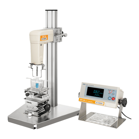
- Page 1 SV-A series -Stand Type- SV-H series -Portable Type- Vibro Viscometer INSTRUCTION MANUAL 1WMPD4001459A...
- Page 2 © 2008 A&D Company Ltd. All rights reserved. No part of this publication may be reproduced, transmitted, transcribed, or translated into any language in any form by any means without the written permission of A&D Company Ltd. The contents of this manual and the specifications of the instrument covered by this manual are subject to change for improvement without notice.
-
Page 3: Table Of Contents
4. DISPLAY AND KEYS ........................20 4-1 Display.............................. 20 4-2 Keys (For all models)........................21 4-3 Displaying the Viscosity Values ......................22 4-3-1 SV-1A/SV-1H ..........................22 4-3-2 SV-10A/SV-10H ......................... 23 4-3-3 SV-100A/SV-100H ........................23 5. PRECAUTIONS ..........................24 5-1 General Precautions (For all models)....................24 5-2 Precautions for an Acurate Measurment (Only for the SV-H series).......... - Page 4 14-3 When more precise measurement is required: (For all models) ............84 14-4 When the temperature values are not correct (For all models)............. 84 14-5 When water viscosity is to be measured (Only for SV-1A/1H/10A/10H)............84 15. ERROR DISPLAY (FOR ALL MODELS) ..................85 16.
-
Page 5: Introduction
1. INTRODUCTION This manual describes how the SV-A/SV-H series viscometer works and how to get the most out of it in terms of performance. Read this manual thoroughly before using the viscometer and keep it at hand for future reference. The SV-A series uses a stand. -
Page 7: Features
Refer to "16. SPECIFICATIONS" on page 86. Measurement of a small amount of sample The SV-1A can measure with a 2 mL sample (minimum amount), and the standard X-Y-Z stage can position the sample container easily. When using the accessory items (sold separately), the SV-1H can measure with stability a 2 mL sample (minimum amount). - Page 8 The vibro viscometer and the capillary viscometer and the rotational viscometer are a type of calibration equipment for viscosity measurement by JCSS standard (Japan Calibration Service System). Simplified calibration when measuring the viscosity near 1 mPa⋅s (Only for SV-1A/1H/ 10A/10H) Simplified calibration using purified water is a one-key operation. The SV-1A/1H/10A/10H has a built-in function to measure the temperature of the purified water using the temperature sensor and calculates the viscosity value of the purified water at that temperature.
-
Page 9: Unpacking The Viscometer
Sensor protective Protector Serial number Sensor cover Sensor plate plate Temperature sensor Surface locator plate Temperature sensor Sample cup knob SV-1A SV-10A/SV-100A Right and left direction Table Guides Leveling foot Display knob Back and forth Connection direction Main unit cable jack... - Page 10 Accessories for SV-1A Square glass sample cup Connection cable (1 pc) AC adapter (1 pc) AC adapter label ( 10 mm x10 mm x 45 mm ) Can be used for optical measuring devices See the note below. Sample cup (Lid attached)
- Page 11 Accessories for SV-10A / SV-100A Connection cable (1 pc) AC adapter (1 pc) AC adapter label Note Please confirm that the AC adapter type is correct for your local voltage and receptacle type. Small sample cup cover Small sample cup Sample cup ( Polycarbonate, 5 pcs) ( Polycarbonate, Capacity: 10 mL,...
- Page 12 (2 pcs) [For 13ml] (1 pc) Sample cup Sample cup [45ml] (5 pcs) [45ml ] (5 pcs) Square glass sample cup (2 pcs) Sample cup stand (1 pc) * Transparent-3 pcs, Black-2 pcs SV-10A / SV-100A SV-1A...
- Page 13 (Confirm the direction of the X-Y-Z stage’s knobs.) Install from forward Install the protector on the sensor unit of the Sensor unit Example: SV-1A SV-1A/SV-10A/ SV-100A. Insert the protector’s rotational axis into the sensor unit’s hole. Rotational...
- Page 14 Lever Raise the lever and install the sensor unit along the guide channels of the supporting post’s sides. At an appropriate height, secure the sensor unit Serial number to the supporting post by lowering the lever. Guide channel Handle the sensor plates with care.
-
Page 15: Part Names For The Sv-H Series (Portable Type)
2-2 Part names for the SV-H series (Portable type) Handle SV-1H SV-10H/SV-100H Sensor unit Sensor plate Serial Sensor number plate Protector Surface Temperature Temperature Main locator plate sensor sensor unit Sensor protective cover Connection Display RS-232C serial interface Keys AC adapter jack Serial number Display unit Reference card... - Page 16 Unpacking / Assembling Note: When assembling, handle the sensor plates with care. 1 Unpack the parts from the carrying case. Connection cable Display Instruction manual AC adapter Knobs for securing the display Stand Sensor unit Handle the sensor plates Protector with care.
- Page 17 4 Confirm that the stand’s mounting holes and the display’s mounting holes match up. Secure both Knob for securing the display sides of the display with the knobs. Display Knob for securing the display Insert the AC adapter plug into the AC adapter Serial number jack located on the rear side of the display unit.
-
Page 18: Changing Type
3. CHANGING TYPE 3-1 Changing from SV-A (Stand type) to SV-H (Portable type) In the case that you have purchased an SV-A series (stand type), and you need to use it as a portable type, make the following changes. Screws Note: When removing or tightening the screws, Screwdriver provided with the viscometer... -
Page 19: Changing From Sv-H (Portable Type) To Sv-A (Stand Type)
Sample cup set (10 mL/13 mL/45 mL) - AX-SV-55 Sample cup set (2 mL) Only for SV-1A/SV-1H Note: When removing or tightening the screws located on the rear side of the sensor unit’s handle, use the screwdriver that is provided with the viscometer. - Page 20 Remove the attachment screw from the X-Y-Z stage base. Install the X-Y-Z stage along the guide Screw ribs from forward of the base. Secure the X-Y-Z stage using the screw removed. (Confirm the direction of the X-Y-Z stage’s knobs.) Install from forward 3 Remove the four screws from the rear side of the sensor unit’s handle.
- Page 21 5 Insert the AC adapter plug into the AC adapter Display unit jack located on the rear side of the display unit. rear side Insert the other end of the AC adapter plug into an electrical outlet. AC adapter cable 6 Press the ON:OFF key to turn the power on.
-
Page 22: Display And Keys
4. DISPLAY AND KEYS 4-1 Display Name Description Standby mode Displays [- - - - -]. Displays the viscosity value in real Measurement mode Viscosity display time. Freezes the display of the viscosity Data hold mode value. Viscosity units Displays the unit of viscosity. Standby mode Displays the temperature value in real time. -
Page 23: Keys (For All Models)
4-2 Keys (For all models) Description Turns the power on and off. ON:OFF When the power is turned on, the viscometer enters the standby Power mode ( [- - - - -] is displayed.) Start a measurement. (The processing indicator blinks.) START Displays the viscosity and temperature values in real time during Start... -
Page 24: Displaying The Viscosity Values
The viscosity values are displayed as below, depending on the unit selected and the viscosity range. The correlation of the units are as follows: 1 mPa⋅s = 0.001 Pa⋅s = 1 cP =0.01 P 4-3-1 SV-1A/SV-1H Use the MODE key to switch between mPa⋅s (Millipascal second) and Pa⋅s (Pascal second), or between cP (Centipoise) and P (Poise). -
Page 25: Sv-10A/Sv-10H
4-3-2 SV-10A/SV-10H Use the MODE key to switch between mPa⋅s (Millipascal second) and Pa⋅s (Pascal second), or between cP (Centipoise) and P (Poise). The unit selected at the factory before shipment is mPa⋅s. When the viscosity unit is mPa⋅s or Pa⋅s: Viscosity Unit selected measured... -
Page 26: Precautions
5. PRECAUTIONS To get the optimum performance from the viscometer and acquire accurate measurement data, note the following: 5-1 General Precautions (For all models) For accurate measurement, use care with the following conditions. Install the viscometer in an environment where the temperature and humidity are not excessive. The best operating temperature is 25°C±2°C at 45-60% relative humidity. -
Page 27: During Use (For All Models)
5-3 During Use (For all models) The SV-A/SV-H series viscometer, designed for very accurate measurement, is sensitive to vibration or shock during transportation, as that may cause a display value error. Before measurement, calibrate the viscometer using the sample cup that will be used for measurement. To level the surface of the sample, adjust the leveling feet. -
Page 28: After Use (For All Models)
Clean the sensor plates carefully to avoid bending them. The sensor plates and the temperature sensor are made of titanium. How to clean the sensor plates and temperature sensor SV-1A/SH-1H Sensor plate Temperature sensor Hold the sensor plates with folded tissue paper. -
Page 29: Measuring The Absolute Value Of Viscosity (For All Models)
5-5 Measuring the Absolute Value of Viscosity (For all models) The SV-A/SV-H Series Sine-wave Vibro Viscometer, as a measuring principle, detects the product of viscosity and density. Displayed viscosity value = Viscosity × Density ⋅ ⋅ ⋅ ⋅ ⋅ [1] While the displayed value has a unit of mPa⋅s, it indicates the product of viscosity and density. -
Page 30: At Calibration
5-5-2 At Calibration When calibrating, enter the product of the absolute viscosity value and the density of the standard viscosity fluid used for calibration, as a correction value. The standard viscosity fluid has the calculation sheet of kinetic viscosity and viscosity at various temperatures attached. -
Page 31: Measurement
* Vibration or shock during transportation may cause a display value error. Before measurement, calibrate the viscometer using the sample cup that will be used for measurement. For calibration with purified water, refer to “8-2-3 Simplified Calibration Using Purified Water”. (Only for SV-1A/10A) Model: SV-1A... - Page 32 Sensor protective 7 Turn the knob (Height direction) so as to cover adjust the sample surface to the center of Protector the narrow part of the sensor plates. Sample Confirm that the sample surface is between surface the upper and lower triangular marks. adjustment position Note...
- Page 33 6 Confirm that the positioning of the sensor plates is in center of the sample cup by adjusting the X-Y-Z stage. Surface 7 Turn the knob (Height direction) so locator plate Sensor protective as to adjust the sample surface to (Shaded portion) cover the center of the narrow part of the...
-
Page 34: Basic Measurement Procedure (For The Sv-A Series)
6-2 Basic Measurement Procedure (For the SV-A series) Below is an example of the SV-10A at shipment. 1 With the power turned off, press the ON:OFF key. When the display is in the standby mode, press the START key. *1 After about 15 seconds, the measurement values are displayed. -
Page 35: Basic Measurement Procedure (For The Sv-H Series)
6-3 Basic Measurement Procedure (For the SV-H series) Beaker Pour the sample into the beaker (500ml) etc. Sample With the power turned off, press the ON:OFF key. When the display is in the standby mode, the SV-H can measure. (Standby mode) Hold the SV-H handle firmly in your hand. - Page 36 - With SV-10H/100H, use the surface locator plate as a guide. The surface locator plate has been secured in position so that the tip of the surface locator plate comes into contact with the sample surface. Surface locator plate Sensor Sensor protective (Shaded portion)
- Page 37 Below is an example of the SV-10H at shipment. 5 After measurement, the buzzer sounds and the displayed value blinks, then holds. Note When the values do not stabilize because of hand movement, set the condition function that levels the large variation in digits (refer to page 54) and the (Standby mode) function that do not display the large variation in digits...
-
Page 38: Changing Units (For All Models)
Use the MODE key to change units. Each time the MODE key is pressed, units are switched as below: Note that the unit of temperature is fixed in the function setting. SV-1A/SV-1H/ SV-10A/SV-10H In the function setting, mPa⋅s or Pa⋅s is selected:... -
Page 39: Using The Water Jacket
10 mL・13 mL・45 mL) or option AX-SV-55 (Cup set, sold separately, capacity: 2 mL, only for the SV-1A/ SV-1H). At this time, use the optional AX-SV-51 stand set (sold separately) if necessary. If you use the optional AX-SV-53-EX software set (sold separately), you can easily understand the graphing data and sample characteristics in real time. -
Page 40: Installation
7-2. Installation With the SV-1A, as the viscometer, the sample cup holder and the sample cup (capacity: 2 mL) provided or the glass sample cup (capacity: 2 mL) also provided, is used. With the SV-10A/100A, as the viscometer, the small sample cup (capacity: 10 mL) provided or the glass sample cup (capacity: 13 mL) also provided, is used. - Page 41 Model: SV-1A Insert the sample cup into the sample cup holder, ant then into the water jacket indicated as 3. When the specific gravity of the sample liquid is small and the sample cup floats, secure lightly the front side of the cup to the water jacket using the screw provided.
-
Page 42: How To Use
Be sure to adjust the sample surface to the center of the narrow part of the sensor plates. Surface Sensor locator plate Sensor protective protective (Shaded portion) cover cover SV-10A/SV-100A Sample Sample surface surface adjustment adjustmen Sample position t position Sample surface surface SV-1A SV-10A/SV-100A... -
Page 43: Measuring The Absolute Value Of Viscosity Using The Small Sample Cup
7-4. Measuring the Absolute Value of Viscosity Using the Small Sample Cup The SV-10A/100A has been calibrated using the accessory sample cup (45 mL) when shipped. The distance between the inner wall and the sensor plates when the accessory sample cup is used, differs from the distance when the small sample cup (10 mL) is used. -
Page 44: Viscosity Calibration (For All Models)
When measuring the viscosity near 1 mPa⋅s, simplified calibration using purified water, which is a one-key operation, is available. The SV-1A/1H/10A/10H/ has a built-in function to perform an automatic temperature compensation on the viscosity value, based on the temperature of the purified water used. -
Page 45: Notes On Viscosity Calibration (For All Models)
Be sure to adjust the sample surface to the center of the narrow part of the sensor plates. Otherwise, a measurement error may occur. In the calibration mode, the unit of viscosity for the SV-1A/1H/10A/10H is mPa⋅s, the unit of viscosity for the SV-100A/100H is Pa⋅s. The unit of temperature is fixed to °C. -
Page 46: Calibration Procedure (For All Models)
8-2 Calibration Procedure (For all models) Note As to the correction value used for one-point calibration and two-point calibration, enter the product of the absolute viscosity value and the density of the standard viscosity fluid. For details, refer to "5-5-2 At Calibration". After calibration, check the values, comparing the product described above with the displayed value. -
Page 47: One-Point Calibration
8-2-1 One-point Calibration Below is an example of the SV-10H. In the standby mode, press and hold HOLD enter (Standby mode) calibration mode. " Cal " appears. Select one-point calibration (Cal-1) Press and hold and press the PRINT key to confirm. The standby mode of the one- calibration mode appears. -
Page 48: Two-Point Calibration
8-2-2 Two-point Calibration Below is an example of the SV-10H. In the standby mode, press and hold HOLD enter calibration mode. " Cal " appears. Select two-point calibration (Cal-2) and press the PRINT key to confirm. The standby mode of the two- calibration mode appears. - Page 49 When the measurement of the first point has completed, clean the sensor plates, temperature sensor and protector and prepare the second standard viscosity fluid. From the previous page Set standard viscosity fluid 10 Place the second standard viscosity fluid in the sample cup.
-
Page 50: Simplified Calibration Using Purified Water (Sv-1A/1H/10A/10H)
8-2-3 Simplified Calibration Using Purified Water (SV-1A/1H/10A/10H) Place the purified water in the sample cup. Press the START key to measure the purified water. Confirm that the viscosity and temperature values are stabilized. Press and hold the START key. theoretical... - Page 51 Reference data: Theoretical viscosity value (Viscosity × Density) of the purified water at various temperatures Viscosity × Density (mPa・s) Temperature (°C) 10.0 1.31 11.0 1.27 12.0 1.24 13.0 1.20 14.0 1.17 15.0 1.14 16.0 1.11 17.0 1.08 18.0 1.05 19.0 1.03 20.0 1.00...
-
Page 52: Function Setting (For All Models)
9. FUNCTION SETTING (FOR ALL MODELS) The viscometer, by selecting functions to be used in the function setting, can specify the performance appropriate to the usage. Each function is assigned parameters. The performance of a function is specified by changing the parameter. - Page 53 Example of the function setting procedure To change the setting of "Unit upon power-on (Unit)" to the viscosity: cP (Centipoise) and the temperature: °C (Celsius). In the standby mode, press and hold the MODE key to enter the function setting mode. " 5vtyp " appears.
-
Page 54: Details Of The Function Items (For All Models)
Follows the viscosity changes slowly. (Stable values) • Unit MmPa⋅s • Unit upon power-on Pa⋅s °C Factory setting: Temper- Viscosity SV-1A/1H/10A/10H=0 ature mmPa⋅s SV-100A/100H=1 Pa⋅s °F • With "Comma" selected, the separator for CSV format will Decimal point Comma be ";" (semicolon). - Page 55 When setting the auto hold S5t-b Stable when within±5% function, it can be set. • Stability band width (H-fnc 1) Stable when within±15% Hld-t 15 second When setting timer • mode function, it can be Hold time 30 second set.(H-fnc 2) 45 second 1 minutes •...
-
Page 56: Description Of Items (For All Models)
Consider the ambient conditions slowly. of the installation site. (Stable values) Unit Upon Power-on (Unit) The units of viscosity and temperature displayed when the power is turned on are specified. SV-1A/1H/10A/10H Parameter Settings Description mmPa⋅s • (Millipascal second) Pa⋅s... - Page 57 Parameter Settings Description Each time the MODE key is pressed, the viscosity unit is switched. SV-1A / 1H / 10A / 10H: mPa⋅s ⇔ Pa⋅s, cP ⇔ P Switches the viscosity SV-100A / 100H : Pa⋅s ⇔ P • units.
- Page 58 The viscosity value and the temperature are output using the internal resolution.*3 The relation between the measuring unit and the internal resolution is as follows: Viscosity Temperature Model °C °F mmPa・s Pa・s SV-1A/SV-1H 0.01 0.0001 0.01 0.0001 Internal SV-10A/SV-10H 0.01 0.01 resolution SV-100A 0.01...
- Page 59 Other Output (5-ed) Parameter Settings Description No output With D.P. format selected, whether or not to add remarks, Outputs remarks. Device ID information or signature to the measurement data Outputs remarks, can be selected. • Device ID information For examples of output format, refer to "9-4 Data Output and signature.
- Page 60 Comparator (Cp) The results of the comparison are indicated by the sound. (It is necessary to set : bep - , bep-, bep - ) To compare, use: Upper limit value and lower limit value Input method: Digital input Setting example Selecting a comparator mode 1 Press and hold the MODE key until 5vtyp of the function table is displayed.
- Page 61 Setting the ID number In the standby mode, press and hold the MODE key to enter the function setting mode. " 5vtyp " appears. (Standby mode) Press and hold Press the MODE key to select " id ". Press the PRINT key to enter the ID number setting mode.
- Page 62 Initialization (Clr) Restores the following data to the default setting. Function setting (Setting of “5vtyp” is not returned by this operation) Calibration data After initialization, check the viscosity value and perform calibration as necessary. (Refer to 8. VISCOSITY CALIBRATION"). In the standby mode, press and hold the (Standby mode) MODE key to enter the function setting mode.
- Page 63 Date/Time (Cladj) The upper two digits of the year are not displayed. For example, the year 2007 is displayed as "07". The time is set using the 24-hour system. Do not enter a non-existing date and time. Set the order of the date, the date and time as follows: (Example: To change April 5, 2006, 11:22:33 to June 8, 2007, 12:34:00) In the standby mode, press and hold the MODE (Standby mode)
- Page 64 Changing the date The date is changed in the selected displaying order. The following is an example when the order of " y " (Year), " m " (Month) and " d " (Day) is selected. Press the MODE key to select the setting value of "...
- Page 65 Changing the time From the previous page 13 The current time is displayed. Press the MODE key to display the current date. To current date display (Go to page 61) (Current time display) 14 Press the PRINT key to select the setting value of the hour.
-
Page 66: Data Output Format Examples (For All Models)
9-4 Data Output Format Examples (For all models) 9-4-1 A&D Standard Format Used with the printer MODE 1 or MODE 2 when the optional compact printer AD-8121B is connected. Only the viscosity value is output. SV-1A/SV-1H output format example Viscosity Display Output format... - Page 67 SV-10A/SV-10H output format example Viscosity Display Output format Remarks unit LLLLL mPa・s Below measuring range error OL,-99999999mPs 0.30mPa・s ST,+00000.30mPs 10.0 mPa・s The digit of 0.01mPa⋅s is always zero. ST,+00010.00mPs mPa・s The digits of 0.01mPa⋅s and ST,+00100.00mPs 0.1mPa⋅s are always zero. MmPa・s 1.00 Pa・s For 1000mPa⋅s or greater, the...
-
Page 68: Format
SV-100A/SV-100H output format example Viscosity Display Output format Remarks unit OL,-99999999Pas Below measuring range error Pa・s ST,+00001.00Pas 1.00 Pa・s mmPa・s ST,+00010.00Pas 10.0 Pa・s The digit of 0.01Pa⋅s is always zero. OL,+99999999Pas Above measuring range error Pa・s OL,-99999999 Below measuring range error ST,+000010.0 10.0 P ST,+000100.0... -
Page 69: Csv Format
With CSV format selected, the viscosity value and the temperature are output using the internal resolution. The relation between the measuring unit and the internal resolution is as follows: Viscosity Temperature Model °C °F mmPa・s Pa・s SV-1A/SV-1H 0.01 0.0001 0.01 0.0001 Internal SV-10A/SV-10H 0.01 0.01 resolution SV-100A 0.01... - Page 70 √ 5-td Date/time The output data are 52 characters long excluding the Device √ 5-ed terminator. ID number SV-1A/SV-1H output format example Viscosity Display Output format example Remarks Temper- ature Zeroes are output for LLLLLmPa・s LAB-12,2003/03/19,12:34:56,+025.67,C,+00000.00,mPa s below measuring range error.
- Page 71 SV-10A/SV-10H output format example Viscosity Display Output format example Remarks Temper- ature Zeroes are output for LLLLLmPa・s LAB-12,2003/03/19,12:34:56,+025.67,C,+00000.00,mPa s below measuring range error. 0.30 mPa・s LAB-12,2003/03/19,12:34:56,+025.67,C,+00000.30,mPa s 10.0 mPa・s LAB-12,2003/03/19,12:34:56,+025.67,C,+00010.00,mPa s mmPa・s mPa・s LAB-12,2003/03/19,12:34:56,+025.67,C,+00100.00,mPa s 1.00 Pa・s For 1000 mPa⋅s or LAB-12,2003/03/19,12:34:56,+025.67,C,+01000.00,mPa s °C greater, the displayed...
- Page 72 (√=Output Blank=No output) The output data are 46 characters long excluding the √ 5-td Date/time terminator. Device 5-ed ID number SV-1A/SV-1H/SV-10A/SV-10H output format example Viscosity / Temperature Display Output format example °C MmPa⋅s / 1.23 mPa⋅s ,2003/03/19,12:34:56,+025.67,C,+00001.23,mPa s : Space (ASC 20h)
-
Page 73: Rsvisco Format
SV-1A/SV-1H/SV-10A/SV-10H output format example Viscosity / Temperature Display Output format example °C 1.23 mPa⋅s mmPa⋅s / ,,,+025.67,C,+00001.23,mPa s : Space (ASC 20h) SV-100A/100H output format example Viscosity / Temperature Display Output format example °C Pa⋅s / 1.23 Pa⋅s ,,,+025.67,C,+00001.23, Pa s... - Page 74 SV-1A/SV-1H output format example Viscosity Display Output format example Remarks Temper- ature Zeroes are output for below measuring +00000.00,mPa s,+025.67,C LLLLL mPa・s range error. +00000.30,mPa s,+025.67,C 0.30 mPa・s mmPa・s +00010.00,mPa s,+025.67,C 10.0 mPa・s +00100.00,mPa s,+025.67,C mPa・s °C For 1000 mPa⋅s or greater, the displayed unit +01000.00,mPa s,+025.67,C...
- Page 75 SV-10A/SV-10H output format example Viscosity Display Output format example Remarks Temper- ature Zeroes are output for below measuring +00000.00,mPa s,+025.67,C LLLLL mPa・s range error. +00000.30,mPa s,+025.67,C 0.30 mPa・s MmPa・s +00010.00,mPa s,+025.67,C 10.0 mPa・s +00100.00,mPa s,+025.67,C mPa・s °C For 1000 mPa⋅s or greater, the displayed unit +01000.00,mPa s,+025.67,C 1.00 Pa・s is Pa⋅s, but the output unit remains mPa⋅s.
-
Page 76: Connection To A Personal Computer
10.CONNECTION TO A PERSONAL COMPUTER 10-1 Introduction If connecting the SV-A / SV-H series to a personal computer using the Windows communication tools WinCT-Viscosity (CD-ROM), the measurement data can be imported into the personal computer. The graphing program RsVisco that is contained in the Windows communication tools WinCT-Viscosity has following features. -
Page 77: Connection To A Personal Computer
10-3 Connection to a personal computer In a case where the personal computer has a COM port The SV-A / SV-H series can connect to a personal computer using the RS-232C cable. RS-232C Display rear side RS-232C cable Personal computer In a case where the personal computer does not have a COM port (Example: notebook type etc) By using the standard Serial-USB converter provided, a personal computer can increase the number of COM ports available. -
Page 78: Configuration Of The Com Port
10-4 Configuration of the COM port When connecting the SV-A / SV-H series to a personal computer, confirm that the COM port setting match up. (1) Configuring of the COM port 1 Click the START bottom → the“Setting” → the“Control panel”. 2 Double-click the“System”... -
Page 79: Controlling The Measurement Using A Personal Computer
10-5 Controlling the measurement using a personal computer (In case of the graphing software“RsVisco”) 1 Refer to “6. MEASUREMENT”, prepare the measurement. 2 Start the graphing software“RsVisco”. 3 Confirm that the COM port of the“RsVisco” is set properly. 4 Click the START button of the“RsVisco” to start the measurement. 5 If you want to finish the measurement, click the START button of the“RsVisco”. -
Page 80: Connection To A Printer (For All Models)
11. CONNECTION TO A PRINTER (FOR ALL MODELS) The viscometer can be connected to the optional compact printer AD-8121B using the standard RS-232C interface and the measurement results can be printed. The statistical calculation data of the results and the changes in the viscosity value per a certain time can be printed using the function of the AD-8121B. -
Page 81: Rs-232C Serial Interface (For All Models)
12. RS-232C SERIAL INTERFACE (FOR ALL MODELS) RS-232C Serial Interface Transmission system EIA RS-232C Transmission form Asynchronous, bi-directional, half duplex Data format Baud rate 2400 bps Data bits 7 bits Parity EVEN Stop bit 1 bit Code ASCII Terminator CR LF (CR: 0Dh, LF: 0Ah) RS-232C Bit format -5 V to -15 V... -
Page 82: Command List (For All Models)
13. COMMAND LIST (FOR ALL MODELS) The viscometer can be controlled by the following commands from the computer. Add a terminator ( 0Dh、0Ah ) to each command. Command Description Outputs the current data. Outputs data continuously Stops data output by SIR command. Outputs the data during measurement. -
Page 83: Troubleshooting (For All Models)
Install the viscometer away from the electrical or magnetic noise sources With SV-1A/SV-1H, if the sensor plate touches the inner wall of the 2 mL cup, the displayed value will not stabilize. Adjust the spacing between the sensor plate and the inner wall of the 2 mL cup. - Page 84 Pull the sensor protective cover in the direction indicated as 2 to remove. Note When removing the sensor protective cover, it may touch the sensor plates and the temperature sensor. Use much care not to damage them. (Sensor unit underside view) (Example: SV-1A/SV-1H)
-
Page 85: When Measurement Values Are Not Correct (For All Models)
14-2 When measurement values are not correct (For all models) Is the viscometer in the data hold mode? To release the data hold mode, press the HOLD key. The processing indicator blinks while a measurement is performed. Has the sample surface been adjusted to the center of the narrow part of the sensor plates? Adjust the table height by turning the knob so that the center of the narrow part of the sensor plates is on the sample surface. -
Page 86: When More Precise Measurement Is Required: (For All Models)
With the SV-A series, refer to page 12. With the SV-H series, refer to pages 14-15. 14-5 When water viscosity is to be measured (Only for SV-1A/1H/10A/10H) When tap water is poured into the sample cup directly and is measured, bubbles are generated on the sensor plates due to the difference in pressure and temperature and the viscosity may increase gradually. -
Page 87: Error Display (For All Models)
Description Above measuring range error The viscosity value exceeds the upper limit of the viscosity measuring range (SV-1A/SV-1H: 1.19 Pa⋅s, SV-10A/SV-1H: 11.99 Pa⋅s, SV-100A/SV-100H: 119.9 Pa⋅s). The viscosity of the sample can not be measured. This error may occur when the display unit is not connected to the main unit. -
Page 88: Specifications
16. SPECIFICATIONS Measurement method SV-1A/SV-1H SV-10A/SV-10H SV-100A/SV-100H Sine-wave Vibro Viscometer using the Tuning-fork Vibration method Measurement method Vibration frequency 30 Hz 1 to 100 Pa⋅s 0.3 to 10000 mPa⋅s Viscosity measuring range 0.3 to 1000 mPa⋅s (1000 to 100000 mPa⋅s) - Page 89 For the SV-1A/1H when a sample cup of 2 mL is used. For the SV-10A/10H and SV-100A/100H when a sample cup of 45 mL is used. Repetitive measurement with the sensor plates remaining in the sample The value after calibration using a standard viscosity fluid at a temperature range between 20°C and 30°C with no condensation.
-
Page 90: Optional Accessories
17. OPTIONAL ACCESSORIES List of Optional Accessories (sold separately) Available ( ) Model Name 1A/1H 10A/10H 100A/100H AX-SV-31-2.5 Standard viscosity fluid (JS2.5) AX-SV-31-5 Standard viscosity fluid (JS5) AX-SV-31-10 Standard viscosity fluid (JS10) AX-SV-31-20 Standard viscosity fluid (JS20) AX-SV-31-50 Standard viscosity fluid (JS50) Capacity: 500 mL, AX-SV-31-100 Standard viscosity fluid (JS100) - Page 91 Available ( ) Model Name 1A/1H 10A/10H 100A/100H AX-SV-55 Cup set(Capacity: 2 mL) (Water jacket attached) ( Used with the all model of the SV series) Sample cup (Capacity: 45 mL) 5 pcs Sample cup (Capacity: 2 mL, Lid attached) 10 pcs Sample cup holder (For 2 mL capacity) 5 pcs Sample cup stand (For 2 mL capacity) 1 pc...
- Page 92 AX-SV-36 Positioning Stopper • Used to fix the position of the sensor unit and the sensor plates so that positioning the sensor plates and the sample surface is not required each time a measurement is performed in a repetitive test. See below for how to attach the positioning stopper.
- Page 93 AX-SV-37 Water Jacket Assembly • Used, in combination with a commercially available constant temperature bath for heating medium circulation, to maintain the sample temperature constant or to measure the viscosity while changing the sample temperature. • The glass sample cup sold separately can also be used.
- Page 94 X-Y-Z stage 1 pc Sample cup • Used when a small amount of sample (2 mL) will be (Lid attached) measured. (Only for SV-1A/SV-1H) X-Y-Z stage - Consists of : Sample cup (Capacity: 2 mL) 1 pc Sample cup holder...
- Page 95 AX-SV-52 X-Y-Z Stage X-Y-Z stage • Used to support and adjust the sample cup position. - Consists of : X-Y-Z stage 1 pc AX-SV-53-EX Software Set • Used while acquiring the viscosity data with a personal computer. - Consists of : RS232C straight WinCT-Viscosity 1 pc...
- Page 96 AX-SV-54 Cup Set (10 mL / 13 mL / 45 mL) (Use the AX-SV-51 Stand Set if necessary.) • Used when a small amount of sample will be measured. - Consists of : Sample cup (45 mL) 5 pcs Small sample cup (10 mL) 5 pcs Small sample cup cover 5 pcs...
- Page 97 Only for SV-1A/SV-1H (When using this option, use the AX-SV-51 Stand Set) Sample cup AX-SV-55 Cup Set (2 mL) • Sample cup set (Only for SV-1A/SV-1H) Used when a small amount of sample (2 mL) will be Sample cup holder measured.
- Page 98 Sample cup stand 2 pcs Sample cup stand AX-SV-58 Sample Cup (2 mL) • Sample cup set (Only for SV-1A/SV-1H) Used when a small amount of sample (2 mL) will be measured. - Consists of : Sample cup Sample cup (2 mL)
- Page 99 AX-SV-60 Square glass sample Cup (10 mm x 10 mm x 45 mm) • Can be used for optical measuring devices such as a spectrophotometer. - Consists of : Square glass sample cup 2 pcs (Pyrex® glass) Square glass sample cup Square lid 2 pcs (Lid attached)
-
Page 100: External Dimensions
18. EXTERNAL DIMENSIONS SV-1H / SV-10H / SV-100H Display unit (For all models) Sensor unit (Handle*) * The SV-A series external dimensions are as follows when the handle is used. The connection cable is 1.5m long. Unit: mm... - Page 101 SV-1A / SV-10A / SV-100A Stand unit* * The SV-H series external dimensions are as follows when the AX-SV-51 (stand set) is used. 11.5 *A=Sensor plates lowest position 3.5 mm (With protector used, no table) *B=Sensor plates highest position 268 mm...
-
Page 102: Detailed View Of The Sensor Unit
Detailed View of the Sensor Unit φ SV-1A/SV-1H SV-10A/SV-10H SV-100A/SV-100H *D=Distance from the sensor protective cover Unit: mm...
Need help?
Do you have a question about the SV-1A and is the answer not in the manual?
Questions and answers