Table of Contents
Advertisement
Quick Links
–{'Ì‚ÌŽ÷Ž‰ƒR•[ƒeƒBƒ"ƒO•"‚𕕂‚¯‚È‚¢‚悤Žæˆµ‚Á‚Ä‚-‚¾‚³‚¢•B
‚Ƀ••[ƒhƒZƒ‹‚ɉߕ‰‰×‚ª‚©‚©‚ç‚È‚¢‚悤‚²'•ˆÓ‚-‚¾‚³‚¢•B
‚R•| 1 ƒx•[ƒX‚Ö‚Ì•Ý'u
•i‚P•j ƒx•[ƒX‚É‚Í•„•«‚Ì—L‚é‚à‚Ì‚ðŽg—p‚µ‚Ä‚-‚¾‚³‚¢
‹È‚ª‚Á‚½‚è‚·‚é‚Æ•¸"x‚Ɉ«‰e‹¿‚ð‹y‚Ú‚µ‚Ü‚·
•i‚Q•j ƒx•[ƒX‚ƃ••[ƒhƒZƒ‹‚ÌŠÔ‚É•A
•i‚R•j ƒ••[ƒhƒZƒ‹Žæ•t–Ê•A
‹y‚уXƒy•[ƒT‚Í•\–Ê'e‚³
⢥B
•i‚S•j ƒx•[ƒX‚Ö‚ÌŽæ•t‚¯‚É‚Í•A
ƒnƒCƒeƒ"ƒVƒ‡ƒ"˜ZŠpƒ{ƒ‹ƒg‚ðŽg—p‚µ‚Ä‚-‚¾‚³‚¢
•i'áˆø'£‹-"x•j
‚Í‹-"x‚ª•s'«‚µ‚Ü‚·‚Ì‚Å•A
‚Ì •„•§'÷‚ß•t‚¯ƒgƒ‹ƒN‚Í•\•|‚P‚Ì'Ê‚è‚Å‚·
•i‚T•j ƒ••[ƒhƒZƒ‹‚ðŽæ•t‚¯‚é'O‚É•A
‚-‚¾‚³‚¢•B ƒ{ƒ‹ƒg‚ð'÷‚ß•t‚¯‚鎞‚Í•A
•s‚Á‚Ä‚-‚¾‚³‚¢•B
•i•}•|‚PŽQ•Æ•j
‚R•|‚Qƒvƒ‰ƒbƒgƒz•[ƒ€‚ÌŽæ•t‚¯
•i‚P•j ƒ••[ƒhƒZƒ‹‚Ì•«"\‚ð'·ŠúŠÔˆÛŽ•‚·‚邽‚ß‚É•A
•‰‰×‚Í•o—ˆ‚éŒÀ‚蕬‚³‚-‚µ‚Ä‚-‚¾‚³‚¢
•i‚Q•j ƒvƒ‰ƒbƒgƒz•[ƒ€‚ƃ••[ƒhƒZƒ‹‚ÌŠÔ‚É•A
‚³‚¢•B
•i‚R•j ƒ••[ƒhƒZƒ‹Žæ•t–Ê•A
‹y‚уXƒy•[ƒT‚Í•\–Ê'e‚³
⢥B
•i‚S•j ƒvƒ‰ƒbƒgƒz•[ƒ€‚ÌŽæ•t‚¯‚É‚Í•A
‚Ü‚½‚Í•A ƒnƒCƒeƒ"ƒVƒ‡ƒ"˜ZŠpƒ{ƒ‹ƒg‚ðŽg—p‚µ‚Ä‚-‚¾‚³‚¢•B
•i'áˆø'£‹-"x•j
‚Í‹-"x‚ª•s'«‚µ‚Ü‚·‚Ì‚Å•A
‚Ì •„•§'÷‚ß•t‚¯ƒgƒ‹ƒN‚Í•\•|‚P‚Ì'Ê‚è‚Å‚·
•i‚T•j ƒ••[ƒhƒZƒ‹‚ðŽæ•t‚¯‚é'O‚É•A
‚-‚¾‚³‚¢•B ƒ{ƒ‹ƒg‚ð'÷‚ß•t‚¯‚鎞‚̓••[ƒhƒZƒ‹‚É•s—p‚È•‰‰×
‰¡‰×•d"™•j
‚ð‰Á‚¦‚È‚¢‚悤‚É'•ˆÓ‚µ‚Ä‚-‚¾‚³‚¢•B
•i‚U•j ƒvƒ‰ƒbƒgƒz•[ƒ€‚Ì‹–—e•¡–@‚Í•}•|‚P‚ðŽQ•Æ‚µ‚Ä‚-‚¾‚³‚¢•B
ƒz•[ƒ€‚Ì•ÝŒv‚ɂ͉ߕ‰‰×‚ÉŠÖ‚·‚é'•ˆÓŽ–•€‚ðŽQ•Æ‚µ‚Ä‚-‚¾‚³‚¢•B
WM:PD4000328
'•ˆÓ
¡ ƒx•[ƒX‚ªŠÈ'P‚ÉŒX‚¢‚½‚è•A
¡
Œú‚³ 2mm ˆ È•ã‚̃Xƒy•[ƒT‚ð"ü‚ê‚Ä‚-‚¾‚³‚¢•B
25 ƒÊ mRa ˆÈ‰º‚ÉŽd•ã‚°‚Ä‚-‚¾‚³
‹-"x‹æ•ª 10.9'Š"–ˆÈ•ã‚̘ZŠpŒŠ•tƒ{ƒ‹ƒg‚Ü‚½‚Í•A
¡ ˆê"Ê"I‚ÈŽs"̃{ƒ‹ƒg
Žg—p‚µ‚È‚¢‚Å‚-‚¾‚³‚¢
¡
•\•|‚P
Žæ•t–Ê‚É•t'...‚µ‚Ä‚¢‚éƒSƒ~"™‚ð•K‚¸Žæ‚è•œ‚¢‚Ä
ƒ••[ƒhƒZƒ‹‚ÌŒÅ'è'¤‚ð‰Ÿ‚³‚¦‚È‚ª‚ç
ƒvƒ‰ƒbƒgƒz•[ƒ€‚â•—'Ü"™‚É‚æ‚é
¡
Œú‚³ 2mm ˆ È•ã‚̃Xƒy•[ƒT‚ð"ü‚ê‚Ä‚-‚¾
25 ƒÊ mRa ˆÈ‰º‚ÉŽd•ã‚°‚Ä‚-‚¾‚³
‹-"x‹æ•ª 10.9'Š"–ˆÈ•ã‚̘ZŠpŒŠ•tƒ{ƒ‹ƒg
ˆê"Ê"I‚È Ž s"̃{ƒ‹ƒg
Žg—p‚µ‚È‚¢‚Å‚-‚¾‚³‚¢
¡
Žæ•t–Ê‚É•t'...‚µ‚Ä‚¢‚éƒSƒ~"™‚ð•K‚¸Žæ‚è•œ‚¢‚Ä
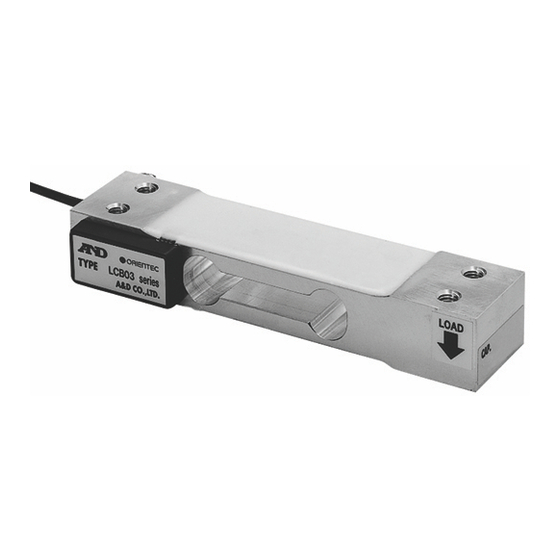
1. INTRODUCTION
The LCB03 series single point beam load cells are compact (130 mm
length, 22 mm height) and low cost, optimum as platforms for from ordi-
nary weighing to platforms for mixing and filling. Being of a single point
design allows for simplified weighing system construction.
To install the load cell properly, the static conditions, as well as dynamic
factors (i.e., shock and vibration) must be considered.
To obtain the best performance from the load cell, read this instruction
manual before installation.
2. SPECIFICATIONS
Rated output ............................................................................... 2mV/V 10%
Maximum safe overload ............................................ 150% of rated capacity
Combined error ........................................................... 0.02% of rated output
Zero balance ................................................................... 5% of rated output
Compensated temperature range ............................................ -10
Maximum excitation voltage ...................................................................... 15V
Input terminal resistance .............................................................. 420
Output terminal resistance ............................................................. 350
Insulation resistance ........................................... 2000M
Temperature effect on zero .............................. 0.023% of rated output/ 10
Temperature effect on span ...................................... 0.014% of LOAD/ 10
Cable thickness/length ................................................................
Maximum loading area ................................................... 300 mm
Maximum moment ......................................... (Rated capacities) X 75 N cm
‚Ü‚½•Ý'uŽž
3. NOTES ON INSTALLATION
Use care not to damage the resin coating of the load cell. When
installing, do not apply excessive load to the load cell.
3-1 INSTALLING ON A BASE
(1) The base should be rigid to prevent it from slanting or curving under
normal operating conditions.
If the base yields, the platform will bend and adversely affect the load
cell.
(2) Insert a spacer of 2 mm or greater between the load cell and the base.
¡ ƒ{ƒ‹ƒg
(3) Use a highly rigid base. The mounting surface for the load cell and the
spacer requires a surface finish of at least 25 mRa (JIS*).
*JIS=Japan Industrial Standard
(4) Use hexagon socket head bolts (tensile strength Class 10.9-JIS or over)
or high-tension hexagon head bolts (tensile strength Class 10.9-JIS or
over) to attach the load cell on the base. Table 1 shows the applicable
clamping torque. Be sure to avoid using ordinary bolts (of a lower tensile
strength) available on the market.
(5) Make sure that the attaching surface is clean and free from foreign matter.
Tighten the bolts while holding the securing end of the load cell.
3-2 ATTACHING THE PLATFORM
(1) The tare and the platform should be as light as possible to prolong the
service life and excellent performance of the load cell.
(2) Insert a spacer with 2 mm or greater between the load cell and the
¡ ƒ{ƒ‹ƒg
platform.
(3) Use a platform fixture with high rigidity. The mounting surface for the
load cell and the spacer requires a surface finish of 25 mRa (JIS*) or
•i‚Ë‚¶‚è‚â•A
less.
(4) Use hexagon socket head bolts (tensile strength Class 10.9-JIS or over)
‚Ü‚½•A
ƒvƒ‰ƒbƒg
or high-tension hexagon head bolts (tensile strength Class 10.9-JIS or
over) to attach the platform fixture to the load cell. Table 1 shows the
applicable clamping torque. Avoid using ordinary bolts (of low tensile
strength) available on the market.
(5) Make sure that the attaching surface is clean and free from foreign matter.
Tighten the bolts while using much care not to apply unnecessary force
(torsion or lateral load) to the load cell.
SINGLE POINT BEAM LOAD CELL
LCB03 Series
NOTE
Table 1
to 40
30
5
or over at 50VDC
3.5 0.4m
300 mm
Advertisement
Table of Contents

Related Manuals for A&D LCB03 Series


Summary of Contents for A&D LCB03 Series
- Page 1 LCB03 Series 1. INTRODUCTION The LCB03 series single point beam load cells are compact (130 mm length, 22 mm height) and low cost, optimum as platforms for from ordi- nary weighing to platforms for mixing and filling. Being of a single point design allows for simplified weighing system construction.
- Page 2 (6)For the allowable dimensions of the platform, see Figure 1. Also, when designing a platform, see the "3-3 OVERLOAD PRECAUTIONS" . 3-3 OVERLOAD PRECAUTIONS (1) Mechanical strength of the load cell When a load is applied to the center of the load cell, a load of less than 150% of the rated capacity will not cause any trouble.
Need help?
Do you have a question about the LCB03 Series and is the answer not in the manual?
Questions and answers