Table of Contents
Advertisement
Advertisement
Table of Contents

Related Manuals for Ariens 921 Series


Summary of Contents for Ariens 921 Series
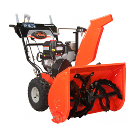
- Page 1 921 Series Sno-Thro ® Owner/Operator Manual Manuel Du Propriétaire/Utilisateur Models 921013 – Deluxe 30 921017 – Deluxe 24 Platinum 921018 – Deluxe 30 Platinum 921019 – Deluxe 24 921020 – Deluxe 30 921022 – Deluxe 28 921023 – Deluxe Track 28 ENGLISH FRANÇAIS...
-
Page 2: Table Of Contents
If used Dealer. Visit your dealer or improperly, this unit could be dangerous and www.ariens.com for a list of cause personal injury or property damage. languages available for your The contents will provide you with safety equipment. -
Page 3: Unauthorized Replacement Parts
6. Fill out a Product Registration Card and Customer Note: If the dealer does not return the card to the Ariens Company or register your product, please fill out, sign, and go to www.ariens.com. return the product registration card to Ariens or go to www.ariens.com. -
Page 4: Safety
SAFETY NOTATIONS WARNING: To avoid injury to NOTE: General reference information for hands and feet, always disengage proper operation and maintenance practices. clutches, shut off engine, and wait IMPORTANT: Specific procedures or for all movement to stop before information required to prevent damage to unclogging or working on snow unit or attachment. -
Page 5: Emission Control System
Emission controls and components can only be adjusted by an OL4010 Ariens Company dealer or an authorized engine manufacturer's service center. Contact your Ariens Company Equipment Wear appropriate hearing Retailer concerning emission controls and protection. - Page 6 ALWAYS remove key and/or wire from spark DO NOT touch unit parts which might be hot plug before assembly, maintenance or from operation. Allow parts to cool before service. Unintentional engine start up can attempting to maintain, adjust or service. cause death or serious injury.
- Page 7 Before cleaning, removing clogs or making Never fill containers inside a vehicle or on a any inspections, repairs, etc.: disengage truck or trailer bed with a plastic liner. Always clutch(es), stop unit and engine, remove key, place containers on the ground away from allow moving parts to stop.
-
Page 8: Assembly
ASSEMBLY 921017, 018 WARNING: AVOID INJURY. Read and understand the entire Safety section before proceeding. WARNING: Dropping or tipping over boxed unit could result in personal injury or damage to unit. PACKAGE CONTENTS 921013, 019, 020, 022, 023 1. Sno-Thro 4. - Page 9 Install Discharge Chute and Discharge Chute Crank (921013, 019, 020, 022, 023) (Figure 7, 8, and 9) 1. Grease underside of discharge chute ring (if not already greased). 2. Remove mounting hardware from auger 1, 2 housing (Figure 7). 3. Install discharge chute over opening in the auger housing.
- Page 10 Install Discharge Chute and 921013, 020, 023 Discharge Chute Rod (921017, 018) (Figure 10, 11 and 12) 1. Grease underside of discharge chute ring (if not already greased). 2. Remove mounting hardware from auger housing (Figure 7). 3. Install discharge chute over opening in the auger housing.
- Page 11 NOTE: After the chute rod has been inserted 11. Replace the gear cover removed in through the hex hole in the control assembly, step 4. placing the unit in the service position (see 12. Orient the chute and pedestal to its most Service Position on page 23) will ease vertical position and tighten pedestal alignment and installation of the hair pin.
- Page 12 Check Function of Dual Handle Check Track Tension Interlock (921023) Without the engine running, press down Check tracking of unit with the differential (engage) both clutch levers. Release locked, and tension of tracks (see Track attachment clutch lever. Attachment clutch Tension Adjustment on page 35).
-
Page 13: Controls And Features
CONTROLS AND FEATURES 1. Attachment Clutch Lever 2. Speed Selector 3. Traction Drive Clutch Lever 4. Remote Wheel Lock (013, 020, 022) SMALL DASH 5. Remote Deflector Control (013, 017, 018, 020, 022) 6. Height Adjuster Trigger (023) 7. Chute Rotation Control (017, 018) LARGE DASH OS7440 Figure 14... - Page 14 1. Skid Shoe 2. Clean-Out Tool 3. Remote Discharge Chute Deflector (013, 017, 018, 020, 022, 023) 4. Manual Discharge Chute Deflector (019) 5. Belt Cover 6. Headlight (013, 017, 018, 020, 022, 023) 7. Auger 8. Auger Gearcase 9. Scraper Blade 10.
- Page 15 1. Oil Drain 921013, 017, 018, 022, 023 2. Fuel Shut-Off Valve 3. Primer Bulb 4. Recoil Starter Handle 5. Throttle (Engine Stop) 6. Choke Control Knob 7. Ignition Key 8. Fuel Tank and Cap 9. Oil Fill/Dipstick 921019, 020 OS7410 Figure 16 OS7415...
-
Page 16: Operation
OPERATION Attachment Clutch - WARNING: AVOID INJURY. Read Right Hand Lever and understand the entire Safety section before proceeding. Squeeze Attachment Clutch Lever against handlebar (1) to engage attachment. WARNING: To avoid injury to hands Release both clutch and feet, always disengage levers (2) to disengage clutches, shut off engine, and wait power and apply brake... - Page 17 Primer Bulb Choke Control Knob Pushing the primer bulb 1.Choke Closed in adds fuel for easier position: chokes off air engine start. Refer to to engine for easier Starting and Shut Off on start. page 21. 2.Choke Open OS7320 position: allows for normal operation.
- Page 18 Snow Clean-Out Tool Manual Discharge Deflector (921019) (Figure 18) (Figure 17) ALWAYS position discharge chute deflector at a safe angle before starting engine. DO WARNING: Hand contact with the NOT throw snow any higher than necessary. rotating impeller is the most 1.
- Page 19 IMPORTANT: DO NOT force frozen chute Wheel Unlocked controls. If frozen, take to warm place until controls are free. Discharge Chute Crank (921013, 019, 020, 022, 023) (Figure 20) IMPORTANT: If chute does not stay in set position, adjust as directed in SERVICE AND ADJUSTMENTS on page 26, or repair before operation.
-
Page 20: Filling Fuel Tank
Scraper Blade FILLING FUEL TANK The scraper blade allows better contact with the surface being cleared. It also prevents WARNING: AVOID INJURY. Read damage to the housing from normal usage. and understand the entire Safety IMPORTANT: DO NOT allow Scraper Blade section before proceeding. - Page 21 4. Check Remote Wheel Lock (921013, 020, 022) 921013, 017, 018, 921019, 020 Squeeze and release the remote wheel lock 022, 023 control to lock the left wheel for better traction when throwing snow or to unlock the left wheel for easier steering. If remote wheel lock does not lock or unlock properly, adjust or repair before operation (see Remote Wheel Lock on page 26).
-
Page 22: Snow Removal
2. Plug extension cord into 120V 3-wire, direction. grounded outlet. 2. Engage Attachment Clutch - Right Hand IMPORTANT: Use only Ariens extension cord Lever. (P/N 02483100) or an equilavent cord that is 3. Engage Traction Drive Clutch - Left rated for a minimum of 13 amps, grounded, Hand Lever. -
Page 23: Traveling And Transport
3. Engage wheel or track drive clutch running. without engaging attachment drive clutch. MAINTENANCE Ariens Dealers will provide any service or Service Position adjustments which may be required to keep your unit operating at peak efficiency. Should engine service be required, contact an Ariens dealer or an authorized engine manufacturer's service center. -
Page 24: Maintenance Schedule
MAINTENANCE SCHEDULE CHECK CLUTCH OPERATION The chart below shows the recommended Auger / impeller must stop within 5 seconds maintenance schedule that should be when attachment clutch/impeller brake lever performed on a regular basis. More frequent is released. service may be required. Wheels must stop quickly when traction drive clutch lever is released. -
Page 25: Check Auger Gearcase
Check oil level each season or get on friction disc, friction plate or belts. every 25 hours of operation. NOTE: Apply Ariens Hi-Temp Grease or To ensure adequate lubricant level: equivalent to the lubrication fittings. See SERVICE PARTS on page 36. -
Page 26: Service And Adjustments
SHEAR BOLTS WARNING: AVOID INJURY. Read (Figure 27) and understand the entire Safety IMPORTANT: Use only Ariens shear bolts for section before proceeding. replacement. Use of any other type of shear bolt may result in severe damage to unit. See SCRAPER BLADE SERVICE PARTS on page 36. - Page 27 5. Check function of remote wheel lock. If wheel lock does not function properly, remove bottom cover to check cable slack. 6. Repeat steps 2 – 4 while watching cable to remove slack. 7. Check function of remote wheel lock. If wheel lock does not function properly, take the unit to Dealer for repairs.
-
Page 28: Discharge Chute
If chute does not rotate freely: DISCHARGE CHUTE Tighten the cable by loosening the forward (921013, 019, 020, 022, 023) adjustment nut, and then tightening the rear adjustment nut against the bracket until all (Figure 32) cable slack is removed (Figure 30). If discharge chute does not stay in position while operating, tighten nut on carriage bolt at MANUAL DISCHARGE... - Page 29 c. Engage the traction clutch. Unit 4. Loosen jam nut on cable adjustment should move forward. barrel, and then turn the adjustment barrel up or down to lengthen or shorten d. Stop unit. cable and remove all cable slack e. Shift speed selector into first (Figure 34).
-
Page 30: Adjust Attachment Clutch Cable Spring Extension
• If roller is 1/2 –7/8 in. (12.7 – 22.2 mm) from frame, go to Adjust the Attachment Clutch Cable Spring Extension on page 30. • If roller is more that 7/8 in. (22.2 mm) from frame, loosen idler adjustment nut and move idler away from the belt, tighten adjustment nut and recheck roller clearance. -
Page 31: Check Attachment Brake/Belt Finger Clearance
Check Attachment Brake Check Belt Finger Clearance (Figure 39) 1. With clutch lever engaged, the belt finger located opposite the belt idler 1. With the clutch lever disengaged, brake must be less than 1/8 in. (3 mm) from pad must contact attachment belts. With belts, but not touching the belts clutch lever engaged, brake pad must be (Figure 40). -
Page 32: Attachment Drive Belt Replacement
7 – 7-1/2 in. (177.8 – 190.5 mm) Figure 41 OS7206 4. To adjust traction clutch (Figure 42): a. With the traction drive clutch lever disengaged, loosen the jam nut on the cable adjuster. b. Turn the adjuster body up the cable to decrease the distance between the clutch lever and handlebar. -
Page 33: Traction Drive Belt Replacement
4. Reposition and secure belt finger. CAUTION: Always support Sno- IMPORTANT: With clutch lever engaged, belt Thro frame and blower housing finger on the side opposite the belt idler when loosening the cap screws should be less than 1/8 in. (3 mm) from belt, but not touching the belt. -
Page 34: Friction Disc Replacement
2. To gain belt clearance, remove swing FRICTION DISC REPLACEMENT gate spacer and slide drive plate over so 1. Shut off engine, remove key, disconnect that finger clears stop hole in frame and spark plug wire and allow unit to cool can swing past it (Figure 46). - Page 35 Loosen the adjuster nut to reduce track tension. 2. Check that unit tracks straight with no pulling to either side. Track Adjusters OS7228 Figure 49 HEIGHT ADJUSTER CABLE ADJUSTMENT (921023) (Figure 50) 1. Make sure that height adjustment lock 1. Hex Shaft 4.
-
Page 36: Storage
Dealer: Part No. Description SHORT TERM 00036800 Ariens Hi-Temp Grease (3, 3 oz IMPORTANT: NEVER spray unit with high cartridges ) pressure water or store unit outdoors. Run with attachment clutch engaged a few 00592900 Fuel Stabilizer (4 oz.) - Page 37 TROUBLESHOOTING PROBLEM PROBABLE CAUSE CORRECTION Engine stops. 1. Out of fuel. 1. Fill fuel tank. 2. Fuel shut-off valve closed. 2. Open fuel shut-off valve. 3. Mechanical jam in blower 3. Turn off engine, remove key, and rake or impeller. wait for all moving parts to stop.
-
Page 38: Specifications
SPECIFICATIONS Model Number 921013 921017 921018 Description Deluxe 24 Deluxe 30 Deluxe 30 Platinum Platinum Engine Engine Briggs & Stratton Briggs & Stratton Briggs & Stratton Polar Force 1450 Polar Force 1150 Polar Force1650 Gross Torque* - ft-lbs (N•m) 14.5 (19.66) 11.5 (15.59) 16.5 (22.37) *Engine output stated in gross torque per SAE J1940 as rated by engine manufacturer... - Page 39 SPECIFICATIONS Model Number 921019 921020 921022 921023 Description Deluxe 24 Deluxe 30 Deluxe 28 Deluxe Track 28 Engine Engine Model Briggs & Stratton Subaru SX21 Subaru SX30 Polar Force 1150 Gross Torque* - ft-lbs (N•m) — — 11.5 (15.59) *Engine output stated in gross torque per SAE J1940 as rated by engine manufacturer Displacement - in.
-
Page 40: Warranty
The battery pack and/or battery subassemblies on AMP series electric Sno-Thro products is/are war- ranted to the original purchaser for two years from the date of purchase. Ariens will replace, free of charge to the original purchaser, any battery pack and/or battery subassembly that fails due to defect in material or workmanship for one year after the date of purchase. - Page 41 Canada. In all other countries, contact place of purchase for warranty information. Disclaimer Ariens may from time to time change the design of its products. Nothing contained in this warranty shall be construed as obligating Ariens to incorporate such design changes into previously manufactured products, nor shall such changes be construed as an admission that previous designs were defective.
- Page 42 Ariens Company 655 West Ryan Street Brillion, WI 54110-1072 920-756-2141 www.ariens.com...
Need help?
Do you have a question about the 921 Series and is the answer not in the manual?
Questions and answers