ASROCK 960GC-GS FX User Manual
User manual
Hide thumbs
Also See for 960GC-GS FX:
- Quick install manual (55 pages) ,
- Installation manual (30 pages)

Related Manuals for ASROCK 960GC-GS FX


Summary of Contents for ASROCK 960GC-GS FX
-
Page 1: User Manual
960GC-GS FX User Manual Version 1.0 Published June 2013 Copyright©2013 ASRock INC. All rights reserved. -
Page 2: Copyright Notice
ASRock. ASRock assumes no responsibility for any errors or omissions that may appear in this manual. With respect to the contents of this manual, ASRock does not provide warranty of any kind, either expressed or implied, including but not limited to the implied warran- ties or conditions of merchantability or fitness for a particular purpose. -
Page 3: Table Of Contents
Contents 1. Introduction ..............5 Package Contents ..............5 Specifications ................6 Unique Features ................ 9 Motherboard Layout ..............12 I/O Panel .................. 13 2. Installation ..............14 Pre-installation Precautions ..............14 CPU Installation ................. 15 Installation of CPU Fan and Heatsink ........15 Installation of Memory Modules (DIMM) ........ - Page 4 3. BIOS SETUP UTILITY ..........32 Introduction ................32 3.1.1 BIOS Menu Bar ............... 32 3.1.2 Navigation Keys ............... 33 Main Screen ................33 OC Tweaker Screen..............34 Advanced Screen ..............38 3.4.1 CPU Configuration ............39 3.4.2 Chipset Configuration ............40 3.4.3 ACPI Configuration ............
-
Page 5: Introduction
In case any modifications of this manual occur, the updated ver- sion will be available on ASRock website without further notice. You may find the latest VGA cards and CPU support lists on ASRock website as well. ASRock website http://www.asrock.com... -
Page 6: Specifications
1.2 Specifications Platform - Micro ATX Form Factor - Support for Socket AM3+ processors (see CAUTION 1) - Support for Socket AM3 processors: AMD Phenom II X6 / X4 / X3 / X2 (except 920 / 940) / Athlon II X4 / X3 / X2 / Sempron processors - Support for Socket AM2+ / AM2 processors: AMD Phenom FX / Phenom / Athlon 64 FX / Athlon 64 X2 Dual-Core /... - Page 7 - Supports LAN Cable Detection - Supports Energy Efficient Ethernet 802.3az - Supports PXE Rear Panel I/O I/O Panel - 1 x PS/2 Mouse Port - 1 x PS/2 Keyboard Port - 1 x Serial Port: COM1 - 1 x D-Sub Port - 4 x USB 2.0 Ports - 1 x RJ-45 LAN Port with LED (ACT/LINK LED and SPEED LED)
- Page 8 Certifications - FCC, CE, WHQL - ErP/EuP Ready (ErP/EuP ready power supply is required) * For detailed product information, please visit our website: http://www.asrock.com WARNING Please realize that there is a certain risk involved with overclocking, including adjusting the setting in the BIOS, applying Untied Overclocking Technology, or using third-party overclocking tools.
-
Page 9: Unique Features
Intelligent Energy Saver. ASRock Instant Boot ASRock Instant Boot allows you to turn on your PC in just a few seconds, provides a much more efficient way to save energy, time, money, and improves system running speed for your sys- tem. - Page 10 ASRock OC DNA The software name itself – OC DNA literally tells you what it is capable of. OC DNA, an exclusive utility developed by ASRock, provides a convenient way for the user to record the OC set- tings and share with others. It helps you to save your overclock- ing record under the operating system and simplifies the compli- cated recording process of overclocking settings.
- Page 11 Real-Time Analysis of Your Data: With the sta- tus window, you can easily recognize which data streams you are transferring currently. ASRock XFast RAM ASRock XFast RAM fully utilizes the memory space that cannot ® be used under Windows OS 32-bit CPU. ASRock XFast RAM shortens the loading time of previously visited websites, mak- ing web surfing faster than ever.
-
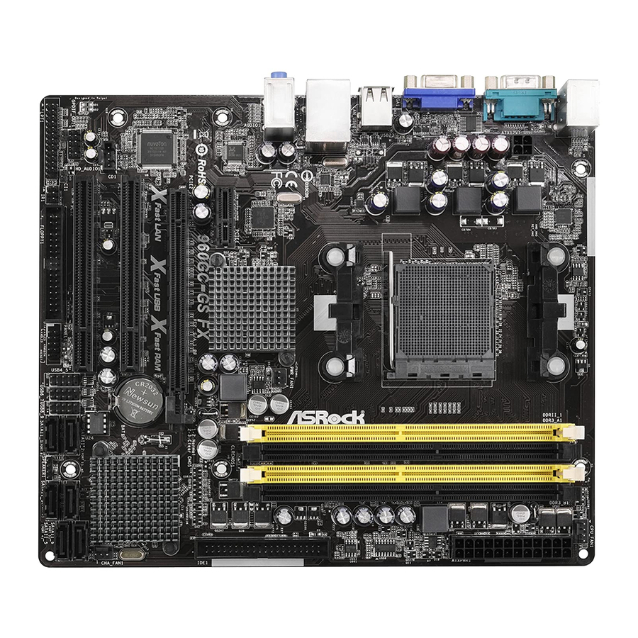
Page 12: Motherboard Layout
T: USB2 B: USB3 USB 2.0 Top: T: USB0 RJ-45 B: USB1 PWR_FAN1 760G CLRCMOS1 Chipset AUDIO CODEC PCIE1 960GC-GS FX RoHS PCIE2 Fast LAN Fast RAM Fast USB CMOS SB710 BATTERY PCI1 Chipset CHA_FAN1 16Mb BIOS SATAII_6 (PORT 5) -
Page 13: I/O Panel
1.5 I/O Panel PS/2 Mouse Port (Green) USB 2.0 Ports (USB01) LAN RJ-45 Port USB 2.0 Ports (USB23) Line In (Light Blue) D-Sub Port ** 4 Front Speaker (Lime) COM Port Microphone (Pink) PS/2 Keyboard Port (Purple) * There are two LED next to the LAN port. Please refer to the table below for the LAN port LED indications. -
Page 14: Installation
2. Installation This is a Micro ATX form factor motherboard. Before you install the motherboard, study the configuration of your chassis to ensure that the motherboard fits into it. Pre-installation Precautions Take note of the following precautions before you install motherboard components or change any motherboard settings. -
Page 15: Cpu Installation
2.1 CPU Installation Step 1. Unlock the socket by lifting the lever up to a 90 angle. Step 2. Position the CPU directly above the socket such that the CPU corner with the golden triangle matches the socket corner with a small triangle. Step 3. -
Page 16: Installation Of Memory Modules (Dimm)
2.3 Installation of Memory Modules (DIMM) This motherboard provides two 240-pin DDR2 (Double Data Rate 2) DIMM slots and two 240-pin DDR3 (Double Data Rate 3) DIMM slots, and supports Dual Channel Memory Technology. For dual channel configuration, you always need to install identical (the same brand, speed, size and chip-type) DDR2/ DDR3 DIMM pair in the slots of the same color. -
Page 17: Installing A Dimm
Installing a DIMM Please make sure to disconnect power supply before adding or removing DIMMs or the system components. Step 1. Unlock a DIMM slot by pressing the retaining clips outward. Step 2. Align a DIMM on the slot such that the notch on the DIMM matches the break on the slot. -
Page 18: Expansion Slots (Pci And Pci Express Slots)
2.4 Expansion Slots (PCI and PCI Express Slots) There are 2 PCI slots and 2 PCI Express slots on this motherboard. PCI Slots: PCI slots are used to install expansion cards that have the 32-bit PCI interface. PCIE Slots: PCIE1 (PCIE x1 slot) is used for PCI Express x1 lane width graphics cards. -
Page 19: Multi Monitor Feature
2.5 Multi Monitor Feature This motherboard supports multi monitor feature. With the internal VGA output support and the external add-on PCI Express VGA card, you can easily enjoy the benefits of multi monitor feature. Please refer to the following steps to set up a surround display environment: 1. - Page 20 D. Click “Extend my Windows desktop onto this monitor”. E. Right-click the display icon and select “Attached”, if necessary. F. Set the “Screen Resolution” and “Color Quality” as appropriate for the second monitor. Click “Apply” or “OK” to apply these new values. G.
-
Page 21: Jumpers Setup
2.6 Jumpers Setup The illustration shows how jumpers are setup. When the jumper cap is placed on pins, the jumper is “Short”. If no jumper cap is placed on pins, the jumper is “Open”. The illustration shows a 3-pin jumper whose pin1 and pin2 are “Short”... -
Page 22: Onboard Headers And Connectors
2.7 Onboard Headers and Connectors Onboard headers and connectors are NOT jumpers. Do NOT place jumper caps over these headers and connectors. Placing jumper caps over the headers and connectors will cause permanent damage of the motherboard! Floppy Connector (33-pin FLOPPY1) (see p.12 No. - Page 23 Serial ATA (SATA) Either end of the SATA data Data Cable cable can be connected to the SATA2 hard disk or the SATA2 (Optional) connector on this motherboard. USB 2.0 Headers Besides four default USB 2.0 USB_PWR ports on the I/O panel, there (9-pin USB4_5) DUMMY are three USB 2.0 headers on...
- Page 24 ® For Windows 8 / 8 64-bit / 7 / 7 64-bit / Vista / Vista 64-bit OS: Go to the "FrontMic" Tab in the Realtek Control panel. Adjust “Recording Volume”. SPDIF Out Connector Please connect the SPDIF_OUT connector of a (2-pin SPDIF_OUT1) HDMI VGA card to this header SPDIFOUT...
- Page 25 Chassis Speaker Header Please connect the chassis speaker to this header. (4-pin SPEAKER 1) (see p.12, No. 13) Infrared Module Header This header supports an optional wireless transmitting (5-pin IR1) and receiving infrared module. (see p.12, No. 21) Print Port Header This is an interface for print AFD# ERROR#...
- Page 26 CPU Fan Connector Please connect the CPU fan FAN_SPEED_CONTROL cable to the connector and (4-pin CPU_FAN1) CPU_FAN_SPEED +12V match the black wire to the (see p.12 No. 4) ground pin. 1 2 3 4 Though this motherboard provides 4-Pin CPU fan (Quiet Fan) support, the 3-Pin CPU fan still can work successfully even without the fan speed control function.
-
Page 27: Serial Ata2 (Sata2) Hard Disks Installation
Serial ATA2 (SATA2) Hard Disks Installation This motherboard adopts AMD SB710 chipset that supports Serial ATA2 (SATA2) hard disks and RAID (RAID 0, RAID 1, RAID 10 and JBOD) functions. You may in- stall SATA2 hard disks on this motherboard for internal storage devices. This section will guide you to install the SATA2 hard disks. -
Page 28: Driver Installation Guide
2.10 Driver Installation Guide To install the drivers to your system, please insert the support CD to your optical drive first. Then, the drivers compatible to your system can be auto-detected and listed on the support CD driver page. Please follow the order from up to bottom side to install those required drivers. -
Page 29: Installing Windows ® 8 / 8 64-Bit / 7 / 7 64-Bit / Vista
STEP 3: Use “RAID Installation Guide” to set RAID configuration. Before you start to configure RAID function, you need to check the RAID installation guide in the Support CD for proper configuration. Please refer to the BIOS RAID installation guide part of the document in the following path in the Support CD: .. -
Page 30: 64-Bit / Xp / Xp 64-Bit Without Raid Functions
® 2.12 Installing Windows 8 / 8 64-bit / 7 / 7 64-bit / Vista Vista 64-bit / XP / XP 64-bit Without RAID Functions ® If you want to install Windows 8 / 8 64-bit / 7 / 7 64-bit / Vista / Vista 64-bit / XP / XP 64-bit OS on your SATA / SATA2 HDDs without RAID functions, please follow... -
Page 31: Installing Windows ® 8 / 8 64-Bit / 7 / 7 64-Bit / Vista
® 2.12.2 Installing Windows 8 / 8 64-bit / 7 / 7 64-bit / Vista Vista 64-bit Without RAID Functions ® If you want to install Windows 8 / 8 64-bit / 7 / 7 64-bit / Vista / Vista 64-bit on your SATA / SATA2 HDDs without RAID functions, please follow below steps. -
Page 32: Bios Setup Utility
3. BIOS SETUP UTILITY 3.1 Introduction This section explains how to use the BIOS SETUP UTILITY to configure your sys- tem. The SPI Memory on the motherboard stores the BIOS SETUP UTILITY. You may run the BIOS SETUP UTILITY when you start up the computer. Please press <F2>... -
Page 33: Navigation Keys
System Time [ :00:09] or [SHIFT-TAB] to System Date [Tue 06/11/2013] select a field. BIOS Version : 960GC-GS FX P1.00 Use [+] or [-] to Processor Type : AMD Phenom(tm) 9550 Quad-Core configure system Time. Processor (64bit) Processor Speed : 2200MHz... -
Page 34: Oc Tweaker Screen
3.3 OC Tweaker Screen In the OC Tweaker screen, you can set up overclocking features. BIOS SETUP UTILITY Main OC Tweaker Advanced H/W Monitor Boot Security Exit CPU Configuration Overclocking may cause damage to your CPU and Overclock Mode [Auto] motherboard. -
Page 35: Processor Voltage
North Bridge Maximum Frequency It will display North Bridge Maximum Frequency for reference. Processor Maximum Voltage It will display Processor Maximum Voltage for reference. Multiplier/Voltage Change This item is set to [Auto] by default. If it is set to [Manual], you may adjust the value of Processor Frequency and Processor Voltage. -
Page 36: Dram Voltage
You can set one of the standard values as listed for DDR3 memory mod- ules: [400MHz DDR3_800], [533MHz DDR3_1066], [667MHz DDR3_1333] and [800MHz DDR3_1600]. DRAM Voltage Use this to select DRAM voltage. The default value is [Auto]. Memory Timing BIOS SETUP UTILITY OC Tweaker Memory Timing [Enabled]... - Page 37 Use this to adjust TRC values. The default value is [Auto]. Use this to adjust TWR values. The default value is [Auto]. TRFC Use this to adjust TRFC values. The default value is [Auto]. TRRD Use this to adjust TRRD values. The default value is [Auto]. TWTR Use this to adjust TWTR values.
-
Page 38: Advanced Screen
3.4 Advanced Screen In this section, you may set the configurations for the following items: CPU Configu- ration, Chipset Configuration, ACPI Configuration, Storage Configuration, PCIPnP Configuration, Floppy Configuration, Super IO Configuration and USB Configuration. BIOS SETUP UTILITY Main OC Tweaker H/W Monitor Boot Security... -
Page 39: Cpu Configuration
3.4.1 CPU Configuration BIOS SETUP UTILITY Advanced CPU Configuration Cool' n' Quiet [Enabled] [Enabled] Secure Virtual Machine Enhanced Halt State(C1E) [Disabled] CPU HTC [Enabled] CPU Thermal Throttle [Auto] Select Screen Select Screen Select Item Select Item Change Option Change Option General Help General Help Load Defaults... -
Page 40: Chipset Configuration
3.4.2 Chipset Configuration BIOS SETUP UTILITY Advanced Chipset Settings Onboard HD Audio [Auto] Front Panel [Auto] Onboard Lan [Enabled] Primary Graphics Adapter [PCI] Select Screen Select Item Change Option General Help Load Defaults Save and Exit Exit v02.54 (C) Copyright 1985-2003, American Megatrends, Inc. Onboard HD Audio Select [Auto], [Enabled] or [Disabled] for the onboard HD Audio feature. -
Page 41: Acpi Configuration
3.4.3 ACPI Configuration BIOS SETUP UTILITY Advanced ACPI Settings Select auto-detect or disable the STR feature. [Auto] Suspend To RAM Check Ready Bit [Auto] [Disabled] Away Mode Support Restore on AC / Power Loss [Power Off] Ring-In Power On [Disabled] PCI Devices Power On [Disabled] PS / 2 Keyboard Power On... - Page 42 ACPI HPET table Use this item to enable or disable ACPI HPET Table. The default value is [Enabled]. Please set this option to [Enabled] if you plan to use this moth- ® erboard to submit Windows certification.
-
Page 43: Storage Configuration
3.4.4 Storage Configuration BIOS SETUP UTILITY Advanced Configure onboard Storage Configuration serial ATA controller. Onboard SATA Controller [Enabled] [AHCI] SATA Operation Mode [Enabled] SATA IDE Combined Mode IDE1 Master [Hard Disk] IDE1 Slave [Not Detected] SATAII_1 [Not Detected] SATAII_2 [Not Detected] SATAII_3 Select Screen Select Screen... -
Page 44: Pcipnp Configuration
3.4.5 PCIPnP Configuration BIOS SETUP UTILITY Advanced Value in units of PCI Advanced PCI / PnP Settings clocks for PCI device latency timer PCI Latency Timer [32] register. PCI IDE BusMaster [Enabled] Select Screen Select Item Change Option General Help Load Defaults Save and Exit Exit... -
Page 45: Floppy Configuration
3.4.6 Floppy Configuration In this section, you may configure the type of your floppy drive. BIOS SETUP UTILITY Advanced Floppy Configuration Select the type of floppy drive connected to the Floppy A [Disabled] system. Select Screen Select Item Change Option General Help Load Defaults Save and Exit... -
Page 46: Super Io Configuration
3.4.7 Super IO Configuration BIOS SETUP UTILITY Advanced Configure Super IO Chipset Allow BIOS to Enable or Disable Floppy Controller. [Disabled] OnBoard Floppy Controller Serial Port Address [3F8/IRQ4] Infrared Port Address [Disabled] Select Screen Select Item Change Option General Help Load Defaults Save and Exit Exit... -
Page 47: Usb Configuration
3.4.8 USB Configuration BIOS SETUP UTILITY Advanced USB Configuration To enable or disable the onboard USB controllers. [Enabled] USB 2.0 Controller USB 2.0 Support [Enabled] Legacy USB Support [Enabled] USB Keyboard/Remote Power On [Disabled] USB Mouse Power On [Disabled] Select Screen Select Item Change Option General Help... -
Page 48: Hardware Health Event Monitoring Screen
3.5 Hardware Health Event Monitoring Screen In this section, it allows you to monitor the status of the hardware on your system, including the parameters of the CPU temperature, motherboard temperature, CPU fan speed, chassis fan speed, and the critical voltage. BIOS SETUP UTILITY Main OC Tweaker... -
Page 49: Boot Screen
3.6 Boot Screen In this section, it will display the available devices on your system for you to config- ure the boot settings and the boot priority. BIOS SETUP UTILITY Main OC Tweaker Advanced H/W Monitor Boot Security Exit Boot Settings Configure Settings during System Boot. -
Page 50: Security Screen
3.7 Security Screen In this section, you may set or change the supervisor/user password for the system. For the user password, you may also clear it. BIOS SETUP UTILITY Security Main OC Tweaker Advanced H/W Monitor Boot Exit Security Settings Install or Change the password. -
Page 51: Exit Screen
3.8 Exit Screen BIOS SETUP UTILITY Main OC Tweaker Advanced H/W Monitor Boot Security Exit Exit Options Exit system setup after saving the Save Changes and Exit changes. Discard Changes and Exit Discard Changes F10 key can be used for this operation. Load BIOS Defaults Load Performance Setup Default Load Power Saving Setup Default... -
Page 52: Software Support
Click on a specific item then follow the installation wizard to install it. 4.2.4 Contact Information If you need to contact ASRock or want to know more about ASRock, welcome to visit ASRock’s website at http://www.asrock.com; or you may contact your...
Need help?
Do you have a question about the 960GC-GS FX and is the answer not in the manual?
Questions and answers