ASROCK 990FX Extreme3 User Manual
User manual
Hide thumbs
Also See for 990FX Extreme3:
- Quick installation manual (182 pages) ,
- User manual (68 pages) ,
- User manual (182 pages)

Related Manuals for ASROCK 990FX Extreme3


Summary of Contents for ASROCK 990FX Extreme3
-
Page 1: User Manual
990FX Extreme3 User Manual Version 1.0 Published August 2011 Copyright©2011 ASRock INC. All rights reserved. -
Page 2: Copyright Notice
fi tness for a particular purpose. In no event shall ASRock, its directors, offi cers, employees, or agents be liable for any indirect, special, incidental, or consequential damages (including damages for loss of profi... -
Page 3: Table Of Contents
Contents 1. Introduction ..............5 Package Contents ..............5 Specifi cations ................6 Motherboard Layout ..............12 I/O Panel .................. 13 2. Installation ..............15 Pre-installation Precautions ..............15 CPU Installation ................. 16 Installation of CPU Fan and Heatsink ........16 Installation of Memory Modules (DIMM) ........ - Page 4 Main Screen ................43 OC Tweaker Screen..............44 Advanced Screen ..............48 3.4.1 CPU Confi guration ............49 3.4.2 North Bridge Confi guration ..........50 3.4.3 South Bridge Confi guration ..........51 3.4.4 Storage Confi guration ............52 3.4.5 Super IO Confi guration ............ 53 3.4.6 ACPI Confi...
-
Page 5: Introduction
In case any modifi cations of this manual occur, the updated ver- sion will be available on ASRock website without further notice. You may fi nd the latest VGA cards and CPU support lists on ASRock website as well. ASRock website http://www.asrock.com... -
Page 6: Specifi Cations
1.2 Specifications Platform - ATX Form Factor: 12.0-in x 8.6-in, 30.5 cm x 21.8 cm - All Solid Capacitor design (100% Japan-made high-quality Conductive Polymer Capacitors) - Support for Socket AM3+ processors - Support for Socket AM3 processors: AMD Phenom II X6 / X4 / X3 / X2 (except 920 / 940) / Athlon II X4 / X3 / X2 / Sempron processors... - Page 7 - CPU, VCCM, NB, SB Voltage Multi-adjustment Support CD - Drivers, Utilities, AntiVirus Software (Trial Version), CyberLink MediaEspresso 6.5 Trial, AMD Fusion, AMD Fusion Media Explorer, ASRock Software Suite (CyberLink DVD Suite - OEM and Trial; ASRock MAGIX Multimedia Suite - OEM)
- Page 8 7 / 7 64-bit / Vista / Vista 64-bit / XP / XP 64-bit compliant Certifi cations - FCC, CE, WHQL - ErP/EuP Ready (ErP/EuP ready power supply is required) (see CAUTION 16) * For detailed product information, please visit our website: http://www.asrock.com...
- Page 9 CAUTION! ASRock UCC (Unlock CPU Core) feature simplifi es AMD CPU activa- tion. Via a simple switch in the UEFI option “ASRock UCC”, you can unlock the extra CPU core to enjoy an instant performance boost. When UCC feature is enabled, the dual-core or triple-core CPU will boost to...
- Page 10 Please visit our website for the operation procedures of ASRock Extreme Tuning Utility (AXTU). ASRock website: http://www.asrock.com ASRock Instant Flash is a BIOS fl ash utility embedded in Flash ROM. This convenient BIOS update tool allows you to update system BIOS ®...
- Page 11 13. ASRock On/Off Play Technology allows users to enjoy the great audio ex- perience from the portable audio devices, such like MP3 player or mobile phone to your PC, even when the PC is turned off (or in ACPI S5 mode)! This motherboard also provides a free 3.5mm audio cable (optional) that...
-
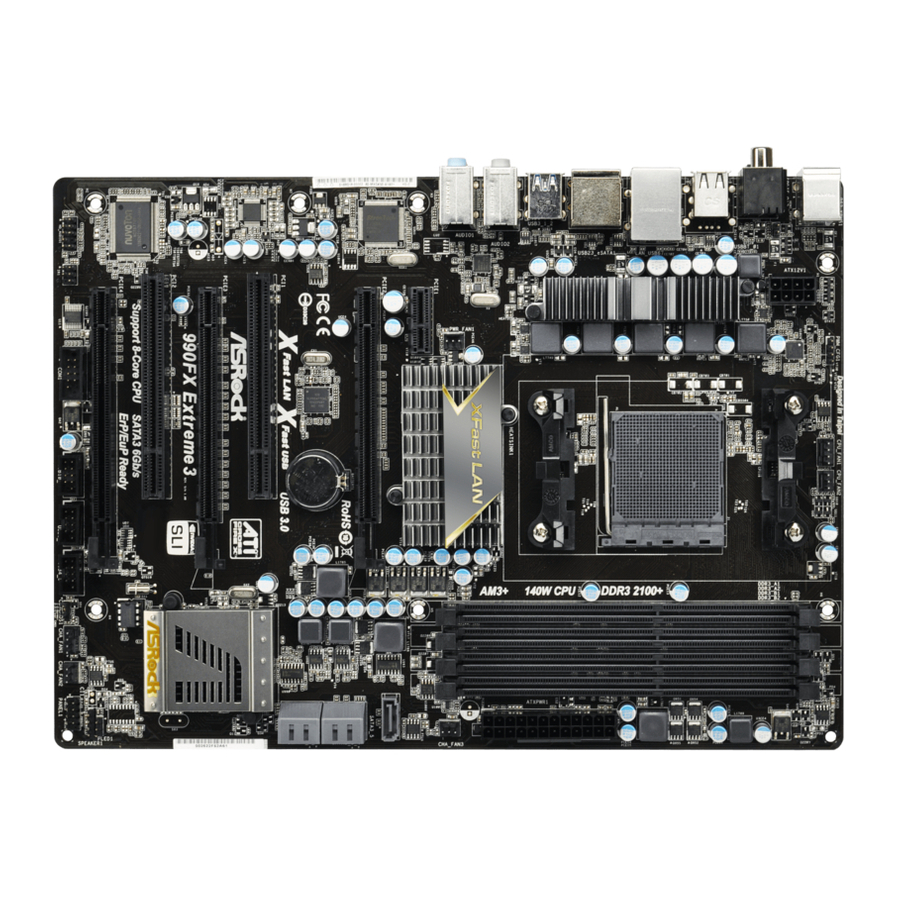
Page 12: Motherboard Layout
CHA_FAN3 PCIE1 SATA3_5 PCIE2 RoHS CMOS BATTERY Fast LAN Fast USB USB 3.0 PCI1 AUDIO CODEC SB950 PCIE3 Chipset 990FX Extreme3 PCI2 Support 8-Core CPU SATA3 6Gb/s 32Mb ErP/EuP Ready BIOS PLED1 PCIE4 SPEAKER1 COM1 USB10_11 USB8_9 USB4_5 CHA_FAN1 CHA_FAN2... -
Page 13: I/O Panel
1.4 I/O Panel PS/2 Mouse Port (Green) Front Speaker (Lime) Coaxial SPDIF Out Port Microphone (Pink) LAN RJ-45 Port USB 3.0 Ports (USB12) USB 2.0 Ports (USB23) ***12 eSATA3 Connector Side Speaker (Gray) USB 2.0 Ports (USB67) Rear Speaker (Black) USB 2.0 Ports (USB01) Central / Bass (Orange) Optical SPDIF Out Port... - Page 14 To enable Multi-Streaming function, you need to connect a front panel audio cable to the front panel audio header. After restarting your computer, you will fi nd “Mixer” tool on your system. Please select “Mixer ToolBox” , click “Enable playback multi-streaming”, and click “ok”. Choose “2CH”, “4CH”, “6CH”, or “8CH”...
-
Page 15: Installation
2. Installation This is an ATX form factor (12.0-in x 8.6-in, 30.5 cm x 21.8 cm) motherboard. Before you install the motherboard, study the confi guration of your chassis to ensure that the motherboard fi ts into it. Pre-installation Precautions Take note of the following precautions before you install motherboard components or change any motherboard settings. -
Page 16: Cpu Installation
2.1 CPU Installation Step 1. Unlock the socket by lifting the lever up to a 90 angle. Step 2. Position the CPU directly above the socket such that the CPU corner with the golden triangle matches the socket corner with a small triangle. Step 3. -
Page 17: Installation Of Memory Modules (Dimm)
2.3 Installation of Memory Modules (DIMM) This motherboard provides four 240-pin DDR3 (Double Data Rate 3) DIMM slots, and supports Dual Channel Memory Technology. For dual channel confi guration, you always need to install identical (the same brand, speed, size and chip-type) DDR3 DIMM pair in the slots. -
Page 18: Installing A Dimm
Installing a DIMM Please make sure to disconnect power supply before adding or removing DIMMs or the system components. Step 1. Unlock a DIMM slot by pressing the retaining clips outward. Step 2. Align a DIMM on the slot such that the notch on the DIMM matches the break on the slot. -
Page 19: Expansion Slots (Pci And Pci Express Slots)
2.4 Expansion Slots (PCI and PCI Express Slots) There are 2 PCI slots and 4 PCI Express slots on this motherboard. PCI Slots: PCI slots are used to install expansion cards that have the 32-bit PCI interface. PCIE Slots: PCIE1 (PCIE x1 slot; Black) is used for PCI Express cards with x1 lane width cards, such as Gigabit LAN card and SATA2 card. -
Page 20: Sli Tm And Quad Sli Tm Operation Guide
2.5 SLI and Quad SLI Operation Guide ® This motherboard supports NVIDIA and Quad SLI (Scalable Link Interface) technology that allows you to install up to three identical PCI Express x16 graphics ® ® cards. Currently, NVIDIA technology supports Windows XP / XP 64-bit / ®... -
Page 21: Driver Installation And Setup
Step3. Align and insert ASRock SLI_Bridge_2S Card to the goldfi ngers on each graphics card. Make sure ASRock SLI_Bridge_2S Card is fi rmly in place. ASRock SLI_Bridge_2S Card Step4. Connect a VGA cable or a DVI cable to the monitor connector or the DVI connector of the graphics card that is inserted to PCIE2 slot. - Page 22 ® For Windows Vista / Vista 64-bit / 7 / 7 64-bit OS: (For SLI and Quad SLI mode) A. Click the Start icon on your Windows taskbar. B. From the pop-up menu, select All Programs, and then click NVIDIA Corporation.
-
Page 23: Tm Tm Tm
2.6 CrossFireX , 3-Way CrossFireX and Quad CrossFireX Operation Guide This motherboard supports CrossFireX , 3-way CrossFireX and Quad CrossFireX features. CrossFireX technology offers the most advantageous means available of combining multiple high performance Graphics Processing Units (GPU) in a single PC. Combining a range of different operating modes with intelligent software design and an innovative interconnect mechanism, CrossFireX enables the highest possible level of performance and image quality in any 3D ®... - Page 24 Step 2. Connect two Radeon graphics cards by installing CrossFire Bridge on CrossFire Bridge Interconnects on the top of Radeon graphics cards. (CrossFire Bridge is provided with the graphics card you purchase, not bundled with this motherboard. Please refer to your graphics card vendor for details.) CrossFire Bridge Step 3.
- Page 25 2.6.1.2 Installing Three CrossFireX -Ready Graphics Cards Step 1. Install one Radeon graphics card to the PCIE2 slot. For the proper instal- lation procedures, please refer to section “Expansion Slots”. Step 2. Install one Radeon graphics card to the PCIE3 slot. For the proper instal- lation procedures, please refer to section “Expansion Slots”.
- Page 26 CrossFire Bridge Step 5. Connect the DVI monitor cable to the DVI connector on the Radeon graph- ics card in the PCIE2 slot. (You may use the DVI to D-Sub adapter to convert the DVI connector to D-Sub interface, and then connect the D-Sub monitor cable to the DVI to D-Sub adapter.)
- Page 27 2.6.2 Driver Installation and Setup Step 1. Power on your computer and boot into OS. Step 2. Remove the ATI driver if you have any VGA drivers installed in your sys- tem. The Catalyst Uninstaller is an optional download. We recommend using this utility to uninstall any previously installed Catalyst drivers prior to installation.
-
Page 28: Surround Display Information
Although you have selected the option “Enable CrossFire ”, the CrossFi- function may not work immediately. Your computer will automatically reboot. After restarting your computer, please confi rm whether the option “Enable CrossFire ” in “ATI Catalyst Control Center” is selected or not; if not, please select it again, and then you are able to enjoy the benefi... -
Page 29: Jumpers Setup
2.8 Jumpers Setup The illustration shows how jumpers are setup. When the jumper cap is placed on pins, the jumper is “Short”. If no jumper cap is placed on pins, the jumper is “Open”. The illustration shows a 3-pin jumper whose pin1 and pin2 are “Short”... -
Page 30: Onboard Headers And Connectors
2.9 Onboard Headers and Connectors Onboard headers and connectors are NOT jumpers. Do NOT place jumper caps over these headers and connectors. Placing jumper caps over the headers and connectors will cause permanent damage of the motherboard! SATA3_5 Serial ATA3 Connectors These fi... - Page 31 (9-pin USB10_11) (see p.12 No. 25) Infrared Module Header This header supports an optional wireless transmitting (5-pin IR1) and receiving infrared module. (see p.12 No. 27) Front Panel Audio Header This is an interface for the front panel audio cable that allows (9-pin HD_AUDIO1) convenient connection and (see p.12 No.
- Page 32 Connect the power switch, reset switch and system status indicator on the chassis to this header according to the pin assignments below. Note the positive and negative pins before connecting the cables. PWRBTN (Power Switch): Connect to the power switch on the chassis front panel. You may con- fi...
- Page 33 Chassis and Power Fan Connectors Please connect the fan cables to the fan connectors and (4-pin CHA_FAN1) match the black wire to the (see p.12 No. 21) +12V CHA_FAN_SPEED ground pin. CHA_FAN1/2/3 fan FAN_SPEED_CONTROL speed can be controlled through (3-pin CHA_FAN2) UEFI or AXTU.
- Page 34 ATX 12V Power Connector Please connect an ATX 12V power supply to this connector. (8-pin ATX12V1) (see p.12 No. 2) Though this motherboard provides 8-pin ATX 12V power connector, it can still work if you adopt a traditional 4-pin ATX 12V power supply. To use the 4-pin ATX power supply, please plug your power supply along with Pin 1 and Pin 5.
-
Page 35: Serial Ata3 (Sata3) Hard Disks Installation
2.10 Serial ATA3 (SATA3) Hard Disks Installation This motherboard adopts AMD SB950 chipset that supports Serial ATA3 (SATA3) hard disks and RAID (RAID 0, RAID 1, RAID 5 and RAID 10) functions. You may install SATA3 hard disks on this motherboard for internal storage devices. This sec- tion will guide you to install the SATA3 hard disks. -
Page 36: Sata3 Hdd Hot Plug Feature And Operation Operation Guide
3. Please make sure the SATA3 driver is installed into your system properly. The latest SATA3 driver is available on our support website: www.asrock.com 4. Make sure to use the SATA power cable & data cable, which are from our motherboard package. -
Page 37: How To Hot Plug A Sata3 Hdd
How to Hot Plug a SATA3 HDD: Points of attention, before you process the Hot Plug: Please follow the instructions below to process the Hot Plug, improper procedures will cause the SATA3 HDD damage and data loss. Please connect the SATA power cable’s Step 1 Step 2 Connect the SATA data cable to... -
Page 38: Driver Installation Guide
STEP 2: Make a SATA3 Driver Diskette. (Please use an USB fl oppy or a fl oppy disk.) A. Insert the ASRock Support CD into your optical drive to boot your system. B. During POST at the beginning of system boot-up, press the <F11> key, and then a window for boot devices selection appears. -
Page 39: Tm Tm
STEP 3: Use “RAID Installation Guide” to set RAID confi guration. Before you start to confi gure RAID function, you need to check the RAID installation guide in the Support CD for proper confi guration. Please refer to the BIOS RAID installation guide part of the document in the following path in the Support CD: .. -
Page 40: Installing Windows
® 2.15 Installing Windows 7 / 7 64-bit / Vista Vista 64-bit / XP / XP 64-bit Without RAID Functions ® If you want to install Windows 7 / 7 64-bit / Vista / Vista 64-bit / XP / XP 64- bit OS on your SATA3 HDDs without RAID functions, please follow the procedures below according to the OS you install. -
Page 41: Tm Tm
® 2.15.2 Installing Windows 7 / 7 64-bit / Vista Vista 64-bit Without RAID Functions ® If you want to install Windows 7 / 7 64-bit / Vista / Vista 64-bit on your SATA3 HDDs without RAID functions, please follow below steps. Using SATA3 HDDs with NCQ and Hot Plug functions (AHCI mode) STEP 1: Set up UEFI. -
Page 42: Uefi Setup Utility
3. UEFI SETUP UTILITY 3.1 Introduction This section explains how to use the UEFI SETUP UTILITY to confi gure your sys- tem. The SPI Memory on the motherboard stores the UEFI SETUP UTILITY. You may run the UEFI SETUP UTILITY when you start up the computer. Please press <F2>... -
Page 43: Navigation Keys
3.1.2 Navigation Keys Please check the following table for the function description of each navigation key. Navigation Key(s) Function Description Moves cursor left or right to select Screens Moves cursor up or down to select items + / - To change option for the selected items <Enter>... -
Page 44: Oc Tweaker Screen
ASRock UCC ASRock UCC (Unlock CPU Core) feature simplifi es AMD CPU activation. As long as a simple switch of the UEFI option “ASRock UCC”, you can unlock the extra CPU core to enjoy an instant performance boost. When UCC feature is enabled, the dual-core or triple-core CPU will boost to the... - Page 45 AMD Turbo Core Technology This allows you to adjust the AMD Turbo Core Technology feature. The default value is [Disabled]. Processor Maximum Frequency It will display Processor Maximum Frequency for reference. North Bridge Maximum Frequency It will display North Bridge Maximum Frequency for reference. Processor Maximum Voltage It will display Processor Maximum Voltage for reference.
- Page 46 Power Down Enable Use this item to enable or disable DDR power down mode. Bank Interleaving Interleaving allows memory accesses to be spread out over banks on the same node, or accross nodes, decreasing access contention. Channel Interleaving It allows you to enable Channel Memory Interleaving. Confi guration op- tions: [Disabled], [Auto].
- Page 47 Four Activate Window (tFAW) Use this item to change Four Activate Window (tFAW) Auto/Manual setting. The default is [Auto]. Voltage Control DRAM Voltage Use this to select DRAM Voltage. The default value is [Auto]. NB Voltage Use this to select NB Voltage. The default value is [Auto]. HT Voltage Use this to select HT Voltage.
-
Page 48: Advanced Screen
3.4 Advanced Screen In this section, you may set the confi gurations for the following items: CPU Confi gu- ration, Nouth Bridge Confi guration, South Bridge Confi guration, Storage Confi gura- tion, Super IO Confi guration, ACPI Confi guration, and USB Confi guration. Setting wrong values in this section may cause the system to malfunction. -
Page 49: Cpu Confi Guration
3.4.1 CPU Configuration Cool ‘n’ Quiet Use this item to enable or disable AMD’s Cool ‘n’ Quiet technology. The default value is [Enabled]. Confi guration options: [Enabled] and [Disabled]. ® If you install Windows 7 / Vista and want to enable this function, please set this item to [Enabled]. -
Page 50: North Bridge Confi Guration
3.4.2 North Bridge Configuration Primary Graphics Adapter This item will switch the PCI Bus scanning order while searching for video card. It allows you to select the type of Primary VGA in case of multiple video controllers. The default value of this feature is [PCI Express]. Con- fi... -
Page 51: South Bridge Confi Guration
3.4.3 South Bridge Configuration Onboard HD Audio Select [Auto], [Enabled] or [Disabled] for the onboard HD Audio feature. If you select [Auto], the onboard HD Audio will be disabled when PCI Sound Card is plugged. Front Panel Select [Auto] or [Disabled] for the onboard HD Audio Front Panel. On/Off Play Use this item to enable or disable On/Off Play Technology. -
Page 52: Storage Confi Guration
3.4.4 Storage Configuration SATA Controller Use this item to enable or disable the “SATA Controller” feature. SATA Mode Use this item to adjust SATA Mode. The default value of this option is [IDE Mode]. Confi guration options: [AHCI Mode], [RAID Mode] and [IDE Mode]. If you set this item to RAID mode, it is suggested to install SATA ODD driver on SATA3_5 or eSATA3 port. -
Page 53: Super Io Confi Guration
3.4.5 Super IO Configuration Serial Port Use this item to enable or disable the onboard serial port. Serial Port Address Use this item to set the address for the onboard serial port. Confi guration options: [3F8h / IRQ4] and [3E8h / IRQ4]. Infrared Port Use this item to enable or disable the onboard infrared port. -
Page 54: Acpi Confi Guration
3.4.6 ACPI Configuration Suspend to RAM Use this item to select whether to auto-detect or disable the Suspend-to- RAM feature. Select [Auto] will enable this feature if the OS supports it. Check Ready Bit Use this item to enable or disable the feature Check Ready Bit. Restore on AC/Power Loss This allows you to set the power state after an unexpected AC/power loss. - Page 55 ACPI HPET table Use this item to enable or disable ACPI HPET Table. The default value is [Enabled]. Please set this option to [Enabled] if you plan to use this moth- ® erboard to submit Windows Vista certifi cation.
-
Page 56: Usb Confi Guration
3.4.7 USB Configuration USB 2.0 Controller Use this item to enable or disable the use of USB 2.0 controller. USB 3.0 Controller Use this item to enable or disable the use of USB 3.0 controller. Legacy USB Support Use this option to select legacy support for USB devices. There are four confi... -
Page 57: Hardware Health Event Monitoring Screen
3.5 Hardware Health Event Monitoring Screen In this section, it allows you to monitor the status of the hardware on your system, including the parameters of the CPU temperature, motherboard temperature, CPU fan speed, chassis fan speed, and the critical voltage. CPU Fan 1 &... -
Page 58: Boot Screen
3.6 Boot Screen In this section, it will display the available devices on your system for you to confi g- ure the boot settings and the boot priority. Setup Prompt Timeout This shows the number of seconds to wait for setup activation key. 65535(0xFFFF) means indefi... -
Page 59: Security Screen
3.7 Security Screen In this section, you may set or change the supervisor/user password for the system. For the user password, you may also clear it. -
Page 60: Exit Screen
3.8 Exit Screen Save Changes and Exit When you select this option, it will pop-out the following message, “Save confi guration changes and exit setup?” Select [Yes] to save the changes and exit the UEFI SETUP UTILITY. Discard Changes and Exit When you select this option, it will pop-out the following message, “Discard changes and exit setup?”... -
Page 61: Software Support
Click on a specifi c item then follow the installation wizard to install it. 4.2.4 Contact Information If you need to contact ASRock or want to know more about ASRock, welcome to visit ASRock’s website at http://www.asrock.com; or you may contact your... - Page 62 Installing OS on a HDD Larger Than 2TB in AHCI Mode ® This motherboard adopts UEFI BIOS that allows Windows OS to be installed on a large size HDD (>2TB). Please follow the procedures below to install the operating system. ®...
-
Page 63: Installing Os On A Hdd Larger Than 2Tb In Raid Mode
Installing OS on a HDD Larger Than 2TB in RAID Mode ® This motherboard adopts UEFI BIOS that allows Windows OS to be installed on a large size HDD (>2TB). Please follow the procedures below to install the operating system. ®... - Page 64 7. And then key in drvcfg –s [Drv number] [Ctrl number] to enter Raid Utility. For example: key in drvcfg –s 4E B5. 8. Choose Logical Drive Main Menu to set up Raid Drive. 9. Choose Logical Drive Create Menu to create a Raid Drive. 10.
- Page 65 11. Press Space on keyboard to toggle checkbox. 12. Choose Ld Size setting, and key in the Raid size. 13. After set up Raid size, please click Start to Create. 14. Press <F10> to exit Utility. 15. During reboot, please press <F11> to enter Boot Manual. Choose UEFI: SCSI CD/DVD Drive.
- Page 66 ® 16. Follow Windows Installation Guide to install OS. ® If you install Windows 7 64-bit / Vista 64-bit in a large hard disk (ex. Disk ® volume > 2TB), it may take more time to boot into Windows or install driver/ utilities.
- Page 67 B. Disable “Volume Shadow Copy” service. a. Type “computer management” in the Start Menu, then press “Enter”. b. Go to “Services and Applications>Services”; Then double click “Volume Shadow Copy”. c. Set “Startup type” to “Disable” then Click “OK”.
- Page 68 C. Reboot your system. D. After reboot, please start to install motherboard drivers and utilities. ® Windows 7 64-bit: A. Please request the hotfi x KB2505454 through this link: http://support.microsoft.com/kb/2505454/ ® B. After installing Windows 7 64-bit, install the hotfi x kb2505454. (This may take a long time;...
Need help?
Do you have a question about the 990FX Extreme3 and is the answer not in the manual?
Questions and answers