Siemens MICROMASTER Operating Instructions Manual
Hide thumbs
Also See for MICROMASTER:
- Reference manual (78 pages) ,
- Operating instructions manual (22 pages)
Table of Contents
Advertisement
MICROMASTER
Operating Instructions
Contents
Safety Instructions ..............................................................2
1. OVERVIEW ......................................................................3
2. INSTALLATION ...............................................................4
4. OPERATING MODES ....................................................17
5. SYSTEM PARAMETERS ...............................................20
6. FAULT CODES ..............................................................34
7. SPECIFICATIONS..........................................................35
8. SUPPLEMENTARY INFORMATION .............................37
© Siemens plc 1997
G85139-H1750-U049-B
26/09/97
Advertisement
Table of Contents

Related Manuals for Siemens MICROMASTER


Summary of Contents for Siemens MICROMASTER
-
Page 1: Table Of Contents
Safety Instructions ..............2 1. OVERVIEW ..............3 2. INSTALLATION ...............4 3. FRONT PANEL CONTROLS & BASIC OPERATION ...14 4. OPERATING MODES ............17 5. SYSTEM PARAMETERS ..........20 6. FAULT CODES ..............34 7. SPECIFICATIONS............35 8. SUPPLEMENTARY INFORMATION ......37 © Siemens plc 1997 G85139-H1750-U049-B 26/09/97... -
Page 2: Safety Instructions
European Machinery Directive the system up and repair faults. These personnel must be thoroughly acquainted with The MICROMASTER inverter series does not fall under the scope of all the warnings and operating procedures the Machinery Directive. However, the products have been fully contained in this manual. -
Page 3: Overview
The MICROMASTERS are a range of frequency inverters for controlling the speed of three phase AC motors. Various models are available, ranging from the compact 120 W single phase input MICROMASTER up to the 7.5 kW three phase input MICROMASTER. -
Page 4: Installation
For optimum performance, there should be a good conductive bond between filter and metal mounting plate. On no account must safety regulations be compromised when installing inverters! G85139-H1750-U049-B © Siemens plc 1997 26/09/97... - Page 5 The control cable must be kept separate from the motor and mains cables. CONTROL CABLE MOTOR * Note: Screen must be terminated CABLE * at the motor. Figure 1: Example of an RFI Suppression Filter Installation © Siemens plc 1997 G85139-H1750-U049-B 26/09/97...
-
Page 6: Mechanical Installation
2. Install cabinet cooling fan(s) if necessary, Note: Typical dissipation (Watts) = 3% of inverter rating. T = Allowable temperature rise within cabinet in °C. 3.1 = Specific heat of air at sea level. G85139-H1750-U049-B © Siemens plc 1997 26/09/97... - Page 7 A = 147 x 73 x 141 160 175 MM110 B = 184 x 149 x 172 174 184 MM150 MM220 C = 215 x 185 x 195 204 232 MM300 MM400 MM550 MM750 Figure 2: Mechanical Installation Diagram © Siemens plc 1997 G85139-H1750-U049-B 26/09/97...
-
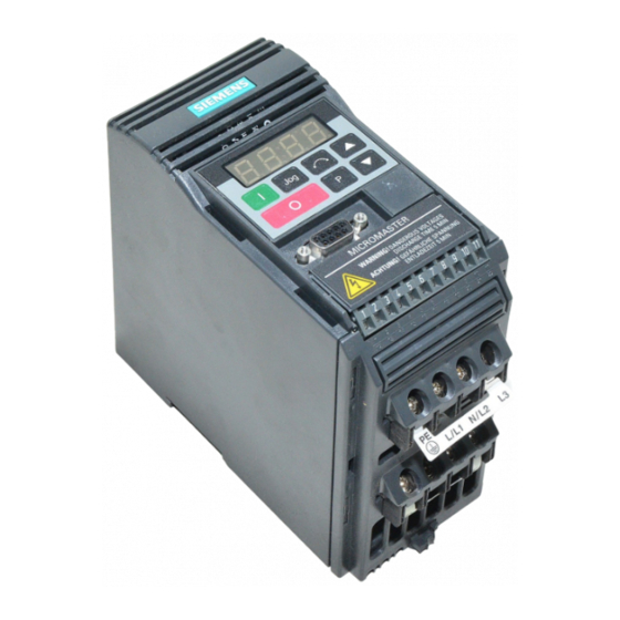
Page 8: Electrical Installation
2. INSTALLATION 2.3 Electrical Installation The electrical connectors on the MICROMASTER are shown in Figure 3. Connect the cables to the power and control terminal blocks in accordance with the information supplied in sections 2.3.1 - 2.3.4. Ensure that the leads are connected correctly and the equipment is properly earthed as shown in Figure 3. - Page 9 English Control Terminals PE L/L1 N/L2 Mains Input Terminals Motor Terminals FILTER MOTOR (Class B only) CONTACTOR MICROMASTER FUSES SINGLE PHASE TYPICAL INSTALLATION MOTOR FILTER CONTACTOR MICROMASTER FUSES THREE PHASE Figure 3: Power Connections © Siemens plc 1997 G85139-H1750-U049-B 26/09/97...
- Page 10 F: Mains cable input (22.8 mm diameter; accepts cables up to 14.5 mm diameter) G: Motor cable input (22.8 mm diameter; accepts cables up to 14.5 mm diameter) Figure 4: Power Connections Access Diagram - Frame Size B G85139-H1750-U049-B © Siemens plc 1997 26/09/97...
- Page 11 Mains cable input (22.8 mm diameter; accepts cables up to 14.5 mm diameter) Motor cable input (22.8 mm diameter; accepts cables up to 14.5 mm diameter) Figure 5: Power Connections Access Diagram - Frame Size C © Siemens plc 1997 G85139-H1750-U049-B 26/09/97...
-
Page 12: Control Connections
(7.5 - 33 V, max. 5 mA) Analogue Input Power Supply (0/2 - 10 V) (input impedance = 70 k ) PI Feedback Transducer or other load (+15 V, max. 50 mA) Control Terminal Block Figure 6: Control Connections G85139-H1750-U049-B © Siemens plc 1997 26/09/97... -
Page 13: Block Diagram
V: 0 - 10 V 2 - 10 V AIN+ AIN- – 24 V RS485 DIN1 DIN2 DIN3 Power Supply for +15V PI Feedback Transducer or other load. RL1B RL1C U, V, W Figure 8: Block Diagram © Siemens plc 1997 G85139-H1750-U049-B 26/09/97... -
Page 14: Front Panel Controls & Basic Operation
Press to DECREASE frequency. Used to change parameter numbers or values to lower settings during the parameterisation procedure. Disabled if P124 = 0. Press to access parameters. Disabled if P051 - P053 = 14 when using digital inputs. Figure 9: Front Panel G85139-H1750-U049-B © Siemens plc 1997 26/09/97... -
Page 15: Basic Operation
1.5 seconds while the inverter is stopped. (3) The inverter is programmed at the factory for standard applications on Siemens four-pole standard motors. When using other motors it is necessary to enter the specifications from the motor’s rating plate into parameters P081 to P085 (see Figure 10) . - Page 16 It assumes that a standard Siemens four-pole motor is connected to the inverter (see section 3.2.1 if a different motor type is being used) .
-
Page 17: Operating Modes
Stator Resistance - too high a value may cause overcurrent trips (8) Set the external on/off switch to ON. Turn the potentiometer (or adjust the analogue control voltage) until the desired frequency is displayed on the inverter. © Siemens plc 1997 G85139-H1750-U049-B 26/09/97... - Page 18 Several inverters can be connected to an external control unit at the same time. The inverters can be addressed individually. For further information, refer to the following documents (available from your local Siemens office) : E20125-B0001-S302-A1 Application of the USS Protocol in SIMOVERT Units 6SE21 and...
- Page 19 4.6 Closed Loop Control 4.6.1 General Description The MICROMASTER provides a PI control function for closed loop control (see Figure 11) . PI control is ideal for temperature or pressure control, or other applications where the controlled variable changes slowly or where transient errors are not critical.
-
Page 20: System Parameters
.00 and .99 are valid) and then press P twice to return to the parameter display. If parameters are changed accidentally, all parameters can be reset to their default values by setting parameter P944 to 1 and then pressing P. G85139-H1750-U049-B © Siemens plc 1997 26/09/97... - Page 21 F re q u e n c y m a x 0 H z R a m p d o w n T im e tim e (0 - 6 5 0 s ) © Siemens plc 1997 G85139-H1750-U049-B 26/09/97...
-
Page 22: System Parameters
1 = Parameters from P001 to P009 can be set and all other parameters can only be read. 2 = All parameters can be read/set but P009 automatically resets to 0 when power is removed. 3 = All parameters can be read/set. G85139-H1750-U049-B © Siemens plc 1997 26/09/97... - Page 23 Frequency corresponding to the lowest analogue input value, i.e. P021 [0.00] 0 V or 2 V. This can be set to a higher value than P022 to give an inverse relationship between analogue input and frequency output (see diagram in P022). © Siemens plc 1997 G85139-H1750-U049-B 26/09/97...
- Page 24 If jog left is enabled (DINn = 8), this parameter controls the frequency at which the inverter will run when the switch is closed. Unlike other [5.00] setpoints, it can be set lower than the minimum frequency. G85139-H1750-U049-B © Siemens plc 1997 26/09/97...
- Page 25 FF 6 FF 7 P050 = 0 P050 = 1 P050 = 2 P050 = 3 P050 = 4 P050 = 5 P050 = 6 or 7 Fixed setpoints not inverted. Fixed setpoints inverted. © Siemens plc 1997 G85139-H1750-U049-B 26/09/97...
- Page 26 RUN to FF4 (P044) RUN to FF5 (P046) RUN to FF6 (P047) RUN to FF7 (P048) 0 = 12.5 ms P056 Digital input debounce time 0 - 2 1 = 7.5 ms 2 = 2.5 ms G85139-H1750-U049-B © Siemens plc 1997 26/09/97...
- Page 27 This parameter is used when P061 = 9. The relay switches on when [1.0] the motor current is greater than the value of P065 and switches off when the current falls to 90% of the value of P065 (hysteresis). © Siemens plc 1997 G85139-H1750-U049-B 26/09/97...
- Page 28 5Hz, when operating at switching frequencies greater than 4kHz and with boost values greater than 100% (P078 + P079). These are typically as follows: Model P076 = 0 or 1 2 or 3 MM37/3- MM750/3 50%xP083 80%xP083 G85139-H1750-U049-B © Siemens plc 1997 26/09/97...
- Page 29 0 - 30 Up to 31 inverters can be connected via the serial link and controlled P091 by a computer or PLC using the USS protocol. This parameter sets a unique address for the inverter. © Siemens plc 1997 G85139-H1750-U049-B 26/09/97...
- Page 30 If P101 = 1 then the rating is displayed in hp. Inverter type (model) 1 - 7 Read-only parameter. P112 žžž 1 = MICROMASTER series 2 (MM2) 2 = COMBIMASTER 3 = MIDIMASTER 4 = MICROMASTER Junior (MMJ) 5 = MICROMASTER series 3 (MM3) 6 = MICROMASTER Vector (MMV) 7 = MIDIMASTER Vector (MDV) Read-only parameter.
- Page 31 Transducer type 0 - 1 0 = An increase in motor speed causes an increase in sensor P208 voltage/current output. 1 = An increase in motor speed causes a decrease in sensor voltage/current output. © Siemens plc 1997 G85139-H1750-U049-B 26/09/97...
- Page 32 003 = Voltage limit active 005 = Inverter over-temperature (Internal PTC) Reset to factory default settings 0 - 1 Set to ‘1’ and then press P to reset all parameters except P101 to the P944 factory default settings. G85139-H1750-U049-B © Siemens plc 1997 26/09/97...
- Page 33 EEPROM - this is approximately 50,000 write cycles. Exceeding this number of write cycles would result in corruption of the stored data and subsequent data loss. The number of read cycles are unlimited. © Siemens plc 1997 G85139-H1750-U049-B 26/09/97...
-
Page 34: Fault Codes
When the fault has been corrected the inverter can be reset. To do this press button P twice (once to display P000 and the second time to reset the fault), or erase the fault via a binary input (see parameters P051 - P053 in section 5) or via the serial interface. G85139-H1750-U049-B © Siemens plc 1997 26/09/97... -
Page 35: Specifications
All 1 AC and 3 AC 230 V MICROMASTERS (excluding MM400/2) are suitable for 208 V operation. All 3 AC 230 V MICROMASTERS can operate on 1 AC 230 V (MM300/2 requires an external line choke, e.g. 4EM6100-3CB). 380 V - 500 V Three Phase MICROMASTER Inverters Order No. (6SE92 ..) - Page 36 Additional RFI suppression filter Clear Text Display (OPM2) PROFIBUS module (CB15) Please contact your local SIMOVIS software for control via PC Siemens sales office for further details Output chokes and line chokes Output filters IP20 (NEMA 1) Accessory Kit G85139-H1750-U049-B ©...
-
Page 37: Supplementary Information
The display flashes whenever a byte is received, thus giving a basic indication that a serial link connection is established. If ‘100’ flashes on the display continuously, this usually indicates a bus termination fault. © Siemens plc 1997 G85139-H1750-U049-B 26/09/97... -
Page 38: Supplementary Information
This approach is only applicable to radio communication transmitting apparatus. The MICROMASTER units do not have an intrinsic function until connected with other components (e.g. a motor). Therefore, the basic units are not allowed to be CE marked for compliance with the EMC directive. - Page 39 Burst Interference EN 61000-4-4 1 kV power cables, 0.5 kV control Note: The MICROMASTERS are intended exclusively for professional applications. Therefore, they do not fall within the scope of the harmonics emissions specification EN 61000-3-2. © Siemens plc 1997 G85139-H1750-U049-B 26/09/97...
- Page 40 The inverter’s packaging is re-usable. Retain the packaging or return it to the manufacturer for future use. If the unit has been in storage (non-operational) for more than one year, you must re-form the DC-link capacitors before use. Refer to your local Siemens sales office for advice on the procedure. Dismantling and Disposal The unit can be broken-down to its component parts by means of easily-released screw and snap connectors.
- Page 41 P132 P044 20.00 P134 P045 P135 P046 25.00 P137 P047 30.00 P140 P048 35.00 P141 P050 P142 P051 P143 P052 P201 P053 P202 P056 P203 0.00 P061 P205 P062 P206 P063 P207 P064 P208 © Siemens plc 1997 G85139-H1750-U049-B 26/09/97...
- Page 42 Herausgegeben vom Siemens plc Sir William Siemens House Bereich Antriebs-, Schalt- und Installationstechnik Princess Road Geschäftsgebiet Antriebstechnik Manchester M20 8UR Postfach 3269, D-91050 Erlangen Änderungen vorbehalten G85139-H1750-U049-B Bestell-Nr. 6SE9286-4AA86 Specification subject to change without prior notice © Siemens plc 1997...
Need help?
Do you have a question about the MICROMASTER and is the answer not in the manual?
Questions and answers