
Related Manuals for UNI-T UT33B


Summary of Contents for UNI-T UT33B
-
Page 1: Table Of Contents
Model UT33B/C/D: OPERATING MANUAL Table of Contents (1) Title Page Overview Unpacking Inspection Safety Information Rules For Safe Operation International Electrical Symbols The Meter structure Functional Buttons Measurement Operation DC Voltage Measurement AC Voltage Measurement DC Current Measurement D. Measuring Resistance... - Page 2 Model UT33B/C/D: OPERATING MANUAL Table of Contents (2) Title Page Square Wave Output General Specifications Accuracy Specifications DC Voltage AC Current C. DC Current D. Resistance Diodes and Continuity Measurement Temperature G. Battery Test Square Wave Output Maintenance General Service...
-
Page 3: Overview
To avoid electric shock or personal injury, read the “Safety Information” and “Rules for Safety Operation” carefully before using the Meter. The Model UT33B, UT33C and UT33D Multimeters (hereafter referred as “the Meter”) are 3 1/2 digits with steady operations, fashionable design and highly reliable hand-held measuring instrument. -
Page 4: Unpacking Inspection
Model UT33B/C/D: OPERATING MANUAL Unpacking Inspection Open the package case and take out the Meter. Check the following items carefully to see any missing or damaged part: Item Description English Operating Manual 1 piece 1 pair Test Lead 1 piece... -
Page 5: Safety Information
Model UT33B/C/D: OPERATING MANUAL Safety Information(1) Safety Information This Meter complies with the standards IEC61010: in pollution degree 2, overvoltage category (CAT I 600V, CAT II 300V) and double insulation. CAT. I: Signal level, special equipment or parts of equipment, telecommunication, electronic, etc., with smaller transient overvoltages than overvoltages CAT. - Page 6 Model UT33B/C/D: OPERATING MANUAL Safety Information(2) In this manual, a Warning identifies conditions and actions that pose hazards to the user, or may damage the Meter or the equipment under test.A Note identifies the information that user should pay attention on.
-
Page 7: Rules For Safe Operation
Model UT33B/C/D: OPERATING MANUAL Rules For Safe Operation (1) Warning To avoid possible electric shock or personal injury, and to avoid possible damage to the Meter or to the equipment under test, adhere to the following rules: l Before using the Meter inspect the case. Do not use the Meter if it is damaged or the case (or part of the case) is removed. - Page 8 Model UT33B/C/D: OPERATING MANUAL Rules For Safe Operation (2) prevent damage of the Meter. l When the Meter working at an effective voltage over 60V in DC or 42V rms in AC, special care should be taken for there is danger of electric shock.
- Page 9 Model UT33B/C/D: OPERATING MANUAL Rules For Safe Operation (3) l Remove test leads and temperature probe from the Meter and turn the Meter power off before opening the Meter case. l When servicing the Meter, use only the same model number or identical electrical specifications replacement parts.
-
Page 10: International Electrical Symbols
Model UT33B/C/D: OPERATING MANUAL International Electrical Symbols AC or DC AC Current DC Current Earth Ground Double Insulated. Low Battery. Diode. Fuse. Continuity Test Safety Rules Conforms to Standards of European Union. -
Page 11: The Meter Structure
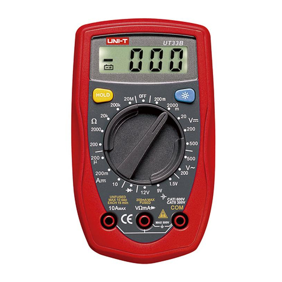
Model UT33B/C/D: OPERATING MANUAL The Meter Structure The Meter Structure (figure 1) LCD Display HOLD Button Display Backlight Button Rotary Switch COM Input Terminal 10A Input Terminal Other Input Terminals (figure 1) -
Page 12: Functional Buttons
Model UT33B/C/D: OPERATING MANUAL Functional Buttons Below table indicated for information about the functional button operations. Button Operation Performed l Press HOLD once to enter hold mode. HOLD button l Press HOLD again to exit hold mode. l In Hold mode, is displayed and the present value is shown. -
Page 13: Measurement Operation
Model UT33B/C/D: OPERATING MANUAL Measurement Operation(1) A. DC Voltage Measurement (see figure 2) Warning To avoid harms to you or damages to the Meter from electric shock, please do not attempt to measure voltages higher than 500V although readings may be obtained. - Page 14 Model UT33B/C/D: OPERATING MANUAL Measurement Operation (2) Note If the value of voltage to be measured is unknown, use the maximum measurement position (500V) and reduce the range step by step until a satisfactory reading is obtained. The LCD displays “1” indicating the existing selected range is overload; it is required to select a higher range in order to obtain a correct reading.
-
Page 15: Ac Voltage Measurement
Model UT33B/C/D: OPERATING MANUAL Measurement Operation (3) AC Voltage Measurement (see figure 2) Warning To avoid harms to you or damages to the Meter from electric shock, please do not attempt to measure voltages higher than 500Vrms although readings may be obtained. - Page 16 Model UT33B/C/D: OPERATING MANUAL Measurement Operation (4) Note If the value of voltage to be measured is unknown, use the maximum measurement position (500V) and reduce the range step by step until a satisfactory reading is obtained. The LCD displays “1” indicating the existing selected range is overload, it is required to select a higher range in order to obtain a correct reading.
-
Page 17: Dc Current Measurement
Model UT33B/C/D: OPERATING MANUAL Measurement Operation (5) C. DC Current Measurement (see figure 3) Warning Never attempt an in-circuit current measurement where the voltage between terminals and ground is greater than 60V. If the fuse burns out during measurement, the Meter may be damaged or the operator himself may be hurt. - Page 18 Model UT33B/C/D: OPERATING MANUAL Measurement Operation (6) The Model UT33B: the current measurement has 3 measurement positions on the rotary switch: 200 A, 200mA and 10A. The Model UT33C/UT33D: the current measurement has 4 measurement positions on the rotary switch: 2000 A, 20mA, 200mA and 10A To measure current, do the following: 1.
- Page 19 Model UT33B/C/D: OPERATING MANUAL Measurement Operation (7) Note l If the value of current to be measured is unknown, use the maximum measurement position (10A) l and reduce the range step by step until a satisfactory reading is obtained. l When current measurement has been completed, disconnect the connection between the testing leads l and the circuit under test.
-
Page 20: Measuring Resistance
To avoid damages to the Meter or to the devices under test, disconnect circuit power and discharge all the high-voltage capacitors before measuring resistance. The Model UT33B/UT33C: The resistance measurement positions are: 200 , 2000 ¸, 20k , 200k and 20M The Model UT33D: The resistance measurement... -
Page 21: Measurement Operation
Model UT33B/C/D: OPERATING MANUAL Measurement Operation (9) Insert the red test lead into the V mA terminal and the black test lead into the COM terminal. Set the rotary switch to an appropriate measurement position in range. Connect the test leads across with the object being measured. -
Page 22: Diodes And Continuity Measurement
Model UT33B/C/D: OPERATING MANUAL Measurement Operation (10) between the testing leads and the circuit under test. Diodes and Continuity Measurement (see figure 5) Testing Diodes Warning To avoid amages to the Meter or to the devices under test, disconnect circuit power and discharge all the high-voltage capacitors before diodes. - Page 23 Model UT33B/C/D: OPERATING MANUAL Measurement Operation (11) across the junction. A good silicon junction drops between 0.5V and 0.8V. To test a diode out of a circuit, connect the Meter as follows: Insert the red test lead into the V mA terminal and the black test lead into the COM terminal.
-
Page 24: To Test For Continuity
Model UT33B/C/D: OPERATING MANUAL Measurement Operation (12) Connect the test leads to the proper terminals as said above to avoid error display. The LCD will display “1” indicating open-circuit for wrong connection. The unit of diode is Volt (V), displaying the positive-connection voltage-drop value. -
Page 25: Temperature Measurement
Model UT33B/C/D: OPERATING MANUAL Measurement Operation (13) When continuity testing has been completed, disconnect the connection between the testing leads and the circuit under test. Model UT33C: Temperature Measurement (see figure 6) Warning To avoid harms to you or damages to the Meter, please do not attempt to input voltages higher than 60V in DC or 30V in AC. - Page 26 Model UT33B/C/D: OPERATING MANUAL Measurement Operation (14) Set the rotary switch to C or Place the temperature probe to the object being measured. The measured value shows on the display. Note The Meter automatically displays the temperature value inside the Meter when there is no temperature probe connection.
-
Page 27: Battery Test
Model UT33B/C/D: OPERATING MANUAL Measurement Operation (15) The Model UT33B: Battery Test (see figure 7) Warning To avoid harms to you or damages to the Meter, please do not attempt to input voltages higher than 60V in DC or 30V in AC. -
Page 28: Square Wave Output
Model UT33B/C/D: OPERATING MANUAL Measurement Operation (16) Note When battery testing has been completed, disconnect the connection between the testing leads and the circuit under test. H. The Model UT33D: Square Wave Output Warning To avoid damages to the Meter, do not allow output terminals (red test lead) to reach higher than 10V. -
Page 29: General Specifications
Model UT33B/C/D: OPERATING MANUAL General Specifications(1) When square wave output testing has been completed, disconnect the connection between the testing leads and the circuit under test. General Specifications (including transient overvoltage) Maximum Voltage between any Terminals and Grounding: 500V rms. - Page 30 Model UT33B/C/D: OPERATING MANUAL General Specifications(2) Altitude:Operating: 2000 m. Storage: 10000 m. Battery Type: One piece of 9V Battery NEDA 1604 or 6F22 or 006P. Battery Deficiency: Display: Negative reading: Display: Overloading: Display: 1. Dimensions (HxWxL): 130 x 73.5 x 35mm.
-
Page 31: Accuracy Specifications
Model UT33B/C/D: OPERATING MANUAL Accuracy Specifications(1) Accuracy: (a% reading + b digits), guarantee for 1 year. Operating temperature: 23 Relative humidity: <75%. Temperature coefficient: 0.1 x (specified accuracy) / 1 A. DC Voltage Accuracy Overload Range Resolution Protection UT33B UT33C... -
Page 32: Ac Current
Model UT33B/C/D: OPERATING MANUAL Accuracy Specifications(2) AC Voltage Accuracy Overload Range Resolution Protection UT33B UT33C UT33D 200V 100mV (1.2%+10) 500V DC or AC 500V Remarks: Input impedance: approx. 5M Displays effective value of sine wave (mean value response). Frequency response 40Hz ~ 400Hz. -
Page 33: Dc Current
Model UT33B/C/D: OPERATING MANUAL Accuracy Specifications(3) DC Current Accuracy Overload Range Resolution Protection UT33B UT33C UT33D (1%+2) 200 A 0.1 A 315mA, 250V fast type fuse: 2000 A (1%+2) 5x20mm 20mA 10 A 200mA 100 A (1.2%+2) 10mA (2%+5) Un-Fused... -
Page 34: Resistance
Model UT33B/C/D: OPERATING MANUAL Accuracy Specifications(4) D. Resistance Accuracy Overload Range Resolution Protection UT33B UT33C UT33D (0.8%+5) 2000 250V DC (0.8%+2) or AC 200k (1%+5) 200M 100k [5%(reading-10)+10]... -
Page 35: Diodes And Continuity Measurement
Model UT33B/C/D: OPERATING MANUAL Accuracy Specifications(5) E. Diodes and Continuity Measurement (Continuity test only for UT33C/UT33D) Range Resolution Remark Overload Protection Displays approximate forward voltage drop: 0.5V~0.8V. 250V DC or AC Buzzer beeps at <70 F. The Model UT33C: Temperature... -
Page 36: Battery Test
Model UT33B/C/D: OPERATING MANUAL Accuracy Specifications(6) G. The Model UT33B: Battery Test Range Resolution Internal Resistance 10mV 10mV 1.8k 1.5V 10mV H. The Model UT33D: Square Wave Output Illustration Range Approx. output 50Hz square wave signal. As a simple signal source with 47k resistance output. -
Page 37: Maintenance
Model UT33B/C/D: OPERATING MANUAL Maintenance(1) This section provides basic maintenance information including battery and fuse replacement instruction. Warning Do not attempt to repair or service your Meter unless you are qualified to do so and have the relevant calibration, performance test, and service information. -
Page 38: Replacing The Battery
Model UT33B/C/D: OPERATING MANUAL Maintenance(2) Do not store the Meter in a place of humidity, high temperature, explosive, inflammable and strong magnetic field. B. Replacing the Battery (see figure 8) Warning To avoid false readings, which could lead to possible electric shock or personal injury, replace the battery as soon as the battery indicator “... -
Page 39: Replacing The Fuses
Model UT33B/C/D: OPERATING MANUAL Maintenance(3) 2. Turn the Meter to OFF position. Remove the screw from case bottom, and separate the case bottom from the case top. Remove the battery from the battery compartment. Replace the battery with a new 9V battery (NEDA 1604 or 6F22 or 006P). - Page 40 Model UT33B/C/D: OPERATING MANUAL Maintenance(4) Remove the screw from case bottom, and separate the case bottom from the case top. Remove the fuse by gently prying one end loose, and then take out the fuse from its bracket. Install ONLY replacement fuses with the identical type and specification as follows and make sure the fuse is fixed firmly in the bracket.
- Page 41 Model UT33B/C/D: OPERATING MANUAL...
- Page 42 Model UT33B/C/D: OPERATING MANUAL Copyright 2002 Uni-Trend Group Limited. All rights reserved. Manufacturer: Uni-Trend Technology (Dongguan) Limited Dong Fang Da Dao Bei Shan Dong Fang Industrial Development District Hu Men Town, Dongguan City Guang Dong Province China Postal Code: 523 925...
Need help?
Do you have a question about the UT33B and is the answer not in the manual?
Questions and answers