Advertisement
Quick Links
Download this manual
See also:
Operating Manual
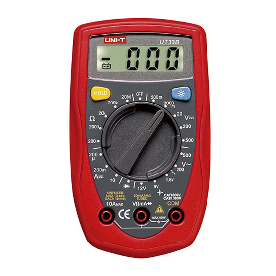
UT33 B/C/D OPERATING MANUAL
UNI-T
UT33B/C/D
Operating Manual
Palm Size Digital
Multimeter
SafetyInformation
This Meter
compli e swith the standards IEC61010: in poll
u
tion
deg
ree2,
overvol t age
category(CAT
1600V,
CAT II
300V)and
double
insulation,
CAT.
I: Signal level,
special
equipment
or part
s
of
equipment,
telecommunication,electronic,
etc.,
with smaller
transi
e nt
overvol t ages than overvoltages CAT.
II.
CAT. II: Local
level,
appliance,
PORTABLE
EOU
EHT ele.
,
with smallertransient overvol t ages
than CAT.
IU
Use the Mete
r
only
as
specified in this
opera'
otherwise the
protection provided by the
e
S
f
impaired.
In this manual,
a Waming identifies
con
ditions
and
aclioos
pose
hazards
to
the use
r,
or
may damage the
er
or
equipment
under test. A Note
identifies
theinfonnation
Ihal
user
should
payattentionon.
Intemational electrical
symbols used on
the Me
ter
andin this
Operating
Ma nualareexplainedonpege
10.
Rules
For
SafeOperation
.<!>
Waming
Toavoid possibleelec
tric
shock
or persona
•
to
avoid possible damage to the
Met
e r
or
to the
equipme
undertest, adhere to
thefollowing
rules:
• Befor
e
using the Met
e r
inspectthe
case.
Donot
usethe
Meter if
it
is damaged or the case (or
part of
the case) is
removed.
Lookfor cracksor
missing plastic.Payattention
to the insulation around the connectors.
• Inspect the test leads for damaged insulation
or
exposed metal. Check the test leads for
continuity.
Replace
damaged test leads with
identical
model
number
or
electrical
specifications
beforeusing
the
Meter.
• Donot apply morethan the rated voltage
.
as
marlted on
the Meter
,
between the
terminals or between any
terminal
andgrounding
,
• Therotary
switch should
be
placed in the
right position
and no any
changeover
of
range shall
be made during
measurement is conducted
to
prevent
damage
of
the
Meter.
•
When the Meterworlting
at
an
effecti v e voltage
over 60V
in DCor
42V
rms in
AC,
specia
l
care should
be
taken for
thereis dangerof
electric
shock.
• Usethe propertermi n
als, function,
and rangefor your
measurements.
• Do not use or store the Meter in an
environment of
high
temperature,
humidity,
explosive,
inflammable and
strong magnet
i c
field.The performance of the Metermay
deteri
o
rateafterdampened.
• When
using
thetest leads, keepyour fingers behi
n d
the
fingerguards
.
•
Disconnect
circuit
poweranddischa
rge
all
high-voltage
capacitors before
testing resistance,
continuity,
diodes
andcurrent.
•
Before
measuring current, checkthe Meter
' s
fuses
and
tum off powerto the
circuit
beforeconnecting
the Me
ter
to
the
circuit.
• Replac
e the
battery as soon as the battery
indicator
appears.With
a
low battery
,
the Meter might
produce
false
readings that can lead to electric
shock
and
personal
injury.
• Remove test leads and temperature probe from
the
Meter and turn the Meter power off
before opening the
Metercase
,
• When servicing the
Meter,
use only the same
model
numberor identical electrical
specificationsreplacement
parts,
• The internal circuit of the Metershall not be
attered
at
will to avoiddamage of the
Meterandany aceld
e
• Soft cloth and
mild detergent should be used to de
the surfac
e of
the Meter when
servicing.
No abras
M! and
solventshould
be usedto
prevent the surfaceof the Mete
r
from
corrosion,
damage
andaccident.
•
The eter
is
suitablefor indoor use.
•
Tum
the Meteroff when it is
not in
use
and take
out the battery
whennot using for
a long
time.
•
Constantly
check the battery as it mayleakwhenit has been
using
for
some
time,
replacethe battery as soon as leaking
appears.
A
leaking
battery
will
damage
the
Meter
.
~
-
ACor
OC
~
LowBattery
ACCurrent
-+I-
Diode
ocCurrent
-
Fuse
•
Ear.h Ground
>'1)
Co
ntin uityTest
a
llotilIe
Insulated
l!>
Safety Ruless
cs
Con/orms
to
Standards of Eu
NV
an
Un
ion
The
eter
Structure(figure
1)
1)
2)
6
3)
DisDIav
Bad<IIchI Button
4}
5)
6)
7)
Figure
1
ss
once
enter
m
e.
•
Press
HOLD
agom
to
exit hold mode.
•
In
H<*l mod
e,l:Iis
displayde an
thepresent value
shown
.
•
Press
BLUE
buttononceto tumthedisplay
backlight
on.
• PressBLUE
button again to tumthe display backlight
off.
•
Display
backlight willNO
T
beautomatically
offunless
pressing
theBLUE button.
indicated for
information about the functional
button
I
BLUE
button
Measurement
Operation
A.
DCVoItage
asurem ent(seefigure
2)
Figure2
.<!>
Warning
To
avoi
d harms to you or damages to the Meter from electric
shock,
pleasedo not attempt to
measure
voltages higherthan 500V although
readings may
beobtained.
The DC Voltage rang
es are
: 200mV, 2000mV, 20V,200 V
and
soev
To
measml
OC
•
connecttheMe
ter asfollows:
1.
Insert the red
test
leadinto
theVQmAtermina l
and theblack testlead
into the
COM
.
2.
Set
the rotary
swtch
kl
an
appropriate
measurement
position in
V::=
range.
3. Connect
the Ieslleads across
the
obj
e ctbei
n g
measured.
The measured
:.ows
on
display.
be
obtained.
Val
I agl ' lIl!aSlJrement (see
figure
2)
..,oId
hanm
to you
or
damages to the Meter from electric
shock,
The
AC
valage
are:
200V
and
SOOV.
Tomeasure
AC~'
connect
the
eteras
foIows:
1.
lnsert
theredtestleadinto the VQmA termi n al and theblacktes
t
lead
intotheCOMterm inal.
2. Set therotary
swi t ch
to
an appropriate measurementpos
iti o
nin
V
range.
3.
Connectthetest
leads
across with theobjectbeing
measured
.
Themeasured value sho
wson
thedispla
y,
which is
effective value of
sine
wav
e (mea n
valueresponse).
Note
•
If the value of voltage
to
be measured is unknown
, use
the
max
imum
measurement
pos
ition (500V) and reduce the range
stepbystepuntil a sat
i sfactory
reading is
obtained.
•
TheLCD displays "1" indicating the existing
selected
range is
ove
rload,
it is required to select a higherran gein
order
to
obtai n
a
corre
ct
reading
.
•
In
each
range, the Meter has an input impedance of app
rox.
10MQ
.
Thisloading effe
ct
can cause measurement errors in high
impedan
cecircuits. If thecircuitimpedance is lessthan or equal to
1OkQ,
theerroris negligible (0.1
% orless).
•
When AC vollage measurement has been completed,
disconnect the connection between the
testing
leads and the
circ uitunder tesl.
C.
DCCurrentMeasurement (see figure
3)
Figure
3
.<!>
Warning
Neverattempt an
in-circuit
current measurement where the
voltage betweenterminals and ground is greaterthan 60V.
If the fuse burns out during
measurement,the
Me
ter
may be
damaged or the operator
himself
may be
hurt.
Use proper
terminals,function,and range
for the
measureme nt.W hen
the
testing
leadsare connectedto the current
terminals,
do not
para
llel themacross
anycircuit.
TheModel
UT33B:
thecurrent measurement has 3
measurement
positions
on
the
rotary swi
t ch:
200!,
A,
200mAand
l
OA.
The Model
UT33CIUT33D
: the current
measurement
has 4
measurementpositi
o ns on the rotary switch:
2000,uA, 20mA,
200 mAand10A
Tomeasure current,
dothefollowing:
1.
Turn off power to the circuit.
Discharge all high-voltage
capacitors.
2.
Insert thered
lestlead into
theVQmA
or
lOAterminal andthe
black
testleadintotheCO
Mterminal.
3.-set
the
rotaryswitchto an
appropriate
measurement positionin
A:=
range.
4.
Brea
curr
e
ntpath
to
betested.Connect
thered test lead to
the
more
p<lSlIjW
sid
e
of
the break andthe black testlead
to
the
more
negative SIde of
break.
5.
Tum
onpower to
the
cirtuil.
Themeasure d
value
shows
on
the
display.
Note
•
If the
value
of
current
1
0 be measured
is
unknown,
use the
maxi m u m measurement
position(10A)
•
andreducetherange stepbystep
unti l a
satisfactoryreading is
obtai n ed.
•
When current measurement has bee
n completed.disconnect
theconneclionbetween
thetesting
leads
• andthecircuit under
test.
D. Measuring Resistance (seefigure
4)
Figure
4
.<!>
Warning
To avoid damages to the Meteror to the devices under
test,
disconnect circuit
powe
r
and dischargeall the high-voltage
capaci t ors
before measuring resistance.
The Model
UT33B/UT33C:
The
resistance
measurement
positions
are:
200Q
, 2000Q,20kQ,
200kQ
and20MQ.
TheModelUT33D: Theresistance measurement
positionsare:
200Q
, 2000Q, 20kQ, 200kQ,20MQ and
200MQ
Tomeasure
resistance,
connect
theMeter
as
follows:
1.
Insert the red
test lead
intothe VQmA terminal and
theblack
testlead
intotheCOM
terminal.
2.
Settherotary switch to anapp
ropriate
measurementpositionin
Q
range.
3.
Connect thetestleads
across
wi
t
htheobje
ct beingmeasured.
The
measured
value shows
onthedisplay.
Note
•
The
test
leadscan
add 0.1Q
to
0.3Q of errorto resistance
eas rement. Toobtain
precisio n readings in
low-re sistance
measurement. that is the range of 200Q.short-circuit the
input
terminals
beforehand
andrecord
thereading
obtained
(called
this
readinaas
Xl. (Xl
Is
theadditional resistance from
thetestlead.
Advertisement


Need help?
Do you have a question about the UT33B and is the answer not in the manual?
Questions and answers